

Page 1
Thank you for purchasing TOA's Remote Controller. Please carefully follow the instructions in this
manual to ensure long, trouble-free use of your equipment.
REMOTE CONTROLLER
C-RM700
OPERATING INSTRUCTIONS
Page 2

2
TABLE OF CONTENTS
1. SAFETY PRECAUTIONS ............................................................................... 4
2. GENERAL DESCRIPTION ............................................................................. 6
3. FUNCTIONS ........................................................................................................ 6
4. CONNECTABLE EQUIPMENT
AND THEIR MAXIMUM NUMBERS
..................................................... 7
4.1. About Controllable Equipment by the C-RM700 ............................................... 7
4.2. About the Camera Control Terminal ................................................................. 7
5. NOMENCLATURE AND FUNCTIONS
Top .......................................................................................................................... 8
Rear ........................................................................................................................ 10
6. OPERATION
6.1. Operating the Camera ..................................................................................... 11
6.1.1. Selecting cameras for operation ........................................................... 12
6.1.2. Rotating the camera with the joystick ................................................... 13
6.1.3. Activating the wiper ............................................................................... 13
6.1.4. Controlling an auxiliary contact 1 .......................................................... 14
6.1.5. Controlling an auxiliary contact 2 .......................................................... 14
6.1.6. Activating the automatic functions ........................................................ 15
6.1.7. Activating the focus function ................................................................. 15
6.1.8. Changing the lens speed ...................................................................... 16
6.1.9. Activating the auto-focus function ......................................................... 16
6.1.10. Selecting the camera position ............................................................. 16
6.2. Monitor Display ............................................................................................... 17
6.2.1. Viewing full-screen displays .................................................................. 17
6.2.2. Viewing multi-screen displays
(only active when the Multi-Switcher is connected) ............................ 18
6.2.3. Viewing sequential displays .................................................................. 20
6.2.4. Displaying the camera number
(only active when the Multi-Switcher is connected) ............................ 21
6.2.5. Viewing the freeze screen
(only active when the Multi-Switcher is connected) ............................ 21
6.2.6. Using the function keys ......................................................................... 23
6.2.7. Using the abbreviated numbers ............................................................ 23
6.3. Alarm Hold and Reset ..................................................................................... 24
6.3.1. Holding the alarm .................................................................................. 24
6.3.2. Displaying alarm-activated camera images .......................................... 24
6.3.3. Resetting the alarm ............................................................................... 24
7. SETTINGS
7.1. Setting Items and Their Descriptions .............................................................. 25
7.2. Operating Keys and Display Screen ............................................................... 26
7.3. Basic Setting Operations ................................................................................. 27
7.3.1. When the password has not been set ................................................... 27
7.3.2. When the password has been set ......................................................... 28
7.4. Setting the Functions ...................................................................................... 29
7.4.1. Operation mode .................................................................................... 29
7.4.2. Switchers .............................................................................................. 29
7.4.3. Protocol ................................................................................................. 30
Page 3

3
7.4.4. Camera check ....................................................................................... 31
7.4.5. Manual speed (Protocol: Type B only) .................................................. 32
7.4.6. Auto-key (Settable to Type B by this unit) ............................................. 32
7.4.7. Time adjustment (Protocol: Type B only) .............................................. 33
7.4.8. Automatic reset ..................................................................................... 33
7.4.9. Home position ....................................................................................... 34
7.4.10. I/O speed ............................................................................................ 35
7.4.11. Buzzer ................................................................................................. 36
7.4.12. Initial screen ........................................................................................ 36
7.4.13. Channel designation ........................................................................... 37
7.4.14. Sensor alarm ....................................................................................... 38
7.4.15. Camera alarm ..................................................................................... 38
7.4.16. Camera alarm preset .......................................................................... 39
7.4.17. Alarm signal ........................................................................................ 40
7.4.18. Alarm time ........................................................................................... 40
7.4.19. Alarm function ..................................................................................... 41
7.4.20. Alarm hold ........................................................................................... 41
7.4.21. Function .............................................................................................. 42
7.4.22. Abbreviation ........................................................................................ 44
7.4.23. Tour sequence .................................................................................... 45
7.4.24. Camera menu ..................................................................................... 46
7.4.25. I/O selection ........................................................................................ 46
7.4.26. Password ............................................................................................ 47
7.5. Adjusting the Joystick Position ........................................................................ 47
8. CONNECTIONS
8.1. Connection to Combination Cameras ............................................................. 48
8.2. Connection to Multiple Combination Cameras ................................................ 48
8.3. Connection to the Alarm Unit .......................................................................... 49
8.4. Connection when Controlling the System from 2 Locations ............................ 49
8.5. Connection to the Multi-Switcher .................................................................... 50
8.6. Alarm Output/Control Input Terminal Connections ......................................... 51
8.6.1. Assembling D-sub connectors onto cables ........................................... 52
8.7. System Example ............................................................................................. 53
9. LIST OF FUNCTION SETTINGS
9.1. Auto-Key Settings ........................................................................................... 54
9.2. Function Key Settings ..................................................................................... 55
10. SPECIFICATIONS
Accessory ................................................................................................................ 56
Page 4
4
1. SAFETY PRECAUTIONS
• Before installation or use, be sure to carefully read all the instructions in this section for correct and safe
operation.
• Make sure to observe the instructions in this manual as the conventions of safety symbols and messages
regarded as very important precautions are included.
• We also recommend you keep this instruction manual handy for future reference.
Safety Symbol and Message Conventions
Safety symbols and messages described below are used in this manual to prevent bodily injury and property
damage which could result from mishandling. Before operating your product, read this manual first and
understand the safety symbols and messages so you are thoroughly aware of the potential safety hazards.
Indicates a potentially hazardous situation which, if mishandled, could
result in death or serious personal injury.
WARNING
Do not expose the unit to rain or an environment where it may be
splashed by water or other liquids, as doing so may result in fire or
electric shock.
WARNING
• This is a class A product. In a domestic environment this product may cause radio interference in which case
the user may be required to take adequate measures.
• Use the unit only with the voltage specified on the unit. Using a voltage higher than that which is specified
may result in fire or electric shock.
• Do not cut, kink, otherwise damage nor modify the power supply cord. In addition, avoid using the power
cord in close proximity to heaters, and never place heavy objects -- including the unit itself -- on the power
cord, as doing so may result in fire or electric shock.
• Avoid installing or mounting the unit in unstable locations, such as on a rickety table or a slanted surface.
Doing so may result in the unit falling down and causing personal injury and/or property damage.
• Should the following irregularity be found during use, immediately switch off the power, disconnect the power
supply plug from the AC outlet and contact your nearest TOA dealer. Make no further attempt to operate the
unit in this condition as this may cause fire or electric shock.
· If you detect smoke or a strange smell coming from the unit.
· If water or any metallic object gets into the unit.
· If the unit falls, or the unit case breaks.
· If the power supply cord is damaged (exposure of the core, disconnection, etc.)
· If it is malfunctioning (no tone sounds.)
· If it is malfunctioning (no image appears.)
• To prevent a fire or electric shock, never open nor remove the unit case as there are high voltage
components inside the unit. Refer all servicing to qualified service personnel.
• Do not place cups, bowls, or other containers of liquid or metallic objects on top of the unit. If they
accidentally spill into the unit, this may cause a fire or electric shock.
• Do not touch a power supply plug or a coaxial cable during thunder and lightning, as this may result in
electric shock.
Page 5

5
Indicates a potentially hazardous situation which, if mishandled, could
result in moderate or minor personal injury, and/or property damage.
CAUTION
• Never plug in nor remove the power supply plug with wet hands, as doing so may cause electric shock.
• When unplugging the power supply cord, be sure to grasp the power supply plug; never pull on the cord
itself. Operating the unit with a damaged power supply cord may cause a fire or electric shock.
• When moving the unit, be sure to remove its power supply cord from the wall outlet. Moving the unit with the
power cord connected to the outlet may cause damage to the power cord, resulting in fire or electric shock.
When removing the power cord, be sure to hold its plug to pull.
• Avoid installing the unit in humid or dusty locations, in locations exposed to the direct sunlight, near the
heaters, or in locations generating sooty smoke or steam as doing otherwise may result in fire or electric
shock.
• Do not place heavy objects on the unit as this may cause it to fall or break which may result in personal
injury and/or property damage. In addition, the object itself may fall off and cause injury and/or damage.
• Use the specified AC adapter for the unit. Note that the use of other adapter may cause a fire.
• If dust accumulates on the power supply plug or in the wall AC outlet, a fire may result. Clean it periodically.
In addition, insert the plug in the wall outlet securely.
• Switch off the power for safety purposes when cleaning or leaving the unit unused for 10 days or more.
Doing otherwise may cause a fire or electric shock.
Note
This equipment has been tested and found to comply with the limits for a Class A digital device,
pursuant to Part 15 of the FCC Rules. These limits are designed to provide reasonable protection
against harmful interference when the equipment is operated in a commercial environment. This
equipment generates, uses, and can radiate radio frequency energy and, if not installed and used in
accordance with the instruction manual, may cause harmful interference to radio communications.
Operation of this equipment in a residential area is likely to cause harmful interference in which case the
user will be required to correct the interference at his own expense.
Modifications
Any modifications made to this device that are not approved by TOA Corporation may void the authority
granted to the user by the FCC to operate this equipment.
CU version complies with Part 15 of the FCC Rules.
Page 6

6
2. GENERAL DESCRIPTION
The TOA C-RM700 Remote Controller is used to remotely control TOA Combination cameras over
communication lines (RS-485). It can remotely control up to 16 camera image switching and cameras in
combination with TOA Multi-Switcher. Also, it is equipped with a 3-axis joystick that permits main operation to
be performed with one hand.
3. FUNCTIONS
• Display Selection Function
The following screen formats can be selected for display of camera images connected to the Multi-Switcher:
full screen, 4-segment, sequential 4-segment, 9-segment, 10-segment or 16-segment split-screen and
sequential full-screen.
• Manual Operation Function
Controls the Combination camera's zoom, focus, pan and tilt functions.
• Preset Position Playback function
Controls the Combination camera's orientation, and displays the camera image on the monitor in the
selected orientation.
• Function Key Programming
Camera numbers or camera number/position combination numbers can be programmed into the function
keys (F1
-
F8).
Pressing the function key (F1 -F8) displays the camera image on the full screen. If position numbers have
been set, images of the selected camera orientation can be displayed.
• Abbreviated Number Function (Quick Display Function)
Permits camera numbers or camera number/position combination numbers to be programmed for numbers
1
-
520 depending on settings.
Entering the programmed number with the numeric key pad followed by the SET key displays the camera
images through the camera corresponding the camera number on the full screen, and the image of selected
camera orientation if the position number has been set.
• Alarm Function
Controls the display screen in synchronization with alarm signals input to the surveillance camera system to
which the unit is connected.
When an alarm signal is detected, the image of the corresponding camera takes display precedence. The CRM700 also features an Alarm Hold function that temporarily disables channel (camera number) switching in
response to an alarm signal.
This Alarm Hold function prevents the currently displayed screen from being forcibly switched to an alarmcalled screen by an alarm input during alarm hold. (when the Multi-Switcher is connected)
• Camera Protocol
It is equipped with TOA Type A,and TOA Type B which can control TOA Combination Cameras.
Page 7

7
4. CONNECTABLE EQUIPMENT AND THEIR MAXIMUM NUMBERS
4.1. About Controllable Equipment by the C-RM700
Shown below are equipment that can be controlled by the C-RM700.
Camera
[Communication method: Type A]: C-CC504, and C-CC554
[Communication method: Type A/B]: C-CC514, C-CC564, C-CC574, C-CC704, C-CC714, C-CC764, and
C-CC774
Up to 16 each of camera can be connected to the camera control terminals and controlled.)
Switcher: C-MS91D, C-MS91S, C-MS161D, and C-MS161S
Only one switcher can be connected for remote camera control.
4.2. About the Camera Control Terminal
The Camera control terminal is used to connect the Combination Camera or the C-IF500 Interface Unit. Up to
16 cameras can be connected to this terminal.
After connection completion of all cameras, turn on the power of cameras and the C-RM700, and initialize the
cameras. Then be sure to perform camera check after the camera's initialization operation has been
completed. (Refer to p. 31, "Camera Check.")
About the Descriptions in This Manual
• The explanations in this manual assume that the C-RM700 Remote Controller (this unit) is connected to
a C-MS161D/S or C-MS91D/S Multi-Switcher.
• Camera number: Refers to the camera input terminal number connected to the switcher.
• Position number: Combination camera orientation can be programmed for No. 1
-
255.
Page 8
8
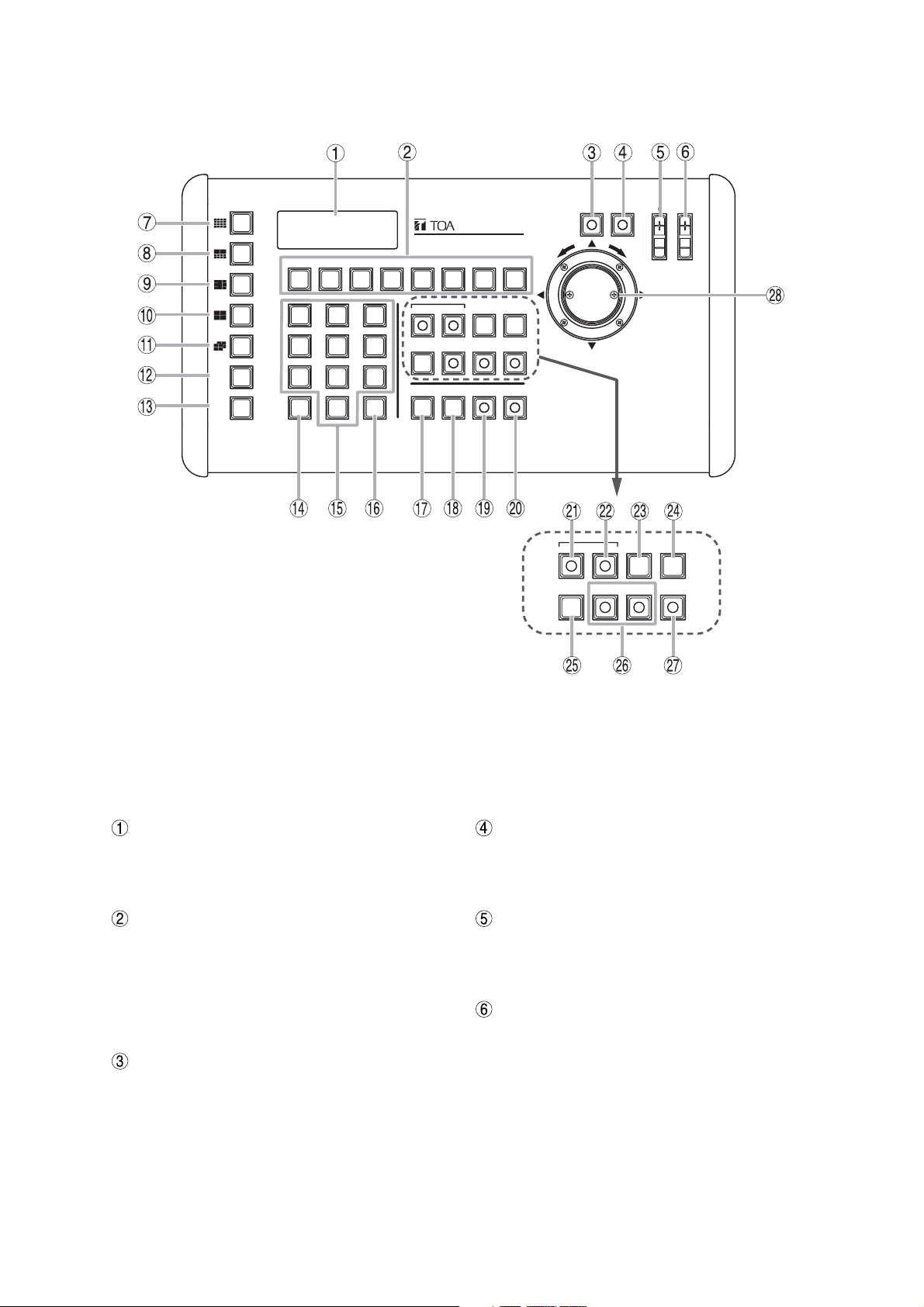
LCD screen
Displays character information for the setting
menu, numeric keypad input status, current
operation, etc.
Function keys [F1
-
F8]
A single depression of one of these keys displays
the full-screen image of the key's corresponding
preset camera number and position number.
Each key can also be set to activate automatic
operations (panning, tracing, preset sequence,
and tour) of the selected Combination camera.
Lens speed key
*2
Adjusts the speed of lens operation when the
Zoom or Focus key is pressed.
The focus moves slowly while the key lights.
Used to fine adjust the focus.
Auto-focus key
*2
Enables the Combination camera's Auto-focus
function. This key can only be used when the
Control key is lighting.
Focus key
*2
Sets the Combination camera's zoom lens for
"FAR" or "NEAR" operation. The Focus key can
only be used when the Control key is lighting.
Iris key
Adjust the camera's iris level.
Note
This key cannot be used for the camera with a
type A communication method.
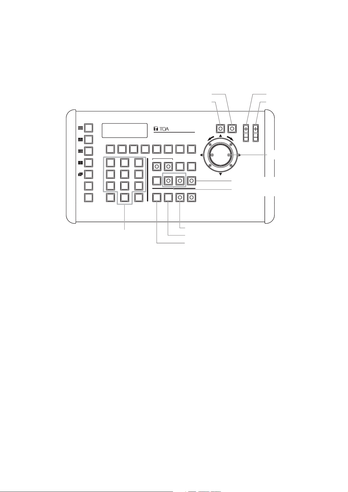
5. NOMENCLATURE AND FUNCTIONS
[Top]
Notes
Depending on the system configuration, the operation of some keys may be disabled. The corresponding keys
are marked with the following indications.
*1
Functions only when the multi-switcher is connected to this unit.
*2
Functions only when the Combination camera is connected to this unit.
REMOTE CONTROLLER C-RM700
WIDE TELE
F8F7F6F5F4F3F2F1
LENS SPEED
FOCUS
AF
IRIS
GROUP
SELECT
SEQUENCE
ALARM
21
3
654
987
C
SET
0
HOLDRESET
WIPER AUX1 AUX2 AUTO
POSITION
CAMERA
CONTROL
MENUCH
FREEZE
ALARM
HOLDRESET
WIPER AUX1 AUX2 AUTO
MENUCH
Page 9

9
16-segment split-screen key
*1
Displays camera images in the 16-segment split
screen format on the monitor.
10-segment split-screen key
*1
Displays camera images in the 10-segment split
screen format on the monitor. Each depression
of this key during the 10-segment split screen
display switches the screen between Group 1
image display and Group 2 image display.
9-segment split-screen key
*1
Displays camera images in the 9-segment split
screen format on the monitor. Each depression of
this key during the 9-segment split screen display
switches the screen between Group 1 image
display and Group 2 image display.
4-segment split-screen key
*1
Displays camera images in the 4-segment split
screen format. Each depression of this key during
the 4-segment split screen display cycles through
screens showing images of Groups 1 to 4.
Sequential 4-segment split-screen key
*1
Sequentially cycles through all connected
camera outputs of up to 4 groups of cameras at
a preset time interval, and displays camera
images in the 4-segment split screen format on
the monitor. (Sequencing interval is set at the
Switcher.)
Group selector key
*1
Switches on-screen camera groups during 4-, 9or 10-segment split-screen display on the
monitor.
Sequence key
*1
Sequences all connected camera outputs to the
full screen at the specified time interval.
(Sequencing interval is set at the Switcher.)
Clear key [C]
Used to correct entry errors through numeric
keypad. Also, turns off the buzzer when sounded
by an activated alarm.
Numeric keypad [0
-
9]
Used to enter the camera number, position
number, abbreviated number, etc.
SET key
Used in conjunction with the numeric keypad to
program the camera number or position number.
Also, if pressed after entering the set abbreviated
number with the numeric key, the full-screen
camera image corresponding to that number can
be displayed on the monitor.
Camera key
Displays the full-screen camera image
corresponding to the specified camera number.
This key does not function even if pressed
without entering the camera number.
Position key
Orients the Combination camera toward the set
direction. The Position key can only be used
when the Control key is lighting. Pressing the
Position key without designating the position
number orients the camera toward the direction
programmed under Position No. 1 (Home
position).
Control key
Used to designate the camera to be manually
controlled during a multi-screen display. This key
cannot be used during a full-screen or sequential
display. Also, nothing is operated even if this key
is pressed without designating the channel
number. The key lights when the camera is
controllable.
Freeze screen key
*1
Freezes camera images. However, sequential
displays cannot be made still. The key flashes
when there is a freeze image on the screen.
Alarm reset key
Resets the system's Alarm mode. The key
flashes during Alarm operation.
Alarm hold key
Places activated Alarm inputs on hold. The key
flashes during Alarm Hold.
CH call key
*1
Displays the camera number on the monitor for a
preset period of time.
This key is convenient for finding the camera
number when no indication or only the camera
name is displayed.
Menu key
When performing each setting, hold down the key
for 3 seconds or more to display the menu on the
LCD screen. Pressing the key again will close the
setting screen and the display will disappear.
Wiper key
*2
Remotely controls the outdoor-use Combination
camera's wiper. This key can only be used while
the Control key is lighting.
Auxiliary 1 and Auxiliary 2 keys
*2
Control (close or open) the Combination
camera's Auxiliary Contact Outputs.
The key lights when auxiliary contact is closed,
and goes out when open. This key can only be
used when the Control key is lighting.
Page 10
10
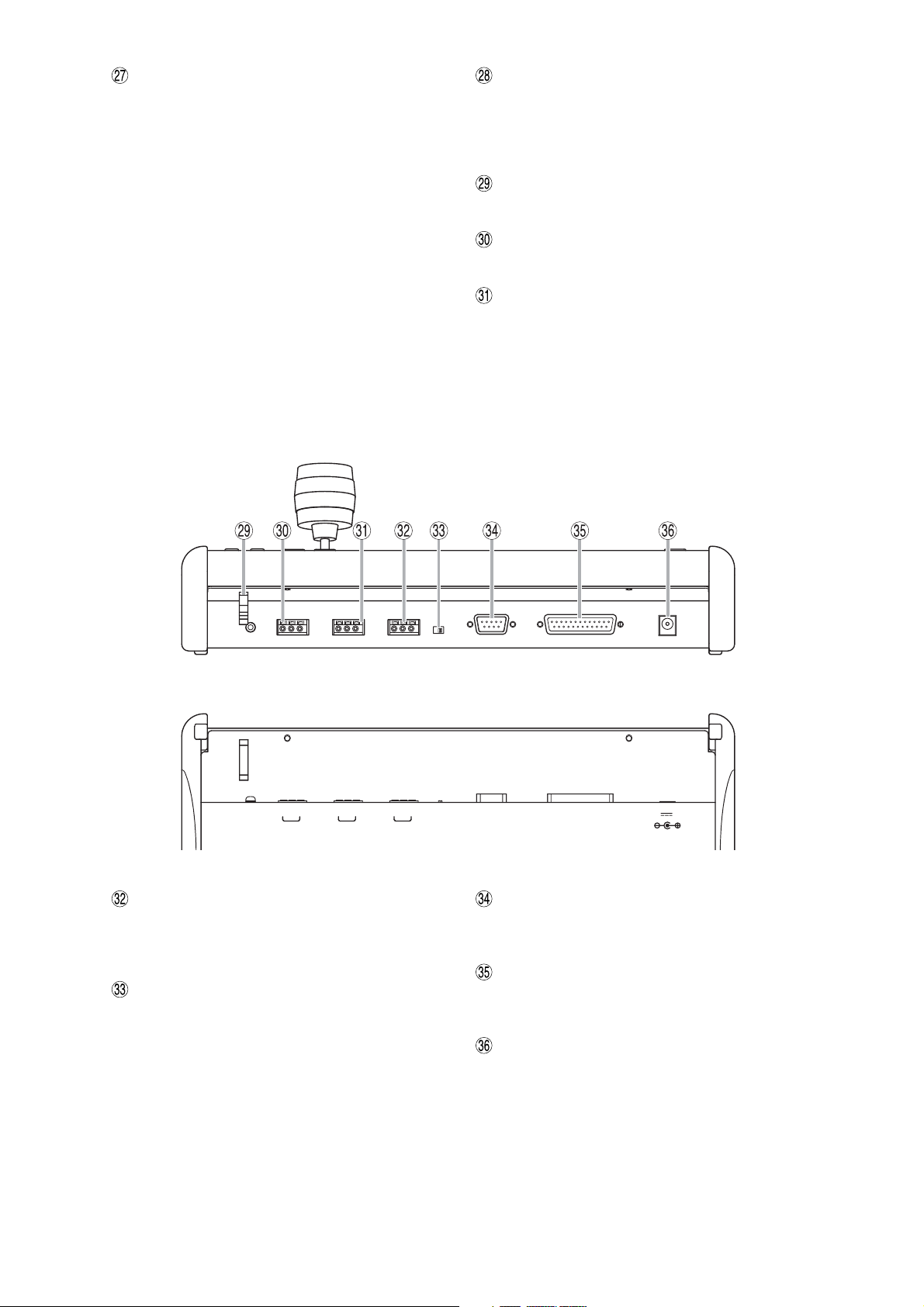
[Rear]
[Bottom surface] Note: Function indications (Silk printed) on the bottom surface
Switcher control terminals (RS-485)
Connect to the Multi-Switcher's dedicated remote
control terminal, and control the Switcher's
screen display.
Slave remote controller terminal termination
switch
Set to ON during normal use.
Alarm input terminal (RS-232C)
Connects to an alarm input unit to receive alarm
information.
Alarm output/Control input terminal
Closing the contact corresponding to the alarm
activated channel (camera number).
AC adapter power input terminal [12 V DC IN]
Insert the DC plug of the dedicated AC adapter
into this terminal.
Auto key
*2
Enables or disables the Combination camera's
automatic functions (Auto-Pan, Auto-Trace, and
Preset Sequence). The Auto key can only be
used when the Control key is lighting.
Auto-Pan: Automatically rotates the camera
horizontally.
Auto-Trace: Stores manual camera operations to
the Combination camera, and
automatically reproduces such
operations stored in memory.
Preset Sequence: Automatically reproduces the
camera images in the order of
preset position numbers.
Tour: Stores the preset and trace performed at
each camera in the order of desired
reproduction number, and automatically
reproduces such operation.
Joystick
*2
Used to move up, down, left, or right and zoom
in/out the camera with pan/tilt head connected to
the system. The joystick can only be used while
the Control key is lighting.
Cable holder
Used to bundle the cables.
Camera control terminals (RS-485)
Connect to the Combination camera.
Slave unit remote control terminals
Connect to another C-RM700 to be designated
as a slave unit for remote control from different
locations.
GND
-
+
CAMERA RIMOTE SWITCHER
GND-+
OFFON
GND-+
TERMINATION
(
RM CTRL
ALARM IN ALARM OUT
)
12V IN
Page 11
11
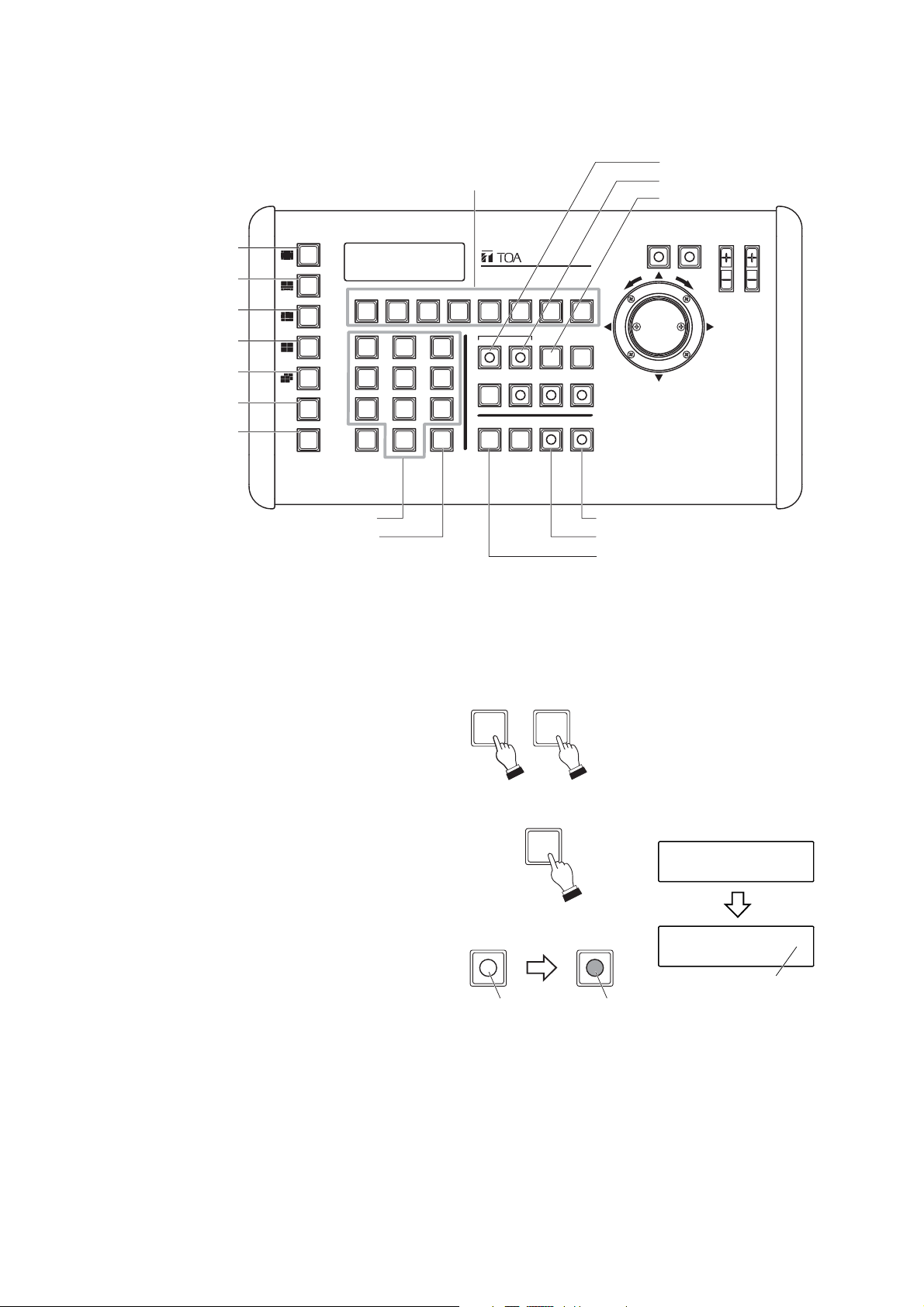
6. OPERATION
6.1. Operating the Camera
The following camera operations can be performed when the Control key is lighting.
[Operating keys]
GROUP
SELECT
SEQUENCE
21
C
SET
0
Numeric keypad
REMOTE CONTROLLER C-RM700
3
WIPER AUX1 AUX2 AUTO
654
987
CAMERA
Lens speed key
ALARM
HOLDRESET
POSITION
Auto-focus key
WIDE TELE
F8F7F6F5F4F3F2F1
MENUCH
CONTROL
FREEZE
Control key
Position key
Camera key
LENS SPEED
Focus key
Iris key
FOCUS
AF
IRIS
Joystick
Auto key
Auxiliary 1 and 2 keys
Page 12
12
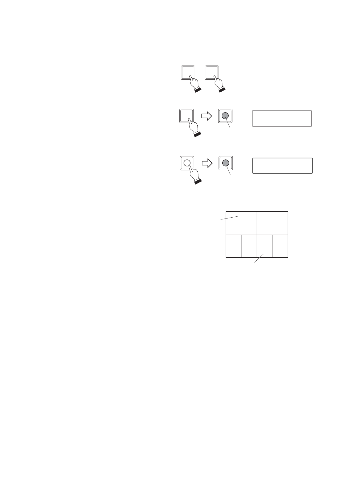
Note
Both XX and YY camera images can be freely set
using the Multi-switcher.
(Example)
6.1.1. Selecting cameras for operation
Cameras to be manually controlled can be selected during full-screen or multi-segment screen display.
1. Using the numerical keypad, press the desired
camera number.
2. Press either the Camera or Control key.
2-1. Operation in full-screen display format
Press the Camera key.
The Control key will light, permitting operation
of the designated camera.
2-2. Operation in multi-screen display format
Press the Control key during multiscreen
display.
The Control key will light, permitting operation
of the designated camera.
51
CAMERA
CONTROL
LCD screen
15 CAMERA 0 0 1
Lights
CONTROL
CONTROL
Lights
LCD screen
CONTROL
Monitor screen
(10-segment split-screen display)
Camera name
09 10 11 12
YYXX
13 14 15 16
This camera can be operated.
Page 13
13
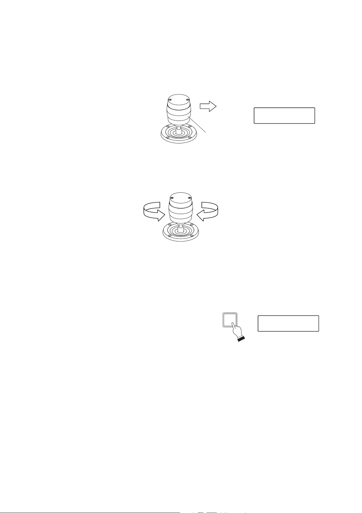
Rotate the joystick while the camera is selected.
Clockwise rotation: Telescope; Counterclockwise rotation: Wide angle.
6.1.3. Activating the wiper
When a Combination camera with built-in wiper is connected to the system, the wiper can be activated using
the Wiper key.
Press the Wiper key while the camera is selected.
The camera's built-in wiper is activated while the key is held
down.
6.1.2. Rotating the camera with the joystick
Any connected Combination camera can be rotated in the desired direction using a joystick.
With the camera selected, tilt the joystick in the direction in which the camera is to be rotated.
The camera will rotate in the direction the joystick was tilted.
(Example) When panning the camera to the right;
Wide angle Telescope
LCD screen
MANUAL
Joystick
WIPER
LCD screen
WI PER
Page 14
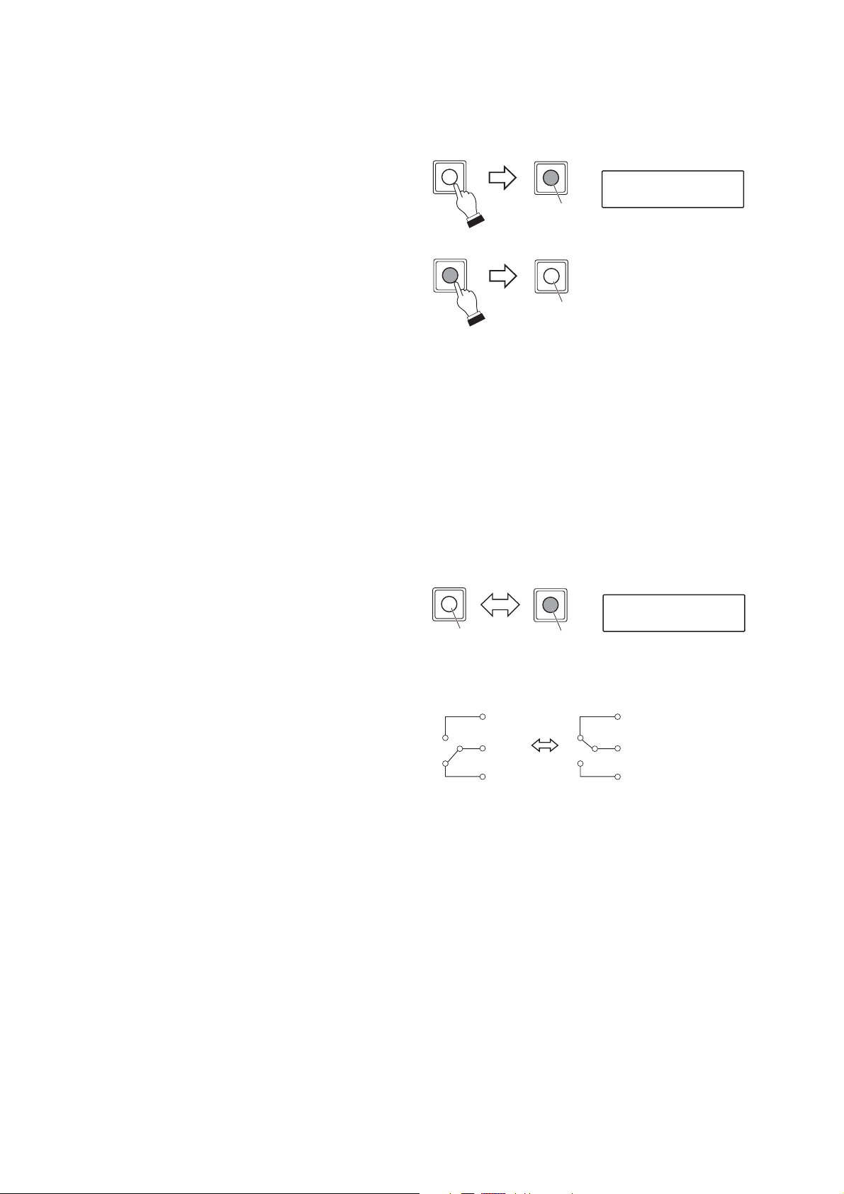
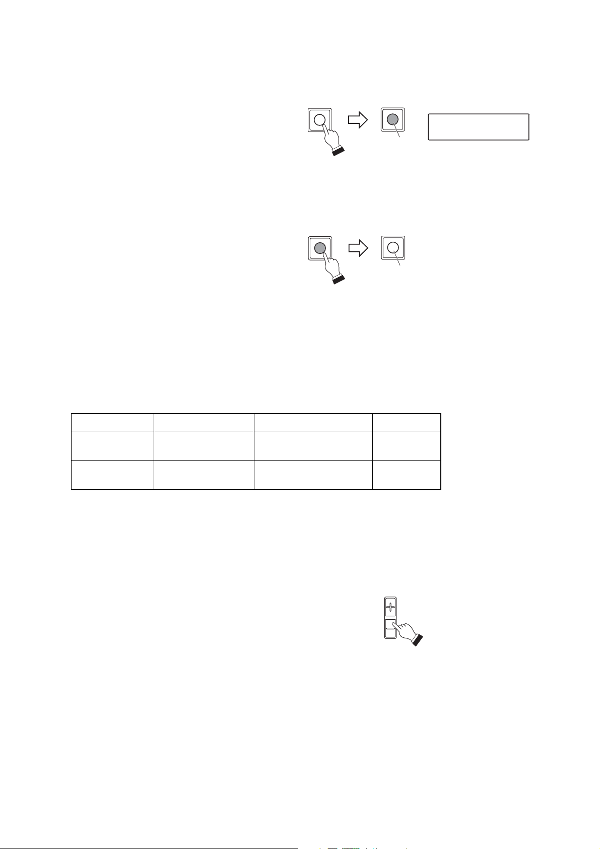
6.1.4. Controlling an auxiliary contact 1
The Combination camera's Auxiliary Contact Output 1 can be opened or closed.
1. Press the Auxiliary 1 key while the camera is
selected.
The Auxiliary 1 key will light and the auxiliary
contact output 1 is closed (ON).
2. Press the Auxiliary 1 key again.
The Auxiliary 1 key will extinguish and the
auxiliary contact output 1 is opened (OFF).
14
6.1.5. Controlling an auxiliary contact 2
Controls the Auxiliary Contact Output 2 of the C-CC504, C-CC514, C-CC554, C-CC564, and C-CC574.
[When the C-CC504, C-CC514, or C-CC554 is connected]
Auxiliary Contact Output 2 can be closed or opened in the same manner as for the Auxiliary Contact Output 1.
[When the C-CC564 or C-CC574 is connected]
1. Press the Auxiliary 2 key while the camera is
selected.
The Auxiliary 2 key will light and the Combination
camera's internal auxiliary contact output 2 is
activated.
2. Press the Auxiliary 2 key again.
The Auxiliary 2 key will extinguish and the
auxiliary contact output 2 switches.
AUX1
AUX1
LCD screen
AUX 1
Lights
AUX1
AUX1
Extinguishes
AUX2
Extinguishes
[
Extinguishes
NO
COM
NC
AUX2
Lights
]
LCD screen
[
Lights
AUX 2
]
NO
COM
NC
Page 15
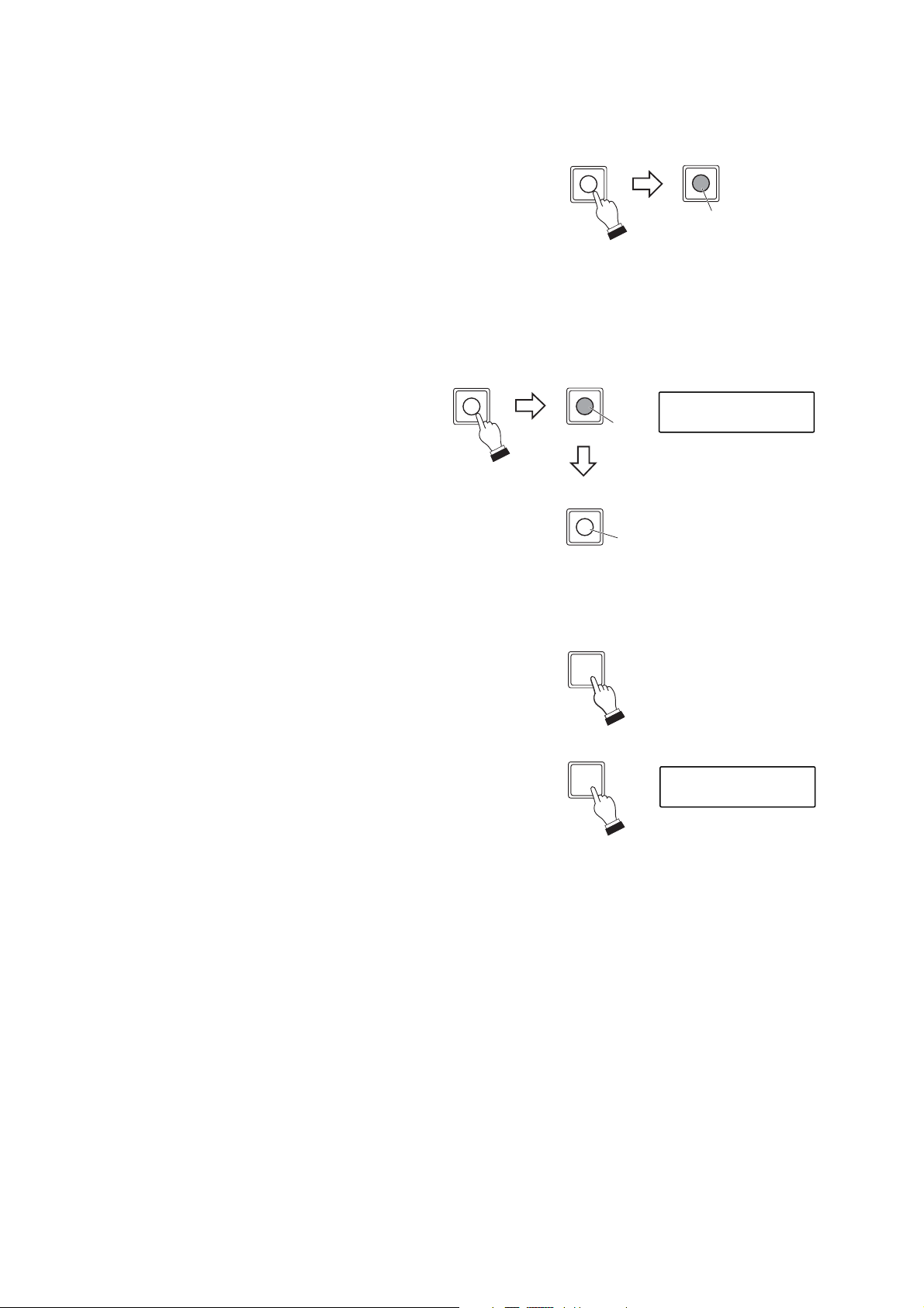
6.1.6. Activating the automatic functions
When a Combination camera is connected to the system, its automatic functions can be enabled using the
Auto key.
1. Press the Auto key while the camera is selected.
The Auto key will light and the camera's
automatic functions (Auto-pan, Auto trace,
Preset sequence, or Tour) will begin to operate.
Auto-pan:
Automatically rotates the camera horizontally.
Auto trace:
Automatic repetition of manual camera
operations that have been stored in memory.
Preset sequence:
Automatic sequential display of camera positions
in the order that their position numbers were
preset.
Tour:
Stores the preset and trace performed at each
camera in the order of desired reproduction
number, and automatically reproduces such
operation.
2. Press the Auto key again.
The Auto key extinguishes and automatic
operations are stopped.
Note
Setting destination to which automatic function to operate differs depending on the type of protocol of the
camera connected. Refer to the table below for details.
15
Protocol Setting destination Programming destination Referral page
TOA Type A Camera menu Camera p. 46
TOA Type B Auto-key Remote controller p. 32
6.1.7. Activating the focus function
When a Combination camera is connected, its image can be focused using the Focus key.
Press the Focus "+" or "-" key while the camera is selected.
Focusing continues as long as the key is pressed.
Pressing the "+" key focuses the lens on distant objects, and
pressing the "-" key focuses on near objects.
AUTO
AUTO
LCD screen
AUTO
Lights
AUTO
AUTO
Extinguishes
FOCUS
Page 16
16
6.1.9. Activating the auto-focus function
When a Combination camera is connected, the Auto-focus function can be activated with a press of the Autofocus key.
Press the Auto-focus key while the camera is
selected.
The key remains lit while the Auto-focus function
is in operation.
6.1.8. Changing the lens speed
The speed of lens movement when the Focus key is pressed can be adjusted.
Press the Lens speed key.
Lens speed decreases while the Lens speed key is lighting.
6.1.10. Selecting the camera position
1. Enter the camera position number with the numeric keypad.
2. Press the Position key.
The camera image corresponding to the selected position will
be displayed on the current monitor.
(Example)
LENS SPEED
LENS SPEED
Lights: Very slow
AF
AF
LCD screen
AUTO FOCUS
Lights
Auto-focus operation
AF
is completed.
Extinguishes
POSITION
5
LCD screen
5POSITION
Page 17
6.2.1. Viewing full-screen displays
1. Enter the camera number to be displayed on the
full screen using the numeric keypad.
2. Press the Camera key.
The designated camera image will be displayed
on the full screen.
Also, when the controllable camera is designated,
the Control key lights, permitting camera
operations with the joystick.
17
6.2. Monitor Display
[Operation keys]
(Example)
16-segment split
-screen key
10-segment split
-screen key
9-segment split
-screen key
4-segment split
-screen key
Sequential 4-segment
split-screen key
Group selector key
Sequential key
GROUP
SELECT
SEQUENCE
Alarm reset key
Function key
Alarm hold key
CH call key
FOCUS
AF
LENS SPEED
REMOTE CONTROLLER C-RM700
WIDE TELE
F8F7F6F5F4F3F2F1
ALARM
21
3
654
987
C
SET
0
HOLDRESET
WIPER AUX1 AUX2 AUTO
POSITION
CAMERA
CONTROL
MENUCH
FREEZE
IRIS
Numeric keypad
SET key
CONTROL
51
CAMERA
Freeze screen key
Control key
Camera key
CONTROL
LCD screen
15 CAMERA
0 15
Extinguishes
Lights
Camera number displayed
in full-screen format
Page 18

18
6.2.2. Viewing multi-screen displays (only active when the Multi-Switcher is connected)
[16-segment split-screen viewing]
Press the 16-segment split-screen key.
All connected camera images will be displayed on
the monitor.
[10-segment split-screen viewing]
1. Press the 10-segment split-screen key.
The images of camera numbers 1-8 (Group 1)
and 2 more images (settable with the Switcher)
will be displayed on the monitor.
2. Press the 10-segment split-screen key again, or
the Group selector key. The images of camera
numbers 9-16 (Group 2) and 2 more images
(settable with the Switcher) will be displayed on
the monitor.
LCD screen
Monitor screen
01 02 03 04
0605 07 08
09 10 11 12
1413 15 16
Camera number
LCD screen
16-SEGMEN
10-SEGMEN
OR
GROUP
SELECT
Camera name
Camera No.
Monitor screen (Group 1)
0401
01 02 03 04
05 06 07 08
Monitor screen (Group 2)
1309
09 10 11 12
13 14 15 16
Page 19

19
[9-segment split-screen viewing]
1. Press the 9-segment split-screen key.
The images of camera numbers 1-9 (Group 1)
will be displayed on the monitor.
2. Press the 9-segment split-screen key again, or
the Group selector key. The images of camera
numbers 10-16 (Group 2) will be displayed on
the monitor.
[4-segment split-screen viewing]
1. Press the 4-segment split-screen key.
The images of camera numbers 1-4 (Group 1)
will be displayed on the monitor.
2. Press the 4-segment split-screen key again, or
the Group selector key.
The images of camera numbers 5-8 (Group 2)
will be displayed on the monitor.
The displayed camera group is switched to
camera numbers 9
-
12 (Group 3), camera
numbers 13-16 (Group 4) and then back to
Group 1 each time the key is pressed.
LCD screen
9-SEGMENT
Monitor screen (Group 1)
01 02 03
OR
Camera number
GROUP
SELECT
04 05 06
07 08 09
Monitor screen (Group 2)
10 11 12
13 14 15
16
LCD screen
4-SEGMENT
Monitor screen (Group 1)
OR
Camera number
GROUP
SELECT
0201
0403
Monitor screen (Group 2)
0605
0807
Page 20

20
6.2.3. Viewing sequential displays
The outputs of all cameras connected to the switcher can be displayed on the monitor in sequential order at
viewing intervals preset at the switcher. The outputs of the cameras not connected cannot be displayed. For
details, refer to the instruction manual included with the switcher.
[Sequential full-screen viewing]
Press the Sequence key.
The images for Cameras 1-16 are displayed
in sequential order.
Note that if the Tour Sequence function has
been set, the camera images will be switched
in the order of the specified reproduction
number. (Refer to p. 45, "Tour sequence.")
Note: In this example, Camera No. 2 is not
displayed on the monitor because it is
not connected.
[Sequential 4-segment split-screen viewing]
1. Press the Sequential 4-segment splitscreen key.
4 groups of camera images are displayed
in 4-segment split screen automatically
being toggled in sequence.
2. Pressing the same key again stops the
display sequence at the currently displayed
screen.
SEQUENCE
LCD screen
SEQUENCE
Monitor screen
Camera No. 1
Camera No. 3
Camera name
Camera name
Camera No. 16
Camera name
Monitor screen
Camera name
Group1
Group4
LCD screen
4-SEGMENT
Group2
BBBBAAAA
DDDDCCCC
Group3
NNNNMMMM
PPPP OOOO
FFFFEEEE
HHHHGGGG
JJJJIIII
LLLLKKKK
Page 21

21
6.2.5. Viewing the freeze screen (only active when the Multi-Switcher is connected)
1. Enter the camera number to freeze using the
numeric keypad.
2. Press the Freeze screen key.
The "F" or "Freeze" indication will flash on the
corresponding camera image screen.
3. Repeat Steps 1 and 2 to freeze other camera
images.
(Example)
6.2.4. Displaying the camera number (only active when the Multi-Switcher is connected)
Press the CH call key while a camera image is displayed
on the monitor. All connected camera numbers will be
displayed.
Note
The camera number is displayed even when the camera is
not connected.
CH
LCD screen
CHANNEL CAL L
Monitor screen
(10-segment split-screen display)
01 02 03 04
05 06 07 08
Monitor screen
(10-segment split-screen display)
51
09 10 11 12
1612
1509
FREEZE
FREEZE
Flashes
Camera name
13 14 15 16
LCD screen
15 FREEZE
09
09 10 11 12
13 14 F 16
Freeze display indication
FREEZE
Page 22

22
[Simultaneously resetting all freeze displays]
Press the Freeze screen key.
[Resetting individual freeze displays]
1. Enter the camera number to reset the
freeze display using the numeric keypad.
2. Press the Freeze screen key.
(Example)
FREEZE
51
Monitor screen
(10-segment split-screen display)
FREEZE
09
FREEZE
Flashes Extinguishes
FREEZE
FREEZE
Flashes Extinguishes
09 10 F F
13 14 F 16
1509
09 10 F F
13 14 15 16
The freeze display will be reset.
LCD screen
Monitor screen
(10-segment split-screen display)
1509
09 10 11 12
13 14 15 16
Page 23

23
6.2.7. Using the abbreviated numbers
By merely entering the programmed abbreviated number with the numeric keypad followed by the SET key,
the camera image (camera number and position number) programmed can be displayed on the monitor.
(Refer to p. 44, "Abbreviation.")
1. Enter the abbreviated number using the
numeric keypad.
2. Press the SET key.
The programmed camera image (position) will
be displayed on the full screen. Also, when the
controllable camera is designated, the Control
key lights, permitting camera operations with
the joystick.
(Example)
6.2.6. Using the function keys
By simply pressing a Function key (F1-F8), the camera image (camera number and position number)
programmed into the key can be displayed on the monitor.(Refer to p. 42, "Function.")
Press a Function key (any one of F1-F8).
The corresponding camera image (camera number and position number) is displayed on the full screen of the
monitor.
Function key
F8F7F6F5F4F3F2F1
CONTROL
LCD screen
F 3 F UNCT I ON KEY
Lights
Displays the camera number
programmed into the Function key.
52
01
CONTROL
Extinguishes
SET
CONTROL
Lights
LCD screen
25 SET
001
Displays the camera number
programmed under the
abbreviated number.
Page 24

24
6.3. Alarm Hold and Reset
The Alarm can be held or reset when "1 Front" has been selected in the "Alarm Hold" setting, and is not
activated when "2. ALWAYS" has been selected. (Refer to p. 41, "Alarm hold.")
6.3.1. Holding the alarm
Press the Alarm hold key.
The Alarm hold key will flash.
6.3.3. Resetting the alarm
Press the Alarm reset key.
The Alarm reset key will extinguish, resetting the alarm state.
Note
The alarm cannot be reset when "2. LEVEL" has been selected in the Alarm Signal setting. The state of alarm
continues as long as an alarm signal input is received. (Refer to p. 40, "Alarm signal.")
6.3.2. Displaying alarm-activated camera images
Press the Alarm hold key.
The Alarm hold key will extinguish, displaying the alerted camera image on the monitor in full screen format.
[When an alarm signal is received during Alarm Hold]
The Alarm reset key flashes while the "AL HOLD" indication is displayed on the monitor.
ALARM
ALARM
HOLDRESET
HOLDRESET
Flashes
LCD screen
Monitor screen
ALARM
HOLDRESET
Flashes
ALARM
HOLDRESET
(4-segment split-screen display)
01
03
ALARM HOLD
AL HOLD
02
04
ALARM
HOLDRESET
ALARM
HOLDRESET
Monitor screen
ALARM
Extinguishes
ALARM
ALARM
HOLDRESET
HOLDRESET
Monitor screen
Extinguishes
0201
0403
Page 25

25
OPERATION MODE *
(p. 29)
Designates this unit as a master, or slave.
SWITCHER *
(p. 29)
Determines the type of switcher to be connected to this unit.
MANUAL SPEED
(p. 32)
Sets the combination camera's maximum rotation speed in manual
operation.
AUTO KEY
(p. 32)
Sets the automatic operation to ON or OFF when type B is
connected to this unit.
TIME ADJUSTMENT
(p. 33)
Sets whether or not to adjust the combination camera's clock.
ALARM HOLD
(p. 41)
Sets the monitor display to be switched when an alarm signal is
received.
PROTOCOL
(p. 30)
Sets the camera control protocol (RS-485 communication).
FUNCTION
(p. 42)
Displays the corresponding preset camera image (camera number and
position number) on the monitor by simply pressing a Function key.
ABBREVIATION
(p. 44)
Displays the corresponding preset camera image (camera number and
position number) on the monitor when the abbreviated number (entered
with the numeric keypad) is entered, followed by the SET key.
CAMERA MENU
(p. 46)
Calls up the camera's built-in menu screen, permitting various
Combination camera settings, such as present position.
I/O SELECTION
(p. 46)
Selects when outputting the operation commands from an RS232C port to a master remote controller.
AUTO RETURN
(p. 33)
Sets the function to automatically return the camera to a specified
(Home) position after operation completion.
HOME POS
(p. 34)
Sets the Combination camera's standby status when it is not
controlled at all.
BUZZER *
(p. 36)
Sets whether or not to sound a buzzer when an alarm is engaged.
CAMERA ALARM
(p. 38)
Sets to "ON" when using the Combination camera's alarm contact input.
PRESET CAM ALARM
(p. 39)
Sets the position number in which the Combination camera will
automatically face when an alarm contact close information is
received from the camera.(Only valid when "1. ON" has been
selected in the "Camera alarm" setting.)
I/O SPEED *
(p. 35)
Sets the transfer rate of each control terminal.
INITIAL SCREEN
(p. 36)
Sets the screen to be displayed on the monitor immediately after
the power is switched ON.
INITIAL CHANNEL
(p. 37)
Sets the channel (camera number) to be displayed first when the
power is switched ON.
SENSOR ALARM
(p. 38)
Set to "ON" when using the Sensor Alarm function.
ALARM SIGNAL
(p. 40)
Sets the type of alarm continued action.
PASSWORD
(p. 47)
Sets the password required to open the menu.
ALARM TIME
(p. 40)
Sets the time interval from alarm signal reception to reset.
ALARM FUNCTION
(p. 41)
Sets the monitor display method when an alarm signal is
received.(Only valid when "1. EDGE" has been selected in the
"Alarm signal" setting.)
TOUR SEQ
(p. 45)
Sequentially displays two or more camera outputs on the full screen
in order of reproduction (1
-
128) at preset time interval (seconds).
Note: Only the setting items marked with "*" can be performed when "2. SLAVE" has been selected in the
"Operation mode" setting. In this event, other items are not displayed on the menu screen.
CAMERA CHECK
(p. 31)
Checks the Combination camera connected to the camera control
terminal for 30 seconds.
7. SETTINGS
7.1. Setting Items and Their Descriptions
Page 26

26
[LCD screen display]
7.2. Operating Keys and Display Screen
[Keys to be used in setting operations]
LCD screen
Displays the setting items and their contents.
REMOTE CONTROLLER C-RM700
WIDE TELE
F8F7F6F5F4F3F2F1
Alarm reset key
Used for password setting.
FOCUS
LENS SPEED
AF
IRIS
GROUP
SELECT
SEQUENCE
Clear key
Returns the mode to the
setting item selection
without confirming the
setting contents.
ALARM
3
21
654
987
0
C
SET
HOLDRESET
WIPER AUX1 AUX2 AUTO
CONTROL
POSITION
CAMERA
FREEZE
SET key
Confirms the setting items
and contents.
Numeric keypad
Used for entering numbers.
Setting item
OPERAT I ON MODE
1.MASTER
MENUCH
Joystick
Selects setting items
when tilted up and down,
and setting contents
when tilted left and right.
Menu key
Holding down this key calls up the menu
display on the LCD screen. The menu display
returns to the normal screen if the key is pressed
again during setting.
Setting content
Page 27

27
7.3. Basic Setting Operations
This section shows basic operating procedures for each setting item.
7.3.1. When the password has not been set
1. Press the Menu key for 3 seconds or more.
The menu screen is displayed.
[Some operation examples]
2. Tilt the joystick up or down to select the setting item.
3. Press the SET key to confirm the setting item.
The current setting contents (if not set, the factorypredetermined setting contents) are displayed at the
lower part of the LCD screen.
In this event, one character "1" of the setting contents
flashes. (The flashing character differs depending on
the content.)
4. Tilt the joystick left or right to select the desired setting
content.
Note
Pressing the Clear key before Step 4 is completed will
return the display to the screen last shown (in Step 2)
before the SET key was pressed without storing the
setting contents.
5. Press the SET key to confirm the setting contents.
The display returns to the screen (in Step 2) to select
the setting item.
6. Repeat Steps 2-5 to continue to set other items.
Press the Menu key again when returning to the normal
screen after setting completion.
Note
All keys are disabled for a maximum period of 30 seconds when returning to the normal screen from the menu
screen without performing camera check if the Combination camera is not connected.
SET
OPERAT I ON MODE
(
Example
)
AUTO RETURN
AUTO RET URN
1.ON
AUTO RETURN
1.ON 10SEC
SET
AUTO RETURN
Page 28

28
7.3.2. When the password has been set
Note, however, that the password setting differs from those explained here. Refer to p. 47.
1. Press the Menu key for 3 seconds or more.
The password entry screen is displayed.
2. Enter the password (4 digits) using the numeric keypad.
3. Press the SET key.
If the entered password is correct, the menu screen is
displayed.
[Some operation examples]
4. Tilt the joystick up or down to select the setting item.
5. Press the SET key to confirm the setting item.
The current setting contents (if not set, the factorypredetermined setting contents) are displayed at the
lower part of the LCD screen.
In this event, one character "1" of the setting contents
flashes. (The flashing character differs depending on
the content.)
6. Tilt the joystick left or right to select the desired setting
content.
Note
Pressing the Clear key before Step 6 is completed will
return the display to the screen last shown (in Step 4)
before the SET key was pressed without storing the
setting contents.
7. Press the SET key to confirm the setting contents.
The display returns to the screen (in Step 4) to select
the setting item.
8. Repeat Steps 4-7 to continue to set other items.
Press the Menu key again when returning to the normal
screen after setting completion.
MENU
LCD screen
PASSWORD
(
Example
)
1 234
Press for 3 seconds
or more.
SET
SET
PASSWORD
1234
OPERAT I ON MODE
(
Example
)
AUTO RETURN
AUTO RET URN
1.ON
AUTO RETURN
1.ON 10SEC
SET
AUTO RETURN
Page 29

29
7.4. Setting the Functions
Perform the following settings referring to the Basic Setting Operations on p. 27.
After connection completion of all cameras, turn on the power of cameras and the C-RM700, and initialize the
cameras. Then be sure to perform camera check after the camera's initialization operation has been
completed. (Refer to p. 31, "Camera check.")
7.4.1. Operation mode
Sets this unit's operation mode.
1. Press the Menu key for 3 seconds or more to display the menu screen.
2. Tilt the joystick up or down to select "OPERATION MODE," and confirm it with the SET key.
The setting contents will appear on Line 2.
3. Tilt the joystick left or right to select one of the following setting contents and confirm it with the SET key.
[Setting contents]
1. MASTER
Be sure to select Master when only a single C-RM700 unit is used. When 2 units are
connected, set either unit as the Master and the other as "SLAVE."
2. SLAVE
When 2 units are connected, set either unit as "SLAVE," and the other as "MASTER."
Note: Operation mode is set to "1. MASTER" by the factory.
7.4.2. Switchers
Sets the type of switcher to be connected to this unit.
1. Press the Menu key for 3 seconds or more to display the menu screen.
2. Tilt the joystick up or down to select "SWITCHER," and confirm it with the SET key. The setting contents
will appear on Line 2.
3. Tilt the joystick left or right to select one of the following setting contents and confirm it with the SET key.
[Setting contents]
1. 16 INPUT
Select when the 16 channels Multi-Switcher is connected to the switcher control
terminal (RS-485) or a switcher is not connected to the terminal.
2. 9 INPUT A
Select when the 9 channels Multi-Switcher is connected to the switcher control
terminal (RS-485) and Camera 9's 4-segment split-screen display is set for "OFF" in
the Multi-Switcher settings.
3. 9 INPUT B
Select when the 9 channels Multi-Switcher is connected to the switcher control
terminal (RS-485) and Camera 9's 4-segment split-screen display is set for "ON" in
the Multi-Switcher settings.
Note: The switcher type is set to "1. 16 INPUT" by the factory.
OPERAT I ON MODE
1.MASTER
SW ITCHER
1 . 16 INPUT
Page 30

30
7.4.3. Protocol
Selects the type of camera control protocol (RS-485 communication).
1. Press the Menu key for 3 seconds or more to display the menu screen.
2. Tilt the joystick up or down to select "PROTOCOL," and confirm it with the SET key. The setting contents
will appear on Line 2.
3. Tilt the joystick left or right to select one of the following setting contents and confirm it with the SET key.
[Setting contents]
1. TYPE A
Select when connecting the type A communication controlled camera.
2. TYPE B
Select when connecting the type B communication controlled camera.
3. TYPE B ONE WAY
Select when controlling the Combination camera without receiving the response
from the camera. (Example: when controlling the Netcansee camera via a
network.)
Note: This will not ensure that combination cameras other than Netcansee
devices can be remotely controlled via communication network.
Note: The protocol type is set to "2. TYPE B" by the factory.
Notes
• For the controllable cameras, refer to p. 7, " About Controllable Equipment by the C-RM700."
• When "TYPE B ONE WAY" is selected;
C-CC514, C-CC564, C-CC574, C-CC714, C-CC764, and C-CC774:
Set the DIP SW2 No. 7 to the ON position. (Although the description of the DIP SW2 No. 7 is "Unused" in
the installation manual supplied with each camera, this setting is required when using the TYPE B ONE
WAY protocol.)
C-CC704:
Set the DIP SW No. 8 to the ON position. (Although the description of the DIP SW No. 8 is "Unused" in the
installation manual supplied with the C-CC704, this setting is required when using the TYPE B ONE WAY
protocol.)
In this “TYPE B ONE WAY” protocol, Auto-focus, Auxiliary 1, and Auxiliary 2 keys do not light. When a
camera to operate is selected during full-screen or multi-segment screen display, the control key always
lights regardless of the camera selected.
To stop each individual automatic operation, press the Auto-key while holding down the function key
assigned as a shift key.
To set each individual auxiliary contact to OFF, press each individual auxiliary key while holding down the
function key assigned as a shift key.
For the shift key setting, refer to p. 42, "Function."
PROTOCOL
1.TYPE B
Page 31

31
7.4.4. Camera check
Checks Combination Cameras connected to the Camera Control terminal for 30 seconds.
Notes
• Be sure to perform this camera check except when the "TYPE B ONE WAY" has been selected in Protocol
setting.
• Once the Camera Check has been completed, only the cameras recognized when the check was performed
can be controlled. Therefore, be sure to perform the camera check again whenever unrecognized cameras
are found or new cameras are added. Also, in case that unrecognized cameras are still found after
performing camera checks several times, check to be sure that there is no fault with protocol of the camera
side, communication speed settings, wirings, and protocol and I/O speed settings of this unit.
1. Press the Menu key for 3 seconds or more to display the menu screen.
2. Tilt the joystick up or down to select "CAMERA CHECK," and press the SET key.
3. Tilt the joystick left or right to select one of the following setting contents and confirm it with the SET key.
[When "1. Start" is pressed]
The check takes approximately 30 seconds. All keys are disabled during the check.
The check interval is counted down from "30" (seconds) displayed to the right of Line 1.
The camera numbers of the connected Combination cameras are displayed in numerical order on Line 2.
[When "2. Clear" is pressed]
Setting returns to the factory preset.
4. Press the Clear key to return to the menu screen.
The indication "OK" is displayed after the 30-second check is completed.
After check completion, connected cameras can be confirmed by tilting the joystick to the left or right to scroll
the screen.
(Example)
CAMERA CHECK 2 0
1,2,3,4,5,11,12
CAMERA CHECK OK
1,2,3,4,5,11,12
CAMERA CHECK OK
1,2,3,4,5,11,12
CAMERA CHECK OK
13 , 14
Page 32

32
7.4.5. Manual speed (Protocol: Type B only)
Sets the Combination camera's maximum rotation speed in manual operation.
1. Press the Menu key for 3 seconds or more to display the menu screen.
2. Tilt the joystick up or down to select "MANUAL SPEED," and confirm it with the SET key.
The setting contents will appear on Line 2.
3. Tilt the joystick left or right to select one of the following setting contents and confirm it with the SET key.
[Setting contents]
7.4.6. Auto-key (Settable to Type B by this unit)
Sets one of the automatic operations (Auto-pan, Auto-trace, Preset sequence and Tour) for the Combination
camera to ON or OFF. This function can only be enabled when the Control key is lighting.
Note: For the type A camera, perform automatic operation settings at the Combination camera.
1. Press the Menu key for 3 seconds or more to display the menu screen.
2. Tilt the joystick up or down to select "AUTO KEY," and confirm it with the SET key.
The setting contents will appear on Line 2.
3. Tilt the joystick left or right to select one of the following setting contents and confirm it with the SET key.
[Setting contents]
Note: The Auto key is set to "1. Auto-Pan" by the factory.
Note: Functions that can be used differs depending on the type of Combination camera. For the functions,
refer to p. 54, "Auto-key settings."
Note: The manual speed is set to "5. 120º /SEC" by the factory.
1. AUTO PAN Calls up the automatic panning function.
2. AUTO TRACE1
-
9. AUTO TRACE8
Stores the manual camera operations into the Combination camera, and
recalls the function to automatically reproduce such operations.
10. PRESET SEQ Calls up the function to automatically reproduce the camera images in the
order of preset numbers set to the Combination camera.
11. TOUR1 -26. TOUR16 Calls up tours stored in each camera.
1. 24º/SEC
3.
60º/SEC
5.
120º/SEC
7.
240º/SEC
2.
40º/SEC
4.
90º/SEC
6.
160º/SEC
8.
360º/SEC
MANUAL SPEED
1.24°/SEC
AUTO KEY
1.AUTO PAN
Page 33

33
7.4.7. Time adjustment (Protocol: Type B only)
The Combination camera's built-in clock can be set when the alarm output/control terminal (Pin 23) is closed
with the Ground. The cameras of which built-in clock can be adjusted are C-CC514, C-CC564, C-CC574, CCC764, and C-CC774. (Refer to p. 51, "Alarm Output/Control Input Terminal Connections."
1. Press the Menu key for 3 seconds or more to display the menu screen.
2. Tilt the joystick up or down to select "TIME ADJUSTMENT," and confirm it with the SET key.
The setting contents will appear on Line 2.
3. Tilt the joystick left or right to select one of the following setting contents and confirm it with the SET key.
[Setting contents]
1. OFF Disables time adjustment.
2. 1:00 -24. 23:00 Sets the time to receive contact input for the clock synchronization. Sends a
corresponding command relative to that time to the cameras.
Confirming this setting displays the screen for setting the time interval before
Automatic Reset occurs following camera operation.
Tilt the joystick left or right to select the reset interval: "10 SEC," "15 SEC," "20 SEC,"
"30 SEC," "1 MIN," "2 MIN," "3 MIN," "4 MIN" and "5 MIN." The selected time is
confirmed with the SET key.
Note: "SEC" of the reset interval stands for seconds, and "MIN" for minutes.
Disables the Automatic Reset function.
7.4.8. Automatic reset
Enables the function that automatically resets the camera to a fixed position (home position) if the camera is
not operated for a preset time interval following camera operation.
1. Press the Menu key for 3 seconds or more to display the menu screen.
2. Tilt the joystick up or down to select "AUTO RETURN," and confirm it with the SET key.
The setting will appear on Line 2.
3. Tilt the joystick left or right to select one of the following setting contents and confirm it with the SET key.
[Setting contents]
1.ON
2. OFF
Note: This selection is set to "2. OFF" by the factory.
Note: When using the Timer Program and Alarm Action functions at the Combination Cameras, operations of
the Combination Camera itself takes precedence. So use the Combination Camera's Automatic Reset
function. This unit's Automatic Reset function may not be activated.
T IME ADJUSTMENT
1.OFF
AUTO RETURN
1.ON
AUTO RETURN
1.ON 10SEC
Page 34

34
7.4.9. Home position
Sets the Combination camera's state when automatically returned to home position.
1. Press the Menu key for 3 seconds or more to display the menu
screen.
2. Tilt the joystick up or down to select "HOME POS," then confirm it
with the SET key.
The channel (camera number) input screen for the Home Position
setting will appear.
3. Enter the channel number with the numeric keypad, and confirm
the entry with the SET key.
The operation setting is displayed on line 2, and the flashing
cursor moves to the position "1" (left).
The indication "1" on the left shows the operation content when
the Home Position selection input terminal in the unit's rear panelmounted Alarm output/control input terminal is opened.
Similarly, the indication "2" on the right shows the operation
content when the Home Position terminal is closed. (Refer to
p. 51, "Alarm Output/Control Input Terminal Connections.")
4. Tilt the joystick left or right to select the operation contents for "1"
from the list shown below and confirm it with the SET key.
The flashing cursor moves to the position "2" (right).
5. Tilt the joystick left or right to select the operation contents for "2"
from the list shown below and confirm it with the SET key.
6. To further set other channels, repeat Steps 3-5. To return to the
setting item display, press the Clear key.
POS1
Orients the camera in the direction of Position 1, as set at the camera.
POS2
Orients the camera in the direction of Position 2, as set at the camera.
PAN
Activates the Auto-Pan function.
TRA1
-
8
Activates the Auto Trace function.
P-SEQ
Activates the Preset Sequence function.
TOU1
-
16
Activates the Tour function.
OFF
Disables Home position function.
[Home position selector terminal operation settings]
Note: This selection is set to "POS1" by the factory.
Notes
• Match the selected home position to the Combination Camera's home position when the Combination
Camera capable of home position setting is connected.
• Make sure to perform each camera setting when "POS2", "TRA1
-
8," "P-SEQ," or "TOUR1-16" is selected.
The unit could malfunction if this setting is not correctly performed.
• Functions that can be used differ depending on the cameras to be connected. For functions, refer to p. 54,
"Auto-key settings."
HOME POS
2
HOME POS CH
3
HOME POS 7CH
1 TRA1 2 POS1
4
HOME POS 7CH
1 TRA1 2 OFF
5
SET
(
Example
SET
SET
)
7
SET
Page 35

35
7.4.10. I/O speed
Sets each control terminal's transfer rate.
1. Press the Menu key for 3 seconds or more to display the menu
screen.
2. Tilt the joystick up or down to select "I/O SPEED," then press the
SET key to confirm the selection.
The screen for selecting the control terminal is displayed.
3. Tilt the joystick left or right to select "CAMERA," "SWCHER"
(switcher), "REMOTE," or "ALARM," then press the SET key to
confirm the selected control terminal.
The transfer rate is shown on Line 2. In this event, the previously
made setting is displayed.
4. Tilt the joystick left or right to select "4800," "9600," "19200," or
"38400," then press the SET key to confirm the selected transfer
rate.
Note
Set the same transfer rate as those of equipment connected to
each control terminal.
5. To further set other control terminals, repeat Steps 3
-
4.
To return to the setting item display, press the Clear key.
Control Terminal Factory Setting
Camera 38400 bps
Switcher 19200 bps
Remote controller 19200 bps
Alarm 38400 bps
I / O SPEED
2
I / O SPEED REMOTE
3
I / O SPEED R I MOTE
1 9 2 0 0
SET
SET
SET
4
Page 36

36
Multi-Switcher
1. FULL (full screen)
2. SEQUENCE (sequence)
3. 4-SEG SEQ (sequential 4-segment split-screen display)
4. 4-SEG (4-segment split-screen display)
5. 9-SEG (9-segment split-screen display)
6. 10-SEG (10-segment split-screen display)
7. 16-SEG (16-segment split-screen display)
Note
Make sure that the selected setting is the same as that for the connected
switcher.
7.4.11. Buzzer
Sets whether or not to sound the buzzer when an alarm signal is received.
1. Press the Menu key for 3 seconds or more to display the menu screen.
2. Tilt the joystick up or down to select "BUZZER," then confirm the selection with the SET key.
The setting will appear on Line 2.
3. Tilt the joystick left or right to select either of the following settings, and confirm it with the SET key.
[Setting contents]
1. ON
Sounds a buzzer when alarm is activated.
2. OFF
Sounds no buzzer when alarm is activated.
7.4.12. Initial screen
Sets the screen to be displayed immediately after the power is turned on.
1. Press the Menu key for 3 seconds or more to display the menu screen.
2. Tilt the joystick up or down to select "INITIAL SCREEN," then confirm the selection with the SET key.
The setting will appear on Line 2.
3. Tilt the joystick left or right to select one of the following settings, and confirm it with the SET key.
Note: The setting contents differ depending on the type of switcher connected to the system.
[Setting contents]
Switcher Type Setting contents
Note: This selection is set to "1. ON" by the factory.
Note:
This selection is set to "1. FULL " by the factory.
BUZ ZER
1.ON
INITIAL SCREEN
1.FULL
Page 37

37
Setting contents
Tilt the joystick to the left or right to select "1 4," "5 8," "9 12," or "13
16" and confirm the selection with the SET key.
Note: This selection is set to "1 4" by the factory.
Tilt the joystick to the left or right to select "1 9" or "10 16," and confirm
the selection with the SET key.
Note: This selection is set to "1 9" by the factory.
Enter the channel to be designated with the numeric keypad, and confirm the
setting with the SET key.
Note: This selection is set to "1" by the factory.
4. 4-SEG (4-segment
split-screen display)
Tilt the joystick to the left or right to select "1 8" or "9 16," and confirm the
selection with the SET key.
Notes
• Make sure that this setting is the same as that of the connected switcher.
• This selection is set to "1 8" by the factory.
7.4.13. Channel designation
Sets the first channel (camera number) to be displayed after the power is turned ON.
Note
This channel setting can only be performed when one of the settings "1. FULL," "4. 4-SEG," "5. 9-SEG," or "6.
10-SEG" has been selected in the "Initial screen" setting. The Channel Designation item is not displayed on
the menu screen when another setting has been selected.
1. Press the Menu key for 3 seconds or more to display the menu screen.
2. Tilt the joystick up or down to select "INITIAL CHANNEL," then confirm the selection with the SET key.
The setting corresponding to the Initial Screen setting is displayed on Line 2.
3. Using the joystick and numeric keypad, select the setting depending on the "Initial screen" setting, and
confirm the selected setting with the SET key. (Refer to the table shown below.)
[Setting contents]
"Initial screen" setting
5. 9-SEG (9-segment
split-screen display)
6. 10-SEG (10-segment
split-screen display)
C
1. FULL (full screen)
INITIAL CHANNEL
CHANNEL 1 2 3
INITIAL CHANNEL
14
INITIAL CHANNEL
19
INITIAL CHANNEL
18
Page 38

38
7.4.14. Sensor alarm
Select "1. ON" to use the Alarm input terminal (such as the C-AL80 and camera alarm).
1. Press the Menu key for 3 seconds or more to display the menu screen.
2. Tilt the joystick up or down to select "SENSOR ALARM," and confirm the selection with the SET key.
The setting will appear on Line 2.
3. Tilt the joystick to the left or right to select either of the following settings, and confirm it with the SET key.
[Setting contents]
1. ON
Uses when receiving alarm signals from the alarm input terminal.
2. OFF
Alarm signals are not received from the alarm input terminal.
7.4.15. Camera alarm
Select "1. ON" to use the Combination camera's alarm contact input.
1. Press the Menu key for 3 seconds or more to display the menu screen.
2. Tilt the joystick up or down to select "CAMERA ALARM," and confirm the selection with the SET key.
The setting will appear on Line 2.
3. Tilt the joystick to the left or right to select either of the following settings, and confirm it with the SET key.
[Setting contents]
1. ON
Uses the Combination camera's alarm contact input.
2. OFF
Does not use the Combination camera's alarm contact input..
Note: This selection is set to "2. OFF" by the factory.
Note
When alarm settings and alarm report settings are performed on the camera, set the report settings of the
alarm contact number to be used to ON.
Note: This selection is set to "2. OFF" by the factory.
SENSOR ALARM
1.ON
CAMERA ALARM
1.ON
Page 39

39
7.4.16. Camera alarm preset
Sets the position number to automatically change the Combination camera's orientation when an alarm
contact close information is received from the Combination camera. Different preset reproduction positions
can be programmed into each of 8 camera alarm contact inputs. It is also possible to perform setting so that a
camera contact output that has received an alarm signal can be closed in synchronization with the alarm.
Number of contact inputs differs depending on the cameras.
Notes
• This setting can only be performed when "1. ON" has been selected in the "Camera alarm" setting. This
setting item is not displayed on the menu screen when "2. OFF" has been selected.
• When alarm settings and alarm report settings are performed on the camera, set the report settings of the
alarm contact number to be used to ON.
• Do not use the camera alarm preset settings when using the camera's alarm action settings.
• This function is not available when "TYPE B ONE WAY" is selected in the protocol setting.
1. Press the Menu key for 3 seconds or more to display
the menu screen.
2. Tilt the joystick up or down to select "PRESET CAM
ALARM," and confirm the selection with the SET key.
The Camera Alarm Preset content will appear on Line 2,
and the unit switches to Camera Number Entry Waiting
mode.
3. Enter the camera number using the numeric keypad,
and confirm it with the SET key. The flashing cursor will
move to the alarm number.
4. Tilt the joystick to the left or right to select the alarm
number, and confirm the selected alarm number with
the SET key.
The flashing cursor will move to the preset position
number.
5. Using the numeric keypad, enter the position number to
be displayed when the alarm contact is closed, and
confirm the number with the SET key.
The flashing cursor will move to the rightmost position.
6. Tilt the joystick to the left or right to select either [ ]
(space) or [*], and confirm the content with the SET key.
For the camera equipped with 2 auxiliary contact
outputs, if [*] is selected, the camera's auxiliary contact
output 2 can be set to be closed when the camera alarm
contact is closed.
7. Repeat Steps 3
-
6 to continue the Camera Alarm Preset
settings of other cameras. Press the Clear key to return
to the setting item display.
1
1
3
PRESET CAM ALARM
2
PRESET CAM ALARM
CAM 1 AL 1 1 2 3
3
SET
(
Example
)
7
SET
PRESET CAM ALARM
CAM 7 AL 1 1 2 3
4
PRESET CAM ALARM
CAM 7 AL 5 1 2 3
5
PRESET CAM ALARM
CAM 7 AL 5 2 5 5
6
SET
(
Example
2 5 5
SET
)
SET
Page 40

40
7.4.17. Alarm signal
Sets continuous alarm operations.
1. Press the Menu key for 3 seconds or more to display the menu screen.
2. Tilt the joystick up or down to select "ALARM SIGNAL," and confirm the selection with the SET key.
The setting will appear on Line 2.
3. Tilt the joystick to the left or right to select either of the following settings, and confirm it with the SET key.
[Setting contents]
1. EDGE
Terminates alarm operations when the time interval set in the "Alarm time"
setting (next page) passes or when an alarm reset signal is received.
2. LEVEL
Terminates alarm operations when the alarm input terminal receives alarm end
data. Also, if "1. ON" has been selected in the "Camera alarm" setting, alarm
operation will stop when all alarm signals from the camera change from close
to open data.
7.4.18. Alarm time
Sets the interval between alarm input and alarm reset.
Note
The Alarm Time can only be set when "1. EDGE" has been selected in the "Alarm signal" setting. This setting
item is not displayed on the menu screen when "2. LEVEL" has been selected.
1. Press the Menu key for 3 seconds or more to display the menu screen.
2. Tilt the joystick up or down to select "ALARM TIME," and confirm the selection with the SET key.
The setting will appear on Line 2.
3. Tilt the joystick to the left or right to select one of the following settings, and confirm it with the SET key.
[Setting contents]
3
1. 10SEC (10 seconds)
2. 15SEC (15 seconds)
3. 20SEC (20 seconds)
4. 30SEC (30 seconds)
5. 1MIN (1 minute)
6. 2MIN (2 minutes)
7. 3MIN (3 minutes)
8. 4MIN (4 minutes)
9. 5MIN (5 minutes)
10. NO LIMIT (no time limit)
Note: This selection is set to "3. 20SEC" by the factory.
Notes
• If "10. NO LIMIT" is selected, the alarm can only be reset when the Alarm reset key on this unit's top panel is
pressed.
• If Alarm time has been set on the camera, match this unit's alarm time setting and that of the camera.
Note: This selection is set to "1. EDGE" by the factory.
ALARM S I GNAL
1.EDGE
ALARM T IME
3.20SEC
Page 41

41
7.4.19. Alarm function
Sets the camera image monitor method to be used when an alarm signal is received.
1. Press the Menu key for 3 seconds or more to display the menu screen.
2. Tilt the joystick up or down to select "ALARM FUNCTION," and confirm the selection with the SET key.
The setting will appear on Line 2.
3. Tilt the joystick to the left or right to select either of the following settings, and confirm it with the SET key.
[Setting contents]
2. LAST
The output of the camera corresponding to the last received alarm signal is
displayed on the monitor in full-screen display.
1. SEQ (sequence)
Sequences the alarm-activated camera outputs to the monitor in full-screen display
in the order of alarm signal reception.
Note: This selection is set to "1. SEQ" by the factory.
7.4.20. Alarm hold
Always places alarm signal input to the surveillance camera system on hold.
1. Press the Menu key for 3 seconds or more to display the menu screen.
2. Tilt the joystick up or down to select "ALARM HOLD," and confirm the selection with the SET key.
The setting will appear on Line 2.
3. Tilt the joystick to the left or right to select either of the following settings, and confirm it with the SET key.
[Setting contents]
1. KEY
Permits the alarm to be held or reset using the unit's front panel-mounted keys.
(Refer to p. 24, "Alarm Hold and Reset.")
2. ALWAYS
Always places the alarm on hold when an alarm signal is input. Select this setting
when it is not desirable to have the screen automatically switched every time an
alarm signal is received.
Note: This selection is set to "1. KEY" by the factory.
ALARM FUNCT ION
1.SEQ
ALARM HOLD
1.KEY
Page 42

42
[Automatic operation settings]
After performing the settings in Steps 1
-
3 above, tilt the joystick up
or down to select one of the following settings, then press the SET
key to confirm it.
[Deleting settings]
After pressing the Alarm reset key, press the SET key.
7.4.21. Function
By simply pressing the function key (F1
-
F8), the camera image (camera number and position number) can be
displayed on the monitor.
It is also possible to control alarm contact switching and instruct the camera to perform multiple automatic
operations.
1. Press the Menu key for 3 seconds or more to display the
menu screen.
2. Tilt the joystick up or down to select "FUNCTION," and
confirm the selection with the SET key.
The setting will appear on Line 2, and the unit switches to
function key entry waiting mode.
Note that when the camera number or the position number
is not programmed in advance, the "
***
" indication is
displayed in place of the number.
3. Tilt the joystick to the left or right to select the desired
function key and confirm the setting with the SET key.
The flashing cursor moves to the camera number.
4. Enter the camera number using the numeric keypad, and
confirm it with the SET key.
Enter a number from 1 to 16. The flashing cursor moves to
the position number.
5. Enter the position number with the numeric keypad, and
confirm it with the SET key.
Enter a number from 1 to 255.
Note: Entering "0" will switch the screen to full-screen
display, and will not execute position playback.
6. Repeat Steps 3
-
5 to continue to set the camera images to
be displayed on the monitor.
Press the Clear key to return to the setting item display.
F
F
AUTO PAN
Continues panning between 2 points set on the camera menu.
AUTO TRACE
Repeats manual operations set on the camera menu.
PRESET SEQUENCE
Plays back the positions stored in the camera in setting order.
TOUR1 -16
Execute the tour set on the camera menu.
SHIFT
Assigns the desired function key as a shift key. For the usage of the Shift
key, refer to p. 43.
Note: Usable functions differ depending on the type of camera and protocol. For functions, refer to p. 55,
"Function key settings."
FUNCT I ON F1
CAM POS
FUNCT I ON F 1
CAM POS
Function key
No. (F1 - F8)
Position No.
Camera No.
SET
3
FUNCT I ON F 1
CAM POS
(
4
FUNCT I ON F 1
CAM1 5 POS
(
5
FUNCT I ON F 1
CAM1 5 POS 1 2 3
)
Example
1 5
)
Example
1 2 3
SET
SET
FUNCT I ON F1
AUTO PAN
Page 43

43
[
Shift key function
]
Preset and Trace memories can be stored or erased without activating the menu.
Setting item Input No. Combination of keys
Protocol
TYPE A TYPE B
Position memory 1 -255 Position key for 3 seconds Enable Enable
Position memory reset 1 -255 Shift key + Clear key for 3 seconds Disable Enable *
2
Trace memory start
(
Trace 1
-
8
)
301-308 Shift key + Position key for 3 seconds Disable Enable *
1
Trace memory end 300 Shift key + Position key for 3 seconds Disable Enable
Auto pan left endpoint
memory
317 Shift key + Position key for 3 seconds Disable Enable
Auto pan right endpoint
memory
319 Shift key + Position key for 3 seconds Disable Enable
Auto pan left endpoint
memory reset
317 Shift key + Clear key for 3 seconds Disable Enable
Auto pan right endpoint
memory reset
319 Shift key + Clear key for 3 seconds Disable Enable
*1For the TYPE B protocol cameras, trace numbers to be stored differ depending on the models.
No. of memorable traces (2): C-CC514, C-CC564, C-CC574, C-CC714, C-CC764, and C-CC774
No. of memorable traces (8): C-CC704
*
2
Erasing the Home position memory reset's position No. "1" for the TYPE B protocol camera causes the
camera position to return to the default position. For the C-CC704, position No. "1" is erased also.
Page 44

44
7.4. 22. Abbreviation
By merely pressing the preprogrammed abbreviated number (numeric keypad entry and SET key), the
camera image (camera number and position number) can be displayed on the monitor.
Up to 255 camera numbers or camera/position numbers can be set. (The abbreviated number provides the
same function as the "Function.")
1. Press the Menu key for 3 seconds or more to display the
menu screen.
2. Tilt the joystick up or down to select "ABBREVIATION,"
and confirm the selection with the SET key.
The settings are displayed on Line 2, and the unit switched
to Abbreviation number Entry Waiting mode.
3. Tilt the joystick to the left or right, or use the numeric
keypad to enter the designed abbreviated number and
confirm the setting with the SET key.
Enter a number from 1 -520. The flashing cursor moves to
the camera number.
4. Enter the camera number using the numeric keypad, and
confirm it with the SET key.
Enter a number from 1 to 16. The flashing cursor moves to
the position number.
5. Enter the position number with the numeric keypad, and
confirm it with the SET key.
Enter a number from 1 to 255.
Note
Entering "0" will switch the screen to full-screen display,
and will not execute position playback.
[Setting the camera's alarm contact output (close)]
After confirming the camera number and position number, the
flashing cursor will move to the alarm contact output selection
indication on the rightmost position in line 2.
6. Tilt the joystick to the left or right to select either [ ] (space)
or [*], and confirm the selection with the SET key.
For the camera equipped with 2 auxiliary contact outputs, if
[*] is selected, the camera's auxiliary contact output 2 can
be set to close when the alarm signals are input to the set
abbreviation number camera.
7. Repeat Steps 3
-
6 to continue setting other abbreviated
numbers. Press the Clear key to return to the setting item
display.
[Deleting Settings]
After pressing the Alarm reset key, press the SET key.
1
ABBREV I AT I ON 1
CAM POS
Abbreviated
Nos. (1 - 520)
ABBREV I AT I ON 1
CAM POS
(
3
ABBREV I AT I ON 1 8
CAM POS
(
4
ABBREV I AT I ON 1 8
CAM2 POS
(
5
)
Example
1 8
)
Example
2
)
Example
1 1 6
Position No.
Camera No.
SET
SET
SET
ABBREV I AT I ON 1 8
CAM2 POS1 1 6
SET
6
Page 45

45
7.4.23. Tour sequence
The Tour Sequence function switches multiple camera outputs in sequence at a set time interval (seconds).
Merely pressing the Sequence key permits up to 16 camera outputs to be displayed on the full screen in the
order of their set playback number.
The camera number, position number and viewing time can be set for individual playback numbers.
1. Press the Menu key for 3 seconds or more to display the
menu screen.
2. Tilt the joystick up or down to select "TOUR SEQ," and
confirm the selection with the SET key.
This unit will wait for the entry of "YES" (to use the function) or "NO" (to not use the function).
3. Tilt the joystick to the left or right to select either "YES" or
"NO," and confirm the entry with the SET key.
The setting is displayed on Line 2 if "YES" is selected, and
the unit switched to playback number entry waiting mode.
Note that when the camera number or the position number
is not programmed in advance, the "
***
" indication is
displayed in place of the number.
4. Enter the playback number using the numeric keypad or by
tilting the joystick to the left or right, and confirm the
entered number with the SET key.
Enter a number from 1 to 128. The flashing cursor moves
to the camera number.
5. Enter the camera number with the numeric keypad, and
confirm the number with the SET key.
Enter a number from 1 to 16.
The flashing cursor moves to the position number.
6. Enter the position number with the numeric keypad, and
confirm the number with the SET key.
Enter a number from 1 to 255.
Note: Entering "0" will switch the screen to full screen
display, and does not execute position playback.
The flashing cursor moves to the rightmost viewing interval
selection indication on Line 2.
7. Tilt the joystick to the left or right to select the viewing
interval: "3SEC," "10SEC," "15SEC," "20SEC," "30SEC," or
"1MIN," and confirm the interval selection with the SET key.
Note: (SEC: seconds, MIN: minutes)
8. Repeat Steps 4
-
7 to continue setting the playback
numbers.
Press the Clear key to return to the setting item display.
[Deleting Settings]
After pressing the Alarm reset key, press the SET key.
Y
TOUR SEQ NON
(Set by the factory)
TOUR SEQ YES
SET
3
TOUR SEQ
C P T 1 0 S E C
(Example)
4
TOUR SEQ
C P T 1 0 S E C
1
(Example)
1 2
5
TOUR SEQ
C 1 2 P T 1 0 S E C
(Example)
2 0 0
6
TOUR SEQ
C 1 2 P 2 0 0 T 2 0 S E C
7
SET
Playback No.
1
SET
1
SET
1
SET
1
C
Page 46

46
7.4.24. Camera menu
Calls up the camera's menu screen, and performs various Combination camera settings, such as the storage
of preset camera positions.
For detailed operations and settings of the camera menu, refer to the instruction manual included with the
camera.
1. Press the Menu key for 3 seconds or more to display the menu screen.
2. Tilt the joystick up or down to select "CAMERA MENU," and confirm the selection with the SET key.
The unit will wait for entry of the camera number that starts up the menu.
3. Enter the camera number with the numeric keypad, and confirm the entered number with the SET key.
The selected camera menu appears on the monitor. Pressing the Menu key again while the menu is being
displayed on the monitor will turn off the display, returning the display to the camera number entry screen.
4. Repeat Steps 2 and 3 to continue to set other camera numbers.
Press the Clear key to return to the setting item display.
7.4.25. I/O selection
For the unit set to "2. Slave" in the operation mode, perform this selection to remotely control the master
remote controller by connecting the remote controller's RS-232C terminal to a PC.
Note: This screen is displayed only when the unit is designated as a slave.
1. Press the Menu key for 3 seconds or more to display the menu screen.
2. Tilt the joystick up or down to select "I/O SELECTION," and confirm it with the SET key.
3. Tilt the joystick to left or right to select either of the following settings, and confirm it with the SET key.
[Setting contents]
1. SWITCHER Select this in normal use.
2. ALARM Select this when it is necessary to remotely control the master remote controller by
connecting to a PC.
CAMERA MENU C H
I/O SELECTION
1 . SWI TCHER
Page 47

47
8. CONNECTIONS
8.1. Connection to Combination Cameras
Connect the Combination camera's control cable to the unit's Camera Control terminal, making sure to match
their polarities.
7.4.26. Password
Sets the password required when opening the menu.
1. Press the Menu key while holding down the Alarm reset key.
The password setting screen will appear.
2. Enter the password (4 digits) with the numeric keypad, and confirm the password with the SET key.
The display will return to the normal screen.
7.5. Adjusting the Joystick Position
Adjust the joystick's center position.
1. Turn off the remote controller's power.
2. Turn on the power while holding down both the Camera and Auto keys.
The unit judges the current joystick position as the center position.
Note: Do not turn on the power while tilting the joystick.
PASSWORD
To video input
Combination camera
Remote controller
C-RM700
Camera control terminals
GND
Shielded twisted-pair cable
To 24 V AC
Page 48

48
8.2. Connection to Multiple Combination Cameras
[Connected Camera Termination Switch Setting]
Make sure that the termination switches of the cameras connected to the system are set as follows.
Cameras other than the last connected camera: Termination switch OFF
Last connected camera: Termination switch ON
[Connection cables]
• Recommended cable type: CPEV-S type (shielded twisted-pair cable) thicker than 0.65 mm in diameter.
• The maximum cable distance between the unit and the Combination camera is 1.2 km when connected in a
matched pair. If multiple cameras are connected to a system, the maximum distance between connected
equipment is 1.2 km in total.
Using the each camera's alarm
input allows the sensors to be
connected for each individual
camera.
Note
Number of connectable sensors
differs depending on the type of
camera.
C-RM700
Camera control terminals
GND
Remote controller
Sensor
Sensor
5, 10
5, 10
1
4
6
9
1
4
6
9
To video input
To video input
To 24 V AC
Shielded twisted-pair cable
Combination camera
Remote Controller
C-RM700
a
Combination
camera
Combination
camera
b
c
Combination
camera
Remote Controller
C-RM700
Combination
camera
Termination switch:
OFF
Combination
camera
Termination switch:
OFF
Combination
camera
Termination switch:
ON
Page 49

49
8.3. Connection to the Alarm Unit
Note: Select "1. ON" in the Sensor Alarm setting (Refer to p. 38, "Sensor alarm".)
8.4. Connection when Controlling the System from 2 Locations
By connecting 2 C-RM700 Remote Controllers, the system can be controlled from 2 locations.
Set the operation mode of one controller for "MASTER," and the other controller for "SLAVE." (Refer to p. 29,
"Operation mode".)
Note
Set the "I/O SPEED: REMOTE" of the MASTER
designated C-RM700 Controller (this unit) and "I/O
SPEED: SWITCHER" of the SLAVE-designated CRM700 Controller to the same transfer rate. (Refer
to p. 35 "I/O speed.")
I/O SPEED: REMOTE
19200 bps
C-RM700 (Master)
I/O SPEED: SWITCHER
19200 bps
C-RM700 (Slave)
(Example)
Remote controller
C-RM700
Alarm input terminal
RS-232C
RS-232C reverse cable
Female D-sub 9-pin connector
to Female D-sub 9-pin connector
Alarm Input Unit
C-AL80
Sensor
ALARM/ / REMOTE IN
RS-232C
C-RM700 (Operation mode: Master)
Slave unit remote
control terminals
GND
Switcher control terminals
Shielded twisted-pair cable
C-RM700 (Operation mode: Slave)
GND
Page 50

50
ESE
NAT
L IN
8.5. Connection to the Multi-Switcher
• Match the Multi-Switcher's camera input terminal number with the camera's address number.
• The C-RM700's switcher settings need to be changed depending on the multi-switcher to be connected.
(Refer to p. 29, "Switchers.")
• To perform control using an alarm input, be sure to set to "ALARM RECEIVE: SLAVE" in the "REC/ALARM"
setting on the Multi switcher's menu screen. For details, refer to the instruction manual enclosed with the
Multi-switcher.
• Using the each camera's alarm input allows the sensors to be connected for each individual camera.
Number of connectable sensors differs depending on the type of camera. To expand the alarm input,
connect the C-AL80 Alarm Input Unit to this unit.
Notes
• Never use the Multi-switcher's alarm input terminals, as this could lead to unit malfunction.
• When connecting the C-AL80 Alarm Input Unit to this unit, be sure to set the C-AL80's Mode Selection
Switch "3" to "REMOTE OFF" position.
• To switch the display to the fixed camera's images when an alarm signal is received, connect an Alarm Input
Unit to this unit. Also, set the position number of the fixed camera to be switched to when an alarm signal is
received to "0" in this unit's abbreviation number setting.
• The Alarm Input Unit uses the abbreviation numbers to perform alarm activation. For details, refer to p. 44,
"Abbreviation" and instruction manual enclosed with the Alarm Input Unit.
Color camera
To 24 V AC
Combination camera
Remote Controller
C-RM700
IN
OUT
AC MAINS
Multi-switcher
Shielded twisted-pair cable
GND
Camera control
terminal
OUT
IN
MONITOR OUT
VCR
Switcher control
GND
terminal
VIDEO
AUDIO
IN OUTIN
Remote control terminals
OFF
TERMINATION
GND
IN
1:ALARM RESET OUT
2:ALARM OUT
3:GND
4:SW CTRL IN
OUT
RS-232C
REMOTE VCR
IN
OUT VCR1 VCR2
ALARM IN / OUT
REMOTE IN / OUT
1:ALARM RESET OUT
2:ALARM OUT
3:GND
4:SW CTRL IN
VIDEO
REMOTE VCR
ON
IN
OUT VCR1 VCR2
Page 51

51
8.6. Alarm Output/Control Input Terminal Connections
Shown below are the numbers and names of the Alarm I/O terminal pins.
[Alarm Output Terminal] (Pin Nos. 1 -21)
The terminal of the number corresponding to the alarm-activated camera number shorts with the ground
terminal. Alarm output terminals 1
-
16 are the NPN open collector output.
Operating current: Maximum 20 V, 20 mA
[Alarm Output Terminal] (Pin No. 22)
This terminal is shorted with the ground terminal even when only one of the alarm input terminals receives an
alarm signal. The alarm output terminal is the NPN open collector output.
Operating current: Maximum 20 V, 20 mA
[Time Adjustment Input Terminal] (Pin No. 23) (Enables only when controlling the Type B protocol)
Shoring this terminal with the ground terminal causes the time synchronization command to be sent to the
Combination Camera. Set the time to receive a contact input in the "Time adjustment" setting. (Refer to p. 33,
"Time adjustment.")
Open voltage: 5 V DC, short circuit current: Maximum 5 mA
[Home Position Selection Input Terminal] (Pin No. 24)
2 channels of Home position can be programmed for the C-RM700.
When this terminal is in open state, the camera's operation follows the setting programmed for "1" in the
Home position settings, while it follows for "2" in the Home position settings if the terminal is being shorted
with the ground terminal. (Refer to p. 34, "Home position.")
Example: Use this terminal to switch the Home position in the daytime and nigh time.
Open voltage: 5 V DC, short-circuit current: Maximum 5 mA
[NC] (Pin No. 25)
Leave this pin unconnected.
C-RM700
Alarm output/control input terminals
Pin No. Function
1 Ground
2 Alarm Output 1
3 Alarm Output 2
4 Alarm Output 3
5 Ground
6 Alarm Output 4
7 Alarm Output 5
8 Alarm Output 6
9 Ground
10 Alarm Output 7
11 Alarm Output 8
12 Alarm Output 9
13 Ground
13
25 14
Pin No. Function
14
15
16
17
18
19
20
21
22
23
24
25
Alarm Output 10
Alarm Output 11
Alarm Output 12
Ground
Alarm Output 13
Alarm Output 14
Alarm Output 15
Alarm Output 16
Alarm Output
Time Adjustment Input
Home Position Selection Input
NC
1
Page 52

52
8.6.1. Assembling D-sub connectors onto cables
Prepare the D-sub connector supplied with the Unit.
1. Solder the cable wires to the corresponding
connector pins to be used.
2. Fold back the braided shield over the cable
jacket and wrap with the copper foil tape.
3. Cover the connector with shield cover A.
4. Align shield cover B with shield cover A,
and press till its hook fits into place.
5. Tighten the cover nut.
6. Install the lock screws.
7. Mount the E-rings to the screws.
E-ring
7
Hook
Shield cover B
4
1
3
Lock screw
Cover nut
6
2
Shield cover A
5
Copper foil tape
Page 53

53
8.7. System Example
Make the following connection when connecting TOA Combination cameras.
Be sure to carefully read "Connection to the Multi-Switcher" on p. 50, and perform each device setting
correctly at the time of connection.
Alarm Input Unit
C-AL80
Remote Controller
C-RM700
RS-232C
Alarm input terminal
Combination camera
RS-485
RS-485
To 24 V AC
Camera control terminal
Switcher control terminal
Multi-switcher
Color camera
RS-485
Monitor
: Coaxial cable (video signal)
: RS-232C, RS-485
Page 54

54
9. LIST OF FUNCTION SETTINGS
Settable functions differ depending on each camera or protocols. For details, refer to the list below.
9.1. Auto-Key Settings
For the Auto-key settings, refer to p. 32, "Auto-key."
Auto Pan
Auto Trace 1
Auto Trace 2
Auto Trace 3
Auto Trace 4
Auto Trace 5
Auto Trace 6
Auto Trace 7
Auto Trace 8
Preset Sequence
Tour 1
Tour 2
Tour 3
Tour 4
Tour 5
Tour 6
Tour 7
Tour 8
Tour 9
Tour 10
Tour 11
Tour 12
Tour 13
Tour 14
Tour 15
Tour 16
C-CC514, C-CC564, C-CC574,
C-CC714, C-CC764, C-CC774
Enable
Enable
Enable
Enable
Enable
Enable
Enable
Enable
Enable
Enable
Enable
Enable
Enable
Enable
Enable
Enable
Enable
Enable
Enable
Enable
C-CC704
Enable
Enable
Enable
Enable
Enable
Enable
Enable
Enable
Enable
Enable
Enable
Enable
Enable
Enable
Enable
Enable
Enable
Page 55

55
9.2. Function Key Settings
For the Function key settings, refer to p. 42, "Function."
TOA TYPE BTOA TYPE A
Auto Pan
Auto Trace 1
Auto Trace 2
Auto Trace 3
Auto Trace 4
Auto Trace 5
Auto Trace 6
Auto Trace 7
Auto Trace 18
Preset Sequence
Tour 1
Tour 2
Tour 3
Tour 4
Tour 5
Tour 6
Tour 7
Tour 8
Tour 9
Tour 10
Tour 11
Tour 12
Tour 13
Tour 14
Tour 15
Tour 16
C-CC504
C-CC554
Enable
Enable
Enable
C-CC514, C-CC564,
C-CC574, C-CC714,
C-CC764, C-CC774
Enable
Enable
Enable Enable
C-CC704
Enable
Enable
C-CC514, C-CC564,
C-CC574, C-CC714,
C-CC764, C-CC774
Enable
Enable
Enable
*
Enable
Enable
Enable
Enable
Enable
Enable
Enable
Enable
Enable
Enable
Enable
Enable
Enable
Enable
Enable
Enable
Enable
C-CC704
Enable
Enable
Enable
Enable
Enable
Enable
Enable
Enable
Enable
Enable
Enable
Enable
Enable
Enable
Enable
Enable
Enable
*
Executes the Tour 1.
Page 56

* Applies to the system where the unit and Combination camera are connected in a matched pair. Represents
the total of connected cable distances if multiple Combination cameras or Interface units are connected in
the system (when the CPEV-S cable thicker than 0.65 mm (0.03")in diameter is used).
Note: The design and specifications are subject to change without notice for improvement.
• Accessory
D-sub connector (25 pins, male)............. 1
Power Source 12 V DC
Current Consumption 130 mA
Slave Remote Controller RS-485, Screwless connector (connectable one slave-designated C-RM700
)
Camera Control RS-485 (Type A and Type B), screwless connector
Switcher Control RS-485, screwless connector
Alarm Input RS-232C, D-sub connector (9 pins, male
)
Alarm Output/Control Input
Alarm output:
16 channels, NPN open collector output, withstand voltage: 20 V DC,
control current: 20 mA, D-sub connector (25 pins, female
)
Time adjustment input:
1 channel, no-voltage make contact input, open voltage: 5 V DC,
short-circuit current: 5 mA max.
Home position selection input:
1 channel, no-voltage make contact input, open voltage: 5 V DC,
short-circuit current: 5 mA max.
Display
LED indication of alarm status, alarm hold status, auxiliary setting 1, auxiliary
setting 2, automatic operation status, control status, still picture status, lens
speed, and auto focus LCD indication of key entry confirmation
Alarm Signal Continuous alarm tone (can be turned on and off
)
Number of Unit Connections Up to 16 (controllable cameras with RS-485 communication
)
Maximum Cable Distance 1.2 km (1.31 yd)*
Operating Temperature 0°C to +40°C (32°F to 104°F
)
Operating Humidity 80%RH or less (no condensation
)
Finish
Panel: Surface-treated steel plate, silver, paint
Sides: Rubber
Dimensions 323.6 (W)x 112.7 (H)x 181 (D)mm (12.74" x 4.44" x 7.13"
)
Weight 1.7 kg (3.75 lb
)
133-22-232-2B
URL: http://www.toa.jp/
10. SPECIFICATIONS
 Loading...