

Page 1
INSTALLATION MANUAL
CABINET RACK CR-413-6 (41-UNIT SIZE)
Thank you for purchasing TOA's Cabinet Rack.
Please carefully follow the instructions in this manual to ensure long, trouble-free use of your equipment.
Be sure to read this installation manual thoroughly before installing this Cabinet Rack. For the
mounting procedures of the components and the relevant wirings, refer to the instruction manual
attached to each component.
H33-05-002-0A
Page 2

2
TABLE OF CONTENTS
1. SAFETY PRECAUTIONS ................................................................................. 3
2. CONFIRMING INCLUDED PARTS
2.1. Complete Parts .................................................................................................. 4
2.2. Screws ............................................................................................................... 4
2.3. Accessories Other Than Screws ........................................................................ 4
3. DIMENSIONAL DIAGRAMS ........................................................................... 5
4. RACK ASSEMBLY
4.1. Cabinet Rack Assembly ..................................................................................... 6
4.2. YA-706 Supporting Runner (option) Installation ............................................... 12
4.3. BU-412 Blower Unit (option) Installation .......................................................... 13
4.4. Screw Cover Installation .................................................................................. 13
4.5. 2202 Microphone Hanger (option) Installation ................................................. 14
4.6. Cable Duct (commercial item) Installation ........................................................ 15
4.7. Cable Binding ................................................................................................... 16
5. CABINET RACK INSTALLATION
5.1. Installation ........................................................................................................ 17
5.2. Securing to Floor .............................................................................................. 17
5.3. Securing to a Wall ............................................................................................ 18
5.4. Securing Multiple Racks in Line ....................................................................... 18
5.5. Installing Eyebolts for Rack Suspension .......................................................... 19
5.6. Making Fine Height Adjustment of Rack .......................................................... 19
5.7. Grounding ........................................................................................................ 19
Page 3
3
When Installing the Unit
• Avoid installing or mounting the unit in unstable locations, such as on a rickety table or a slanted surface.
Doing so may result in the unit falling down and causing personal injury and/or property damage.
• Install the unit only in a location that can structurally support the weight of the unit and the components to be
mounted. Doing otherwise may result in the unit falling down and causing personal injury and/or property
damage.
When Installing the Unit
• Secure the rack to the floor with anchor bolts and to the wall with a steel bracket to prevent it from being
toppled over by earthquakes, etc. If it falls down or moves, this may cause personal injury and/or property
damage.
• When unpacking or moving the unit, be sure to handle it with two or more persons. Falling or dropping the
unit may cause personal injury and/or property damage.
• Avoid touching the unit's sharp metal edge to prevent injury.
When the Unit is in Use
• Do not place heavy objects on the unit as this may cause it to fall or break which may result in personal
injury and/or property damage. In addition, the object itself may fall off and cause injury and/or damage.
• Do not stand or sit on, nor hang down from the unit as this may cause it to fall down or drop, resulting in
personal injury and/or property damage.
1. SAFETY PRECAUTIONS
• Before installation or use, be sure to carefully read all the instructions in this section for correct and safe
operation.
• Be sure to follow all the precautionary instructions in this section, which contain important warnings and/or
cautions regarding safety.
• After reading, keep this manual handy for future reference.
Safety Symbol and Message Conventions
Safety symbols and messages described below are used in this manual to prevent bodily injury and property
damage which could result from mishandling. Before operating your product, read this manual first and
understand the safety symbols and messages so you are thoroughly aware of the potential safety hazards.
Indicates a potentially hazardous situation which, if mishandled, could
result in death or serious personal injury.
WARNING
Indicates a potentially hazardous situation which, if mishandled, could
result in moderate or minor personal injury, and/or property damage.
CAUTION
Page 4
4
2. CONFIRMING INCLUDED PARTS
Refer to the tables below to check quantity of each part before assembling the cabinet rack.
Notes
• Assemble the parts into a complete rack while checking the name label attached to each part and screw.
For covers, the name labels are on their backsides.
• Be sure to use the specified screws to mount the components in the rack.
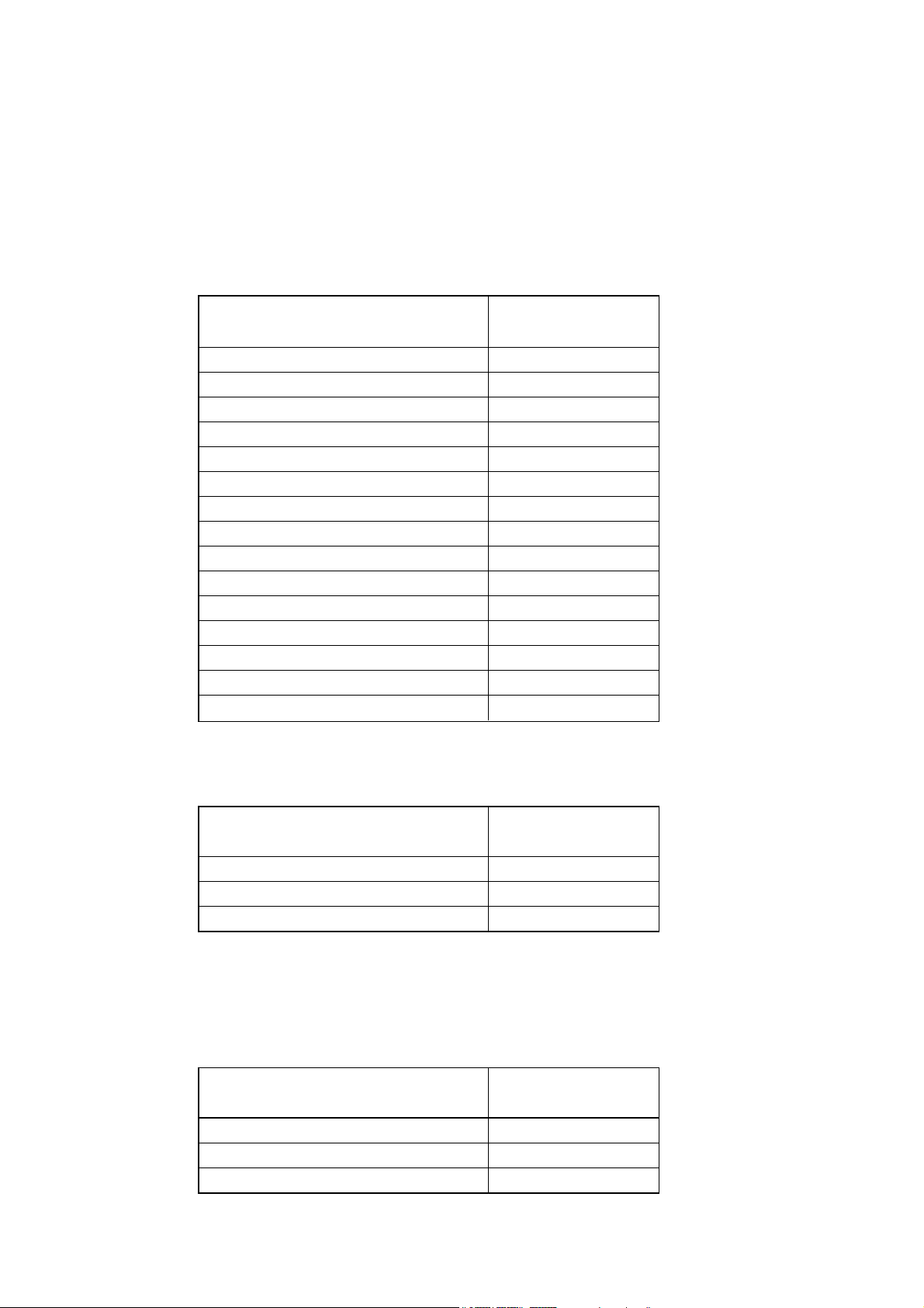
2.1. Complete Parts
2.2. Screws
2.3. Accessories Other Than Screws
Quantity
1
1
1
1
1
1
4
2
2
1
1
1
1
1
3
Part name
Top plate
Base
Front right frame
Front left frame
Rear right frame
Rear left frame
Side reinforcement bracket
Rear reinforcement bracket
Sub-frame
Top cover
Side cover (right)
Side cover (left)
Base cover (front)
Base cover (rear)
Rear cover
Quantity
60 (56)
20 (18)
30 (24)
Screw type
Bind head taptite screw type B 5 x 12
Bind head taptite screw type B 4 x 10
Bind head screw M4 x 8
( ) = Quantity to be actually used.
Quantity
2 (1.9 m or 6.23 ft)
8
20
Accessory
Screw cover
Screw cover rail
Cable tie
Page 5
5
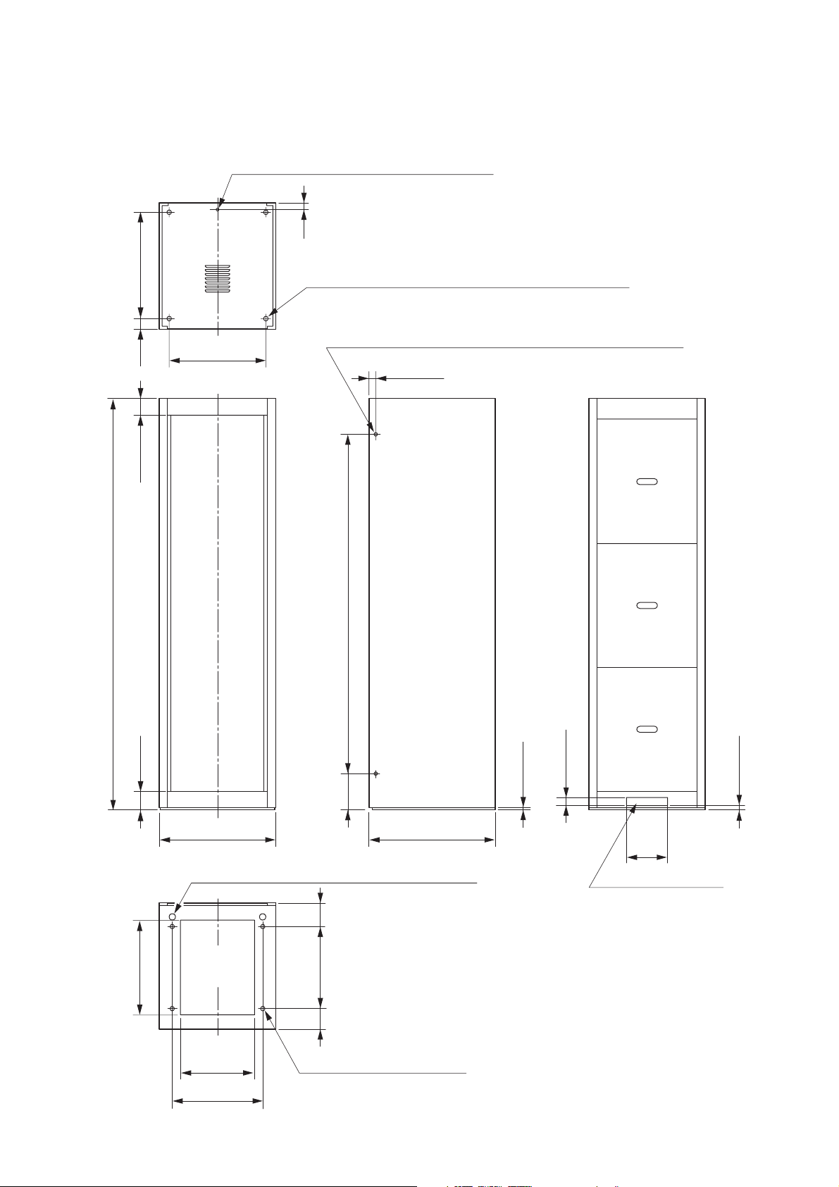
3. DIMENSIONAL DIAGRAMS
Mountable depth from the panel mounting surface is 590 mm (23.23"). (582 mm or 22.91" to rear
reinforcement bracket)
ø6.5 (0.26) Knockout hole for fixing to a wall
33 (1.3)
4-ø17.5 (0.69) Eyebolt mounting hole (with a hole plug)
518 (20.39)
4-ø12 (0.47) Knockout hole for securing multiple racks in line
51
(2.01)
82 (3.23)
470 (18.5)
33 (1.3)
2000 (78.74)
89 (3.5)
460
(18.11)
1649 (64.92)
175
(6.89)
566 (22.28)
Height adjustment screw (accessible from inside)
115
(4.53)
Cable entry
opening
360
(14.17)
400
(15.75)
100
(3.94)
4-ø15 (0.59) for anchor bolt
615 (24.21)
10 (0.39)
40 (1.57)
Cable entry opening
Unit: mm (inches)
20 (0.79)
200
(7.87)
440 (17.32)
Page 6
6
4. RACK ASSEMBLY
4.1. Cabinet Rack Assembly
Note
Be sure to check the name label ( ) attached to each part and the location of each part to be positioned
before assembly.
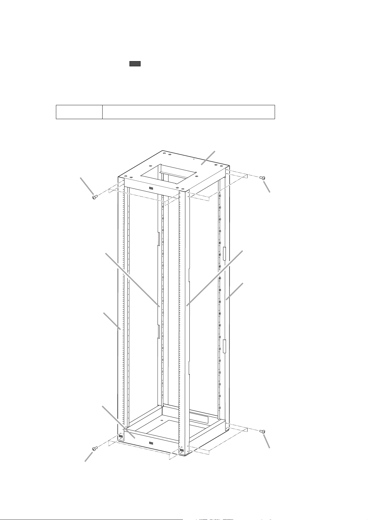
Step 1. Assemble the base, frames, and top plate.
Screws used
Bind head taptite screw type B 5 x 12 ..... 32 pieces
Bind head taptite screw type B 5 x 12
(Use the same type of screw
for the rear side.)
Rear left frame
Top plate
Bind head taptite screw type B 5 x 12
(Use the same type of screw
for the left side.)
Front right frame
Rear right frame
Front left frame
Base
Bind head taptite screw type B 5 x 12
(Use the same type of screw for the rear side.)
Bind head taptite screw type B 5 x 12
(Use the same type of screw
for the left side.)
Page 7

7
Step 2. Install the reinforcement brackets.
Screws used
Bind head taptite screw type B 5 x 12 ..... 24 pieces
Bind head taptite screw type B 5 x 12
(Use the same type of screw for the
lower rear reinforcement bracket.)
Rear reinforcement
brackets
Side reinforcement
brackets
Bind head taptite screw type B 5 x 12
(Use the same type of screw for the
upper and left side reinforcement brackets.)
Page 8

Step 3. Install the sub-frames.
Notes
• The name labels are not attached to the sub-frames. Also, there is no distinction between the left
and the right sub-frames.
• When using the supporting runners, the sub-frames must be installed.
Screws used
Bind head taptite screw type B 4 x 10 ..... 4 pieces
8
Sub-frames
Note
Use these screw holes to secure the
sub-frame. (Similarly to the left side)
Bind head taptite screw type B 4 x 10
Page 9

9
Step 4. Install the top and base covers.
Note
As a protection film is attached to each cover to prevent it from being scratched and stained, remove
it after installation completion.
Screws used
Bind head taptite screw type B 4 x 10 ..... 14 pieces
Bind head taptite screw type B 4 x 10
Top cover
Base cover (front)
Bind head taptite screw type B 4 x 10
Bind head taptite screw type B 4 x 10
Base cover (rear)
Page 10

10
Step 5. Install the side covers.
Note
As a protection film is attached to each cover to prevent it from being scratched and stained, remove
it after installation completion.
Screws used
Bind head screw M4 x 8 ..... 12 pieces
Side cover (right)
Bind head screw M4 x 8
Side cover (left)
Page 11

11
Step 6. Install the rear covers.
Note
As a protection film is attached to each cover to prevent it from being scratched and stained, remove
it after installation completion.
Screws used
Bind head screw M4 x 8 ..... 12 pieces
Bind head screw M4 x 8
Rear cover
Page 12

12
Note
To install the YA-706, use its second front hole
and rearmost hole as shown at right.
Step 2. Place the component on the loosely fitted YA-706, then
secure the component to the rack with the supplied rack
mounting screws.
Step 3. Lift up the loosely fitted YA-706 until it hold the component, then secure it.
4.2. YA-706 Supporting Runner (option) Installation
It is recommended that the optional Supporting Runner be installed to the rack so that the component can be
easily drawn from the front of the rack for maintenance purpose or if the strength is particularly needed when
installing the components in the rack.
The figures below show the way to install the YA-706 to the left side of the rack.
Follow the same procedure for installation to the right side.
Step 1. Fix the YA-706 loosely to the rack frame
and sub-frame.
Front left frame
Sub-frame
YA-706 (option)
Plain washer
(supplied with the YA-706)
Front
Bind head taptite screw type B4 x 10
(supplied with the YA-706)
YA-706
Front frame Sub-frame
Component
Rack mounting screw
Bind head taptite screw type B4 x 10
Note
Tighten the screws after securing
the component to the rack.
Page 13

13
4.3. BU-412 Blower Unit (option) Installation
The installation instructions are also printed on the BU-412 itself.
Step 1. Loosen 4 screws inside the top panel.
(No need to remove them.)
Step 2. Align the BU-412's front notches with the loosened front
screws, and rear notches with the rear screws.
Step 3. Tighten 4 loosened screws to secure the BU-412.
4.4. Screw Cover Installation
Install the screw covers after installation completion of all the components.
Eight screw cover fittings (4 each on both sides) are supplied with the unit.
Step 1. Loosen any rack mounting screw that holds the component, then insert the supplied screw cover
fitting into the gap exposed.
Notes
The component's front panel thickness may differ
depending on the model. In such cases, insert a
spacer between the screw cover fitting and
component’s front panel to align the height of all
screw cover fittings from the components’ panel
surfaces.
Top panel
Height of the screw cover fitting
from the panel surface
Screw cover fitting
(accessory)
Rack mounting
screw
Screw cover fitting
(accessory)
Component
Rack mounting screw
Component
Page 14

14
Step 2. Fit the supplied screw cover in the screw cover fittings.
4.5. 2202 Microphone Hanger (option) Installation
Install the optional 2202 Microphone Hanger to the rack's front frame to hang a handheld microphone.
Make holes in the desired position on the front frame referring to the figure below.
Note
Since no mounting screws are supplied with the microphone hanger, prepare two 4 x 10 tapping screws
separately.
Screw cover fitting attached to the component
Screw cover
(accessory)
(4 each on both sides)
[View with a microphone hung]
Microphone
Microphone hanger
[Mounting hole dimensional diagram
for the microphone hanger]
2-ø3.2 (0.13)
12.6 (0.5)
Unit: mm (inches)
Page 15

15
4.6. Cable Duct (commercial item) Installation
When running cables in a cable duct (commercial item), install the duct with the following procedures.
One each duct can be attached on both sides of the rear frames.
The following materials are required when installing the cable duct.
[Cable duct]
[Duct mounting plate]
Two duct mounting plates as shown below are required per duct.
[Screws and washer]
4 x 10 tapping screw ...................................................... 3 (per duct mounting plate)
Plain washer for M4
(outside diameter of approx. 16 mm or 0.63”) ................ 1 (per duct mounting plate)
Max. 1,830 mm (6 ft)
Max. 60 mm (2.36”)
Mounting side
Max. 30 mm (1.18”)
55 (2.17)
30 (1.18)15 (0.59)
40 (1.57)
64.5 (2.54)
20 (0.79)
44.5 (1.75)
Oval hole (for 4 mm screw)
Max. 30 mm (1.18”)
50 mm (1.97”)
pitch
Unit: mm (inches)
Plate thickness: 1.6 (0.06)
Material: Steel plate
Treatment: Chrome plated or painted
2-ø5 (0.2)5-ø3.5 (0.14)
Page 16

16
Step 1. Attach the duct mounting plates to the appropriate position on the rear frames.
Step 2. Install the cable ducts to the duct mounting plates.
Screws used
4 x 10 tapping screw ..... 3 (per duct mounting plate)
Plain washer ................. 1 (per duct mounting plate)
Notes
• The duct mounting plate cannot be mounted at the place of the supporting runner. To mount, keep the duct
mounting plate a bit apart from the runner, and attach it to the rear frame.
• Installing the cable duct reduces the mountable depth of the component to be installed in a rack to 540 mm
(1.77 ft) from the panel mounting surface.
4.7. Cable Binding
Bundle the cables of each component together using the supplied cable ties as shown below.
Rear
Rear frame
Duct mounting plate *
4 x 10 tapping screw *
Plain washer for M4 *
Cable duct *
1
2
4 x 10 tapping screw *
* Prepare separately.
Cable tie (accessory)
Rear frame
Rear
Cables
Page 17

17
5. CABINET RACK INSTALLATION
5.1. Installation
Keep spaces around the rack as shown below to facilitate maintenance and operation.
5.2. Securing to Floor
• 4-ø15 (0.59") anchor bolt holes are provided in the bottom surface of the base for securing the rack to the
floor.
• Secure the rack to the floor with M10 - M12 anchor bolts referring to the dimensions of the bottom surface of
the base as shown below.
Secure the rack to the floor with anchor bolts and to the wall with steel
brackets to prevent it from being toppled over by earthquakes, etc.
CAUTION
Wall surface
Over 0.6 m (1.97 ft)
Over 0.5 m (1.64 ft)
Over 2.0 m (6.56 ft)
CR-413-6
Front
Over 0.5 m (1.64 ft)
Space required for maintenance and operation
Front
115
(4.53)
Cable entry
opening
460 (18.11)
360 (14.17)
440 (17.32)
566 (22.28)
400 (15.75)
100
(3.94)
4-ø15 (0.59) for anchor bolts
Unit: mm (inches)
Page 18

18
5.3. Securing to a Wall
A ø6.5 mm (0.26”) knockout hole is provided in the top cover of the rack. (See page 5.)
Remove the knockout with a screwdriver, and secure the top cover to a wall using a bracket (separately
prepared).
[Example]
5.4. Securing Multiple Racks in Line
Two ø12 mm (0.47”) knockout holes are provided in each side cover. (See page 5.) When installing multiple
racks in line, remove these knockout holes with a screwdriver, then connect each adjacent racks using M8
bolts and nuts.
CR-413-6’s top cover
Bolt *
Bracket *
M6 bolt *
Anchor *
Knockout hole (ø6.5 mm or 0.26”)
Plain washer for M6 *
Nut for M6 *
* Prepare separately.
Page 19

19
5.5. Installing Eyebolts for Rack Suspension
Commercial suspension eyebolts can be installed on the top cover of the rack.
Note that following commercial parts are required.
M16 eyebolt ............................. 4
Nut for M16 .............................. 4
Plain washer for M16 ............... 4
Remove 4 hole plugs on the top cover, then install the eyebolts as illustrated below.
5.6. Making Fine Height Adjustment of Rack
If the rack installed on the floor is unstable or its top cover is not kept horizontal, make fine adjustment of its
height by turning the height adjustment screws on the bottom surface of the base (see page 5) using a
standard screwdriver.
5.7. Grounding
Use three M5 screws located at the back of the base for grounding.
Tip
Also, three M5 threaded holes are provided on the front of the base for your convenience.
Important
The total weight of the rack system that can be suspended must not exceed 300 kg (661.38 lb).
Remove 4 hole plugs.
CR-413-6’s top cover
M16 eyebolt
Plain washer for M16
Nut for M16
Page 20

URL: http://www.toa.jp/
 Loading...