

Page 1
OPERATING INSTRUCTIONS
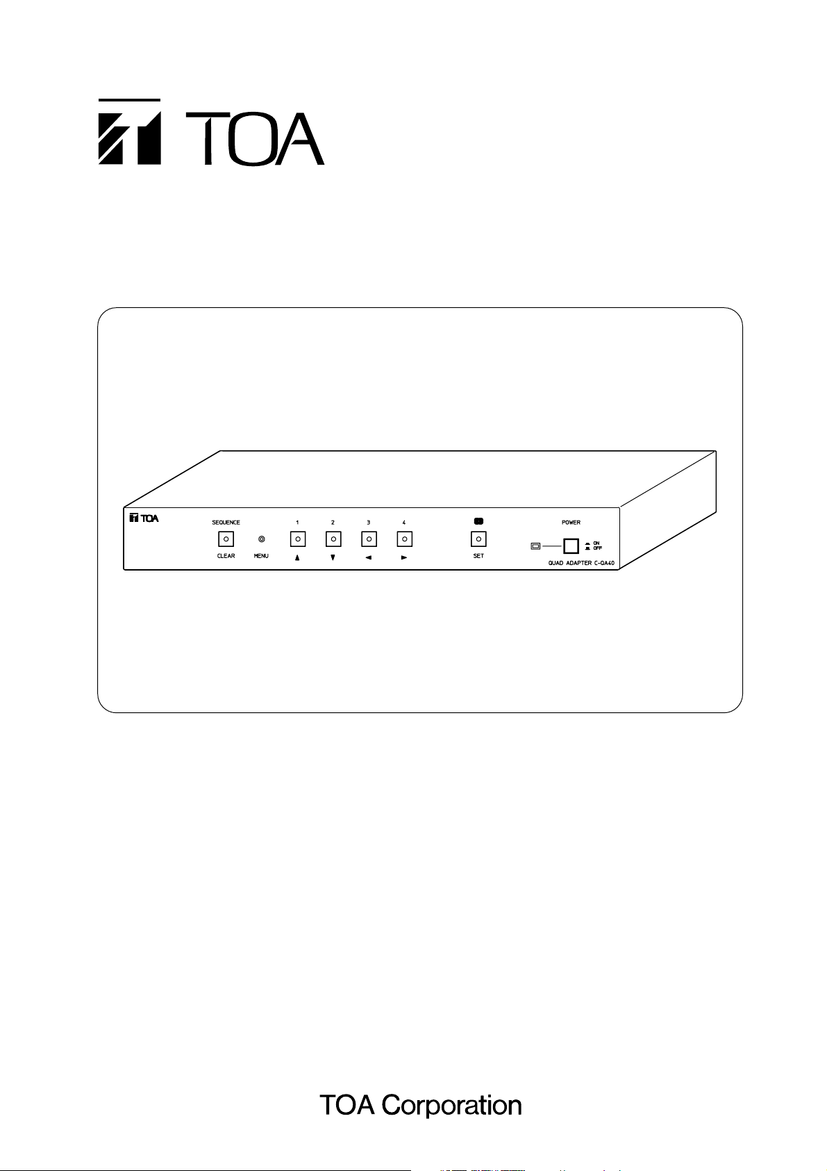
QUAD ADAPTER C-QA40
Please follow the instructions in this manual to obtain the optimum results from this unit.
We also recommend that you keep this manual handy for future reference.
Page 2

2
TABLE OF CONTENTS
1. SAFETY PRECAUTIONS ............................................................................... 3
2. GENERAL DESCRIPTION ............................................................................ 4
3. FEATURES ......................................................................................................... 4
4. NOMENCLATURE AND FUNCTIONS
Front ........................................................................................................................ 5
Rear ........................................................................................................................ 5
5. BASIC OPERATIONS
5.1. Switching on the Power ................................................................................... 6
5.2. Camera Image Selection (Monitor 2 Output Terminal) .................................... 6
5.3. Using the Alarm & Remote Functions .............................................................. 7
5.4. Freeze Screen Operations
5.4.1. Freezing the screen in a 4-segment split-screen display ....................... 8
5.4.2. Freezing a full-screen image .................................................................. 8
6. OPERATION MODE SETTINGS
6.1. Basic Setting Screen Operations
6.1.1. Setting screen display and operation ..................................................... 9
6.1.2. Setting screen mode termination ........................................................... 9
6.2. Menu/Setting Item Table ................................................................................. 10
6.3. Initial Setting ................................................................................................... 11
6.4. Performing Settings
1. Sequential Switching Settings [Sequence Switcher]) ................................. 11
1-1. Automatic Sequential Switching Time Interval Setting [Dwell Time] ... 12
1-2. Sequential Switching Skip Channel Setting [Sequence Skip] ............ 12
2. Title Display and Position Settings [Title Display] ....................................... 13
2-1. Full-screen Title Display Setting [Full Screen] .................................... 13
2-2. 4-Segment Split-Screen Title Display Setting [Quad Screen] ............. 14
2-3. Title Display Position Setting [Position] .............................................. 14
3. Title Setting [Title Setting] ........................................................................... 15
4. Alarm/Remote Setting [Alarm/Remote] ....................................................... 17
4-1. Alarm/Remote Signal Input Terminal Setting [Remote In] .................. 17
4-2. Alarm Contact Input Detection Polarity Setting [Input Contact] .......... 18
4-3. Alarm Operation Interval Setting [Duration] ........................................ 18
4-4. Operation Setting after the Alarm Interval Elapses [Auto Return] ...... 19
5. Others Settings [Condition] ......................................................................... 19
5-1. Monitor 1 Output Selection Setting [Monitor 1] ................................... 20
5-2. 4-Segment Split-Screen Border Display Setting [Frame] ................... 20
5-3. Background Color Setting [Back Color] .............................................. 21
5-4. Horizontal Screen Position Setting [H Offset] ..................................... 21
7. CONNECTION EXAMPLE
7.1. System Example ............................................................................................. 22
7.2. Alarm/Remote Signal Input Terminal Connection ........................................... 23
8. RACK MOUNTING .......................................................................................... 23
9. WHEN YOU THINK THERE IS A FAILURE ............................................ 24
10. SPECIFICATIONS ........................................................................................... 24
Accessory ............................................................................................................... 24
Page 3
When Installing the Unit
• Do not expose the unit to rain or an environment
where it may be splashed by water or other liquids,
as doing so may result in fire or electric shock.
• Use the unit only with the voltage specified on the
unit. Using a voltage higher than that which is
specified may result in fire or electric shock.
• Do not cut, kink, otherwise damage nor modify the
power supply cord. In addition, avoid using the
power cord in close proximity to heaters, and never
place heavy objects -- including the unit itself -- on
the power cord, as doing so may result in fire or
electric shock.
When the Unit is in Use
• Should the following irregularity be found during
use, immediately switch off the power, disconnect
the power supply plug from the AC outlet and
contact your nearest TOA dealer. Make no further
attempt to operate the unit in this condition as this
may cause fire or electric shock.
· If you detect smoke or a strange smell coming
from the unit.
· If water or any metallic object gets into the unit
· If the unit falls, or the unit case breaks
· If the power supply cord is damaged (exposure of
the core, disconnection, etc.)
· If it is malfunctioning (no image appears.)
• To prevent a fire or electric shock, never open nor
remove the unit case as there are high voltage
components inside the unit. Refer all servicing to
your nearest TOA dealer.
• Do not place cups, bowls, or other containers of
liquid or metallic objects on top of the unit. If they
accidentally spill into the unit, this may cause a fire
or electric shock.
• Do not insert nor drop metallic objects or
flammable materials in the ventilation slots of the
unit's cover, as this may result in fire or electric
shock.
• Do not touch the power supply plug during thunder
and lightning, as this may result in electric shock.
When Installing the Unit
• Never plug in nor remove the power supply plug
with wet hands, as doing so may cause electric
shock.
• When unplugging the power supply cord, be sure
to grasp the power supply plug; never pull on the
cord itself. Operating the unit with a damaged
power supply cord may cause a fire or electric
shock.
• When moving the unit, be sure to remove its power
supply cord from the wall outlet. Moving the unit
with the power cord connected to the outlet may
cause damage to the power cord, resulting in fire
or electric shock. When removing the power cord,
be sure to hold its plug to pull.
3
Indicates a potentially hazardous situation which, if mishandled, could
result in death or serious personal injury.
Indicates a potentially hazardous situation which, if mishandled, could
result in moderate or minor personal injury, and/or property damage.
WARNING
1. SAFETY PRECAUTIONS
• Be sure to read the instructions in this section carefully before use.
• Make sure to observe the instructions in this manual as the conventions of safety symbols and messages
regarded as very important precautions are included.
• We also recommend you keep this instruction manual handy for future reference.
Safety Symbol and Message Conventions
Safety symbols and messages described below are used in this manual to prevent bodily injury and property
damage which could result from mishandling. Before operating your product, read this manual first and
understand the safety symbols and messages so you are thoroughly aware of the potential safety hazards.
CAUTION
WARNING
CAUTION
Page 4

4
• Avoid installing the unit in humid or dusty locations,
in locations exposed to the direct sunlight, near the
heaters, or in locations generating sooty smoke or
steam as doing otherwise may result in fire or
electric shock.
When the Unit is in Use
• Do not place heavy objects on the unit as this may
cause it to fall or break which may result in
personal injury and/or property damage. In
addition, the object itself may fall off and cause
injury and/or damage.
• Contact your TOA dealer as to the cleaning. If dust
is allowed to accumulate in the unit over a long
period of time, a fire or damage to the unit may
result.
• If dust accumulates on the power supply plug or in
the wall AC outlet, a fire may result. Clean it
periodically. In addition, insert the plug in the wall
outlet securely.
• Switch off the power, and unplug the power supply
plug from the AC outlet for safety purposes when
cleaning or leaving the unit unused for 10 days or
more. A fire or electric shock may result.
2. GENERAL DESCRIPTION
TOA's C-QA40 Quad Adapter reduces the video images of up to 4 connected asynchronous color or blackand-white (B/W) cameras to quarter size, and displays these images on a monitor as a 4-segment split-screen
display.
3. FEATURES
• Up to four asynchronous cameras can be connected.
• Camera input "Loop Through" function facilitates combination with other systems.
• Both color and B/W cameras can be used together.
• High-precision 4-segment split-screen display.
• Two video outputs: 4-segment split-screen display output and key-selectable signal output.
• Alarm signal input terminals permit connection of movement sensors.
• Alarm signal output terminals permit connection of buzzers.
• Alarm features automatic reset function.
• Freeze function permits screen images to be stopped for closer inspection.
• Connected camera outputs can be automatically sequenced to the monitor at specified time intervals.
• Alphanumeric characters can be used for camera titles.
Page 5
5
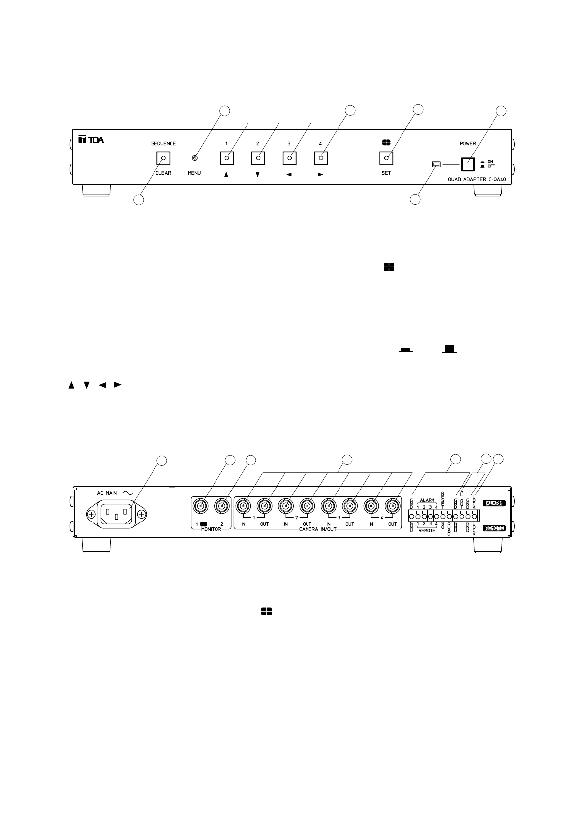
4. NOMENCLATURE AND FUNCTIONS
[Front]
1
2
3
4
5
6
1. Sequence/Clear Key
Sequentially switches the outputs of cameras 1-4
at set time interval (p. 12) for monitor display
through the Monitor 2 output terminal.
Pressing this key (its lamp lights) while the setting
screen is displayed returns the screen to the
previous setting screen. (If pressed while the
setting menu screen is displayed, the setting
screen mode is terminated.) (p. 9)
2. Menu Key
Displays and terminates the setting screen.
3. Channel Selector [1 – 4]/Cursor Control Keys
[ , , , ]
Pressing any one of these illuminated keys
transmits its corresponding channel image to the
Monitor 2 output terminal. When the setting screen
is displayed, these keys are also used to move the
cursor . (p. 9)
4. Quad Display [ ]/Setting Key
Pressing this illuminated key transmits the quad
display video signal to the Monitor 2 output
terminal. This key is also used to select and
register the setting item when the setting screen is
displayed. (p. 9)
5. Power Switch [ON /OFF ]
Press to switch ON or OFF power.
6. Power Lamp
Lights when the power is switched on.
[Rear]
7
8 9
10
11
12
13
7. AC Inlet
Insert the supplied power cable and connect to
the nearest available AC wall outlet.
8. Monitor 1 Output Terminal [MONITOR 1, ]
Used exclusively for 4-segment split screen
display. (75 Ω termination)
Can be synchronized with Monitor 2 terminal by
changing the setting. (Refer to p. 20 "Monitor 1
Output Selection Setting.")
9. Monitor 2 Output Terminal
Used for video signals (spot output) selected with
the front panel keys. Connect this terminal to the
monitor's video input terminal. (75 Ω termination)
10. Camera Video Input/Output Terminal
Connecting the camera video signal to this input
automatically terminates the internal impedance
at 75 Ω. When the camera video output is
connected to external equipment, the output
termination is automatically released.
11. Alarm/Remote Signal Input Terminals
For alarm signal input, remote control signal
input and ground. (Refer to p. 23.)
12. Alarm Signal Output Terminal
Outputs alarm signals when alarm is activated.
This terminal is an open collector output (12 V DC
and less than 30 mA). (Refer to p. 22.)
13. Key Input Disable Terminal
Front panel key (1 – 4) operations can be
disabled by connecting this terminal to the GND
terminal.
Page 6
6
5. BASIC OPERATIONS
Operating Precautions : Please read this manual carefully to avoid operation errors.
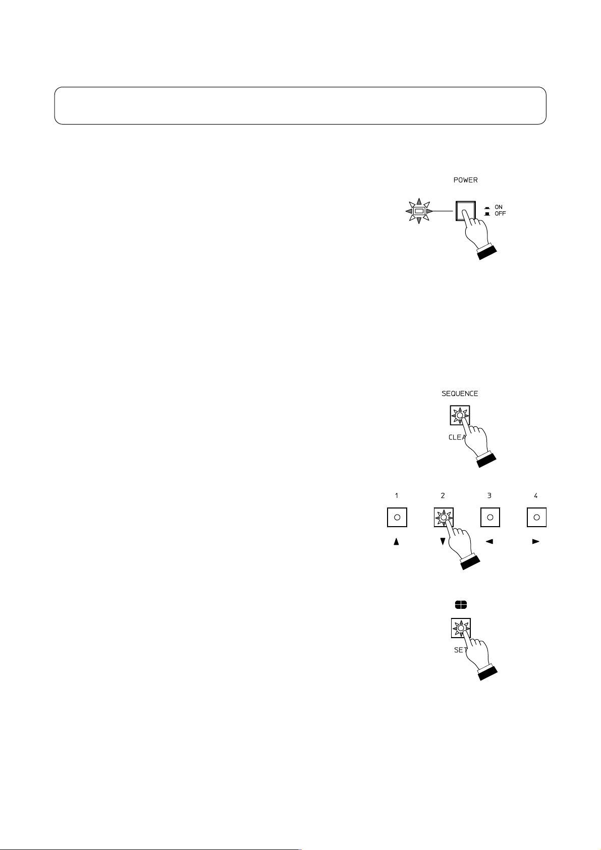
5.1. Switching on the Power
• Ensure that all connections, especially those of the power cables, are
secure.
• Switch ON the power by pressing the front panel Power switch, and
check to confirm that the power lamp lights. When the power is first
switched on, the video signal for automatic sequential switching is
output to the Monitor 2 output terminal by default.
• When finished with use, switch off the power and check to ensure that
the power lamp is extinguished.
Note
To prevent equipment failures and malfunction, do not remove or insert
the power cable when the power is on.
5.2. Camera Image Selection (Monitor 2 Output Terminal)
• Press the Sequence key and confirm that its indicator lamp lights. The
Quad Adapter will then be placed in automatic sequential switching
mode.
• Press the desired Channel Selector key (1 – 4) to select the camera
image for output to the Monitor 2 output terminal.
Important
Check to be sure that the camera image of the selected channel is
displayed on the monitor.
• Pressing the Quad Display key converts the camera images of
channels 1 – 4 into a 4-segment split-screen signal, and the signal is
output to the Monitor 2 output terminal.
Note
The Monitor 1 output terminal is factory-preset to continuously output 4segment split-screen images. If Monitor 1 is registered as [SYNCH] (Item
5-1. on p. 20), a desired image can be selected with the Sequence,
Channel Selector, or Quad Display keys. (Monitor 1 provides the same
operation as Monitor 2.)
Page 7

7
5.3. Using the Alarm & Remote Functions
• Select either "ALARM" or "REMOTE" in the Alarm/Remote settings shown on p. 17 (Item 4-1.).
• For Alarm operations, select either "Make" or "Break" to activate an alarm depending on the type of sensor
being connected (Item 4-2. on p. 18).
• Alarm duration can be selected from the variable interval of 1 – 60 seconds. Whether or not operation
automatically returns to the previous mode after the alarm interval elapses should also be set here.
• Connect the Alarm/Remote Signal Input terminals (p. 23).
• When the alarm is activated, the monitor display connected to the Monitor 2 output terminal is switched to
the alarm-activated camera scene accompanied by a flashing "ALARM" indication. The title of the alarmactivated camera channel also flashes on the monitor display connected to the Monitor 1 output terminal.
When an alarm is activated, the Alarm Signal output terminal is grounded via a transistor. (Use the
Alarm/Remote output terminals on 12 V DC and under 30 mA.)
• When the alarm is simultaneously activated in several camera channels, the alarm-activated channel
outputs are automatically sequenced to the monitor at one second intervals.
• The alarm can be reset by pressing the Channel Selector key, Sequence key, or Quad Display key (any key
other than the Menu key). It can also be reset by entering a reset signal from the Alarm/Remote input
terminals.
• Remotely-controlled operations perform the same function as when the front panel keys are operated.
Notes
• The alarm is disabled while the setting screen is displayed.
• The alarm signal output terminal cannot be used while the Remote input terminals are in use.
• The unit's rear panel QUAD terminal is only for remote control operation.
• All Alarm/Remote Signal Input Terminals are of edge type. Once the terminal is activated, it no longer is
activated again if not reset (i.e. in break when set for "make" detection, and in make when set for "break"
detection).
Page 8
8
5.4.2. Freezing a full-screen image
When Monitor 1 is set to synchronize with Monitor 2, only the Monitor 1 full-screen image can be frozen.
FREEZE
• To freeze the screen image currently displayed by pressing a Channel Selector key, press the same key
again. When in freeze mode, the selected key's indicator lamp flashes and the corresponding channel title
displayed on the monitor also flashes.
• While in Freeze mode, pressing the Channel Selector key of the frozen screen image disables the Freeze
mode.
• Pressing the Sequence key, Menu key or Quad Display key also disables the Freeze mode and performing
the relevant function.
Notes
• The Freeze mode is disabled when any setting screen is displayed or alarm activated.
• The "FREEZE" indication flashes while in Freeze mode unless the title has been set.
• Monitor 2 screen images cannot be frozen when in full-screen display mode.
FREEZE
• Press the Channel Selector key while holding down the Quad Display key. The selected key's indicator lamp
flashes and the corresponding channel title displayed on the monitor screen also flashes, indicating the
selected channel has been placed in Freeze mode.
• All 4 channels can be placed in Freeze mode by repeating the same operation.
• In Freeze mode, pressing any one of the Channel Selector keys 1 – 4 while holding down the Quad Display
key disables the Freeze mode of the corresponding channel.
• To simultaneously disable the Freeze mode of all channels, press any one of the Channel Selector keys (1 –
4).
Notes
• The Freeze mode is diabled for all channels when any setting screen is displayed or alarm is activated.
• The "FREEZE" indication flashes while the display is in Freeze mode unless the channel title has been set.
5.4. Freeze Screen Operations
5.4.1. Freezing the screen in a 4-segment split-screen display
Page 9

9
6. OPERATION MODE SETTINGS
6.1. Basic Setting Screen Operations
6.1.1. Setting screen display and operation
Press the Menu key using a mechanical pen or other pointed stuff. The screen will
then be switched to the setting screen display, and the menu screen will be displayed
on the monitor.
MENU
1 SEQUENCE SW I TCHER
2TITLEDISPLAY
3TITLESETTING
4ALARM/REMOTE
5 COND I T I ON
.
.
.
.
.
Setting Menu Screen
1. Sequential switcher setting
2. Title enable/indication position settings
3. Title character setting
4. Alarm/Remote function setting
5. Other settings
Setting items can be selected, setting contents determined, and the setting screen terminated using the front
panel keys.
Cursor Control Key [1]
Cursor Control Key [2]
Cursor Control Key [3]
Cursor Control Key [4]
Clear Key
Setting Key
Menu Key
Moves the cursor up one line and changes the setting contents.
Moves the cursor down one line and changes the setting contents.
Moves the cursor left one character and changes the setting contents.
Moves the cursor right one character and changes the setting contents.
Returns the display to a previous screen. (Terminates the setting screen
mode when pressed while the setting menu screen is displayed.)
Selects the item and registers the set contents.
Displays and terminates the setting screen.
Note
Be sure to use the Setting key when registering a setting change. If the Clear key is pressed to return the
display to a previous screen or if the setting screen is terminated with the Menu key before pressing the
Setting key, any setting changes will become invalid.
6.1.2. Setting screen mode termination
To terminate the setting screen mode, press the Menu key again or the Clear key
when the menu screen is displayed. The screen will then return to the mode it was in
just before the setting screen mode was entered.
Page 10

10
6.2. Menu/Setting Item Table
Sets the time interval to switch camera outputs in automatic
sequential switching mode.
Selects cameras to be automatically sequenced.
Sets whether or not the title is shown in a full-screen display.
Selts whether or not the title is shown in a 4-segment
split-screen display.
Sets whether to use the Alarm/Remote Signal input terminals
as the alarm input or remote input.
Sets the title display position.
Sets the title of each camera channel.
Sequential Switching Skip Channel (p. 12)
4-Segment Split-Screen Title Display (p. 14)
Title Display Position (p. 14)
Menu (p. 9)
Setting Menu
Screen
Menu Item
Setting Items and Setting Contents
Automatic Sequential Switching Time Interval (p. 12)
1. Sequence Switcher (p. 11)
Sets the alarm input terminals' detection polarity.
Sets an alarm operation time interval.
Sets whether or not to return the screen to the previous
operation after the set alarm time elapses.
Selects the border line color to be used in a 4-segment
split-screen display.
Selects the screen background color.
Sets the horizontal position in a 4-segment split-screen display.
Sets whether Monitor 1 is used for a 4-segment split-screen
display or synchronized with Monitor 2.
Alarm Contact Input Detection Polarity Setting (p. 18)
Alarm Operation Interval (p. 18)
Operation after the Alarm Interval Elapses (p. 19)
4-Segment Split-Screen Border Display (p. 20)
Background Color (p. 21)
Horizontal Screen Position (p. 21)
Full-Screen Title Display (p. 13)
3. Title Setting (p. 15)
2. Title Display (p. 13)
Alarm/Remote Signal Input Terminal (p. 17)
4. Alarm/Remote (p. 17)
Monitor 1 Output Selection (p. 20)
5. Condition (p. 19)
Page 11

11
6.3. Initial Setting
Setting Item Initial Setting
SEQUENCE
SWITCHER
DWELL TIME
SEQUENCE SKIP
FULL SCREEN
QUAD SCREEN
POSITION
CH1
CH2
CH3
CH4
REMOTE IN
CH1
CH2
CH3
CH4
QUAD
3SEC
OFF
OFF
OFF
OFF
ON
ON
ON
Upper left
Upper left
Upper left
Upper left
Upper row
Upper row
CH1
CH2
CH3
CH4
ALARM
MAKE
20SEC
ON
QUAD
GRAY
BLUE
Center
CH1
CH2
CH3
CH4
Quad (upper screens)
Quad (lower screens)
INPUT CONTACT
DURATION
AUTO RETURN
MONITOR 1
FRAME
BACK COLOR
H OFFSET
TITLE DISPLAY
TITLE SETTING
ALARM/REMOTE
CONDITION
Notes
• The alarm is disabled while the setting
screen is displayed.
• The settings are backed up for about
10 years.
6.4. Performing Settings
1. Sequential Switching Settings [Sequence Switcher]
Step 1. Using the [ ] and [ ] keys at the setting screen, move
the cursor to [1. SEQUENCE SWITCHER].
The selected item will then flash as shown in the figure
on the right.
Step 2. Press the Setting key, and the sequential switching
setting screen will be displayed.
Step 3. Perform the settings of items 1-1 and 1-2 shown below.
(p. 12)
MENU
1 SEQUENCE SW I TCHER
2TITLEDISPLAY
3TITLESETTING
4ALARM/REMOTE
5 COND I T I ON
.
.
.
.
.
Setting Menu Screen
SEQUENCE SW I TCHER
1DWELLTIME 3SEC
2SEQUENCESKIP
CH1 OF F
CH2 OF F
CH3 OF F
CH4 OF F
QUAD ON
.
.
Sequential Switching Setting Screen
1-1. Automatic sequential switching time interval setting
1-2. Sequential switching skip channel setting
[Setting screen termination]
Press the Clear key to exit the sequential switching setting
screen. The display then returns to the setting menu screen.
[Setting screen displays and operations]
Page 12

12
SEQUENCE SW I TCHER
1DWELLTIME 3SEC
2SEQUENCESKIP
CH1 OF F
CH2 OF F
CH3 OF F
CH4 OF F
QUAD ON
.
.
Sequential Switching Setting Screen
1-1. Automatic Sequential Switching Time Interval Setting [Dwell Time]
Step 1. Using the [ ] and [ ] keys at the sequential switching
setting screen, move the cursor to Item [1. DWELL
TIME].
The selected item will then flash.
Step 2. Press the Setting key, and the value entry area will
flash as shown in the figure on the right.
Step 3. Using the [ ] and [ ] keys, set a variable switching
interval of 1 – 60 seconds (in 1 second units).
Step 4. Press the Setting key to register the set value.
The display then returns to the mode in which the
setting item is highlighted.
SEQUENCE SW I TCHER
1DWELLTIME 3SEC
2SEQUENCESKIP
CH1 OF F
CH2 OF F
CH3 OF F
CH4 OF F
QUAD ON
.
.
Sequential Switching Setting Screen
1-2. Sequential Switching Skip Channel Setting [Sequence Skip]
Step 1. Using the [ ] and [ ] keys at the sequential switching
setting screen, move the cursor to the camera to skip.
The selected camera number will then flash.
Step 2. Press the Setting key, and the setting entry area will
flash as shown in the figure on the right.
Step 3. Using the [ ] and [ ] keys, select either ON*1or
OFF*2.
*1ON: The camera image is not displayed when in
automatic sequential switching mode.
*2OFF: The camera image is displayed when in
automatic sequential switching mode.
Step 4. Press the Setting key to register the set contents.
The display then returns to the mode in which the
setting item is flashing.
Step 5. Repeat Steps 1 – 4.
Step 6. Pressing the Clear key returns the display to the setting
menu screen.
Notes
• It is impossible to simultaneously set all individual cameras
[CH1] – [CH4] and [QUAD] to ON.
• Channels having no connected camera are skipped
regardless of the skip channel setting.
Page 13

13
2. Title Display and Position Settings [Title Display]
[Setting screen displays and operations]
Step 1. Using the [ ] and [ ] keys at the setting menu screen,
move the cursor to Item [2. TITLE DISPLAY].
The selected item will then flash as shown in the figure
on the right.
Step 2. Press the Setting key, and the Title Display setting
screen will be displayed.
Step 3. Perform the settings of the items 2-1, 2-2, and 2-3
shown below. (p. 13 – 15)
MENU
1 SEQUENCE SW I TCHER
2TITLEDISPLAY
3TITLESETTING
4ALARM/REMOTE
5 COND I T I ON
.
.
.
.
.
Setting Menu Screen
TITLE DISPLAY
1FULLSCREEN ON
2 QUAD SCREEN ON
3 POSITION CH1
CH2
CH3
CH4
QUAD
.
.
.
Title Display Setting Screen
2-1. Full-screen title display setting
2-2. 4-segment split-screen title display setting
2-3. Title display position setting
[Setting screen termination]
To exit the Title Display setting screen, press the Clear key. The
display then returns to the setting menu screen.
2-1. Full-screen Title Display Setting [Full Screen]
Step 1. Using the [ ] and [ ] keys at the Title Display setting
screen, move the cursor to Item [1. FULL SCREEN].
The selected item will then flash.
Step 2. Press the Setting key, and the setting entry area will
flash as shown in the figure on the right.
Step 3. Using the [ ] and [ ] keys, select either ON*1or
OFF*2.
*1ON: Displays the title on the full screen.
*2OFF: Displays no title on the full screen.
Step 4. Press the Setting key to register the set contents.
The display then returns to the mode in which the
setting item is flashing.
TITLE DISPLAY
1FULLSCREEN ON
2 QUAD SCREEN ON
3 POSITION CH1
CH2
CH3
CH4
QUAD
.
.
.
Title Display Setting Screen
Page 14

14
2-2. 4-Segment Split-Screen Title Display Setting [Quad Screen]
Step 1. Using the [ ] and [ ] keys at the Title Display setting
screen, move the cursor to Item [2. QUAD SCREEN].
The selected item will then flash.
Step 2. Press the Setting key, and the setting entry area will
flash as shown in the figure on the right.
Step 3. Using the [ ] and [ ] keys, select either ON*
1
or
OFF*2.
*1ON: Displays the title on the 4-segment split-screen.
*2OFF: Displays no title on the 4-segment split-screen.
Step 4. Press the Setting key to register the set contents.
The display then returns to the mode in which the
setting item is flashing.
TITLE DISPLAY
1FULLSCREEN ON
2 QUAD SCREEN ON
3 POSITION CH1
CH2
CH3
CH4
QUAD
.
.
.
Title Display Setting Screen
2-3. Title Display Position Setting [Position]
[Setting for cameras 1 – 4]
Step 1. Using the [ ] and [ ] keys at the Title Display setting
screen, move the cursor to the camera (1 – 4) for which
the title display position must be changed.
The selected camera number will then flash as shown
in the figure on the right.
Step 2. Pressing the Setting key displays the title display
position setting screen of the selected camera, and the
[ ] indication will flash at the title display
position.
Step 3. Select the display position (upper left, upper center,
upper right, lower left, lower center, or lower right)
using the [ ] and [ ] keys.
Step 4. Press the Setting key to register the selected position.
The display then returns to the Title display setting
screen.
Step 5. Pressing the Clear key returns the display to the setting
menu screen.
Note
When the title is displayed in any position in the upper row, the
alarm indication is displayed at the lower right, and at the upper
right when the title is displayed in the lower row.
TITLE DISPLAY
1FULLSCREEN ON
2 QUAD SCREEN ON
3 POSITION CH1
CH2
CH3
CH4
QUAD
.
.
.
Title Display Setting Screen
Title Display Position Setting Screen
Page 15

15
Step 1. Using the [ ] and [ ] keys at the Title Display setting
screen, move the cursor to [4. QUAD] for selection of
the title setting position.
The selected Quad indication will then flash.
Step 2. Press the Setting key.
The display is then switched to the 4-segment splitscreen, and two [ ] indications flash in the title
display positions for the two upper screens.
Step 3. Using the [ ] and [ ] keys, select either the upper or
lower display positions for either of the two upper or
lower screens.
Step 4. Press the Setting key to register the selected title
display positions for either the upper or lower screens.
The display then returns to the Title Display setting
screen.
Step 5. Repeat Steps 1 through 4 for selected position
registration if also changing the preset display positions
for the remaining two screens.
Step 6. Pressing the Clear key will return the display to the
setting menu screen.
TITLE DISPLAY
1FULLSCREEN ON
2 QUAD SCREEN ON
3 POSITION CH1
CH2
CH3
CH4
QUAD
.
.
.
Title Display Setting Screen
Title Display Position Setting Screen
[Setting for a 4-segment split-screen display]
MENU
1 SEQUENCE SW I TCHER
2TITLEDISPLAY
3TITLESETTING
4ALARM/REMOTE
5 COND I T I ON
.
.
.
.
.
Setting Menu Screen
3. Title Setting [Title Setting]
Step 1. Using the [ ] and [ ] keys while the setting menu
screen is displayed, move the cursor to Item [3. TITLE
SETTING].
The selected item will then flash.
Page 16

16
Step 2. Press the Setting key.
The Title Setting Camera Selection screen will then be
displayed, and the selectable camera number will flash
as shown in the figure on the right.
Step 3. Using the [ ] and [ ] keys, move the cursor to the
camera for which the title must be changed.
The display will then be switched to the selected
camera image.
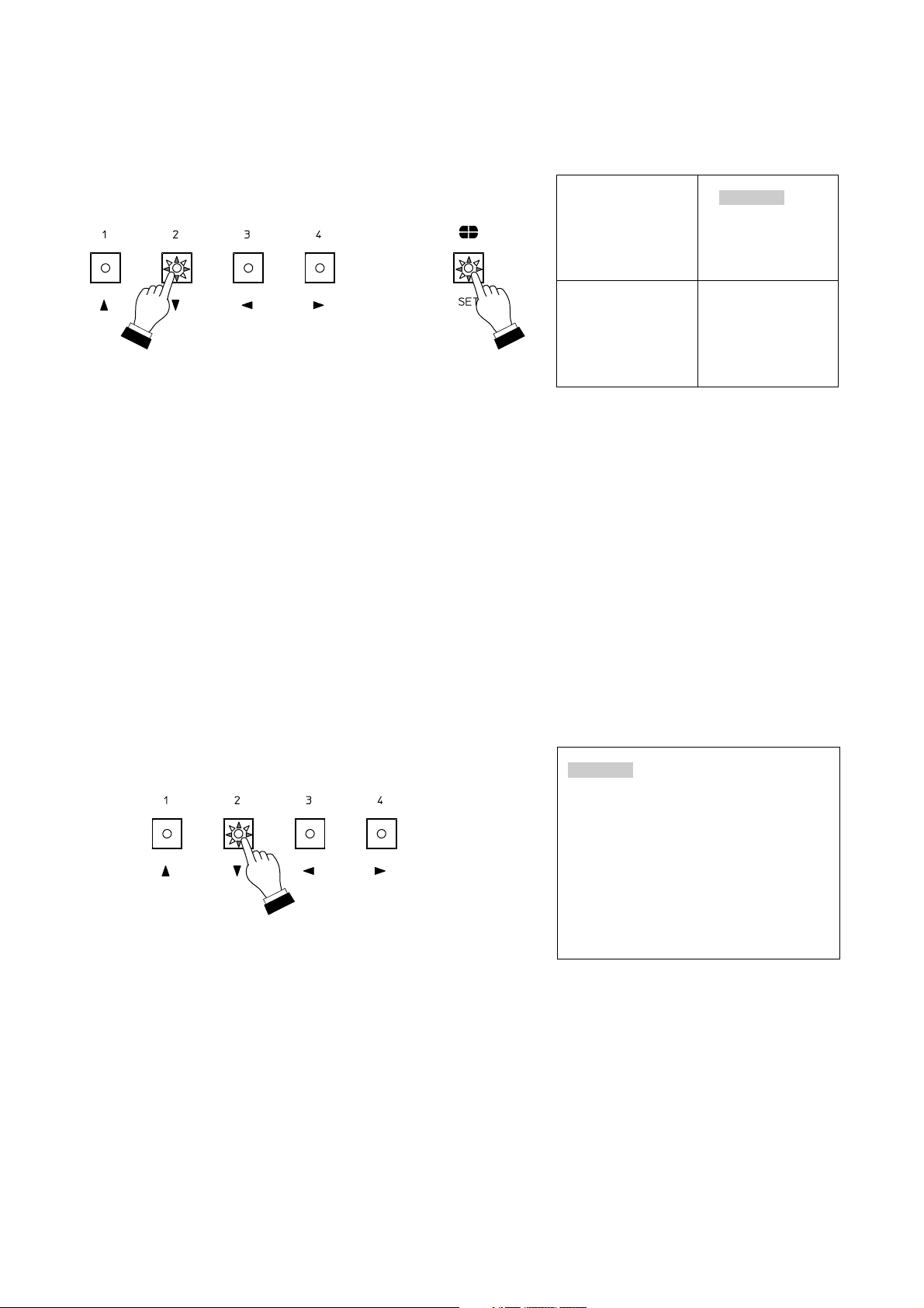
Step 4. Pressing the Setting key displays the character input
screen, in which the first character in the title display
line and character "A" in the character selection area
flash.
Step 5. Using the [ ], [ ], [ ], and [ ] keys, select a
character to enter.
The selected character will then flash.
Step 6. Press the Setting key after selection completion.
The selected character is displayed at the cursor
position in the title display line, and the cursor moves
right one character.
Step 7. Repeat Steps 5 and 6 to set the title (up to 8
characters).
Note
The selected characters are displayed at the cursor position in
the title display line. When entering the character to the position
not indicated by the cursor in the title display line to change or
add characters, move another cursor in the character selection
area to the [ ] or [ ] indication using the [ ], [ ], [ ], and
[ ] keys. The cursor in the title display line moves left or right
one character as the Setting key is pressed.
Step 8. After entering all characters, move the cursor in the
character selection area to the "SET" position using the
[ ], [ ], [ ], and [ ] keys. The Title Setting screen is
then terminated and the display returns to the Title
Setting Camera Selection screen.
Step 9. Pressing the Clear key returns the display to the setting
menu screen.
Note
When the cursor in the character selection area is placed in the
"CLEAR" position, if the Setting key is pressed, all title
characters are simultaneously erased. To erase part of the title,
move the cursor to the corresponding position in the title. After
moving the cursor in the character selection area to the
"SPACE" position, press the Setting key.
TITLE SETTING
1 CH1 CH1
2 CH2 CH2
3 CH3 CH3
4CH4 CH4
.
.
.
.
Title Setting Camera Selection Screen
SET TITLE CH1
CH1
SPACE CLEAR S ET
0123456789
ABCDEFGH I J KLM
NOPQRSTUVWX YZ
abcde fgh i j k lm
nopqrs t uvwx yz
!?/ ( )
:
.
,-&
Title Setting Input Screen
Page 17

17
4. Alarm/Remote Setting [Alarm/Remote]
[Setting screen display and operation]
Step 1. Using the [ ] and [ ] keys at the setting menu screen,
move the cursor to Item [4. ALARM/REMOTE].
The selected item will then flash as shown in the figure
on the right.
Step 2. Press the Setting key, and the Alarm/Remote setting
screen will be displayed.
Step 3. Perform the settings of the items 4-1 through 4-4
shown below. (p. 17 – 19)
MENU
1 SEQUENCE SW I TCHER
2TITLEDISPLAY
3TITLESETTING
4ALARM/REMOTE
5 COND I T I ON
.
.
.
.
.
Setting Menu Screen
[Setting screen termination]
To exit the Alarm/Remote setting screen, press the Clear key.
The display then returns to the setting menu screen.
ALARM /REMOTE
1REMOTE IN ALARM
2 INPUT CONTACT MAKE
3 DURAT I ON 20 SEC
4 AUTO RETURN ON
.
.
.
.
Alarm/Remote Setting Screen
4-1. Alarm/Remote signal input terminal setting
4-2. Alarm contact input detection polarity setting
4-3. Alarm operation interval setting
4-4. Operation setting after the alarm interval elapses
4-1. Alarm/Remote Signal Input Terminal Setting [Remote In]
Step 1. Using the [ ] and [ ] keys at the Alarm/Remote
setting screen, move the cursor to Item [1. REMOTE
IN].
The selected item will then flash.
Step 2. Press the Setting key, and the value entry area will
flash as shown in the figure on the right.
Step 3. Using the [ ] and [ ] keys, enter either ALARM*1or
REMOTE*2.
*1ALARM: Sets the rear panel terminal block for
alarm mode.
*2REMOTE: Sets the rear panel terminal block for
remote control mode.
Step 4. Press the Setting key to register the set contents.
The display then returns to the mode in which the
setting item is flashing.
Note
Entering "REMOTE" makes the contact input polarity a make
contact input, and the setting screens 4-2 through 4-4 are not
displayed.
ALARM /REMOTE
1REMOTE IN ALARM
2 INPUT CONTACT MAKE
3 DURAT I ON 20 SEC
4 AUTO RETURN ON
.
.
.
.
Alarm/Remote Setting Screen
Page 18

18
4-2. Alarm Contact Input Detection Polarity Setting [Input Contact]
Step 1. Using the [ ] and [ ] keys at the Alarm/Remote
setting screen, move the cursor to Item [2. INPUT
CONTACT].
The selected item will then flash.
Step 2. Press the Setting key, and the value entry area will
flash as shown in the figure on the right.
Step 3. Using the [ ] and [ ] keys, enter either MAKE*
1
or
BREAK*2.
*1MAKE: An alarm operates when the alarm contact
closes.
*2BREAK: An alarm operates when the alarm contact
opens.
Step 4. Press the Setting key to register the set contents.
The display then returns to the mode in which the
setting item is flashing.
Note
The contact input polarity can only be changed for the Alarm
Inputs 1-4. The Remote Inputs are always activated when
made.
ALARM /REMOTE
1REMOTE IN ALARM
2 INPUT CONTACT MAKE
3 DURAT I ON 20 SEC
4 AUTO RETURN ON
.
.
.
.
Alarm/Remote Setting Screen
4-3. Alarm Operation Interval Setting [Duration]
Step 1. Using the [ ] and [ ] keys at the Alarm/Remote
setting screen, move the cursor to Item [3.
DURATION].
The selected item will then flash.
Step 2. Press the Setting key, and the value entry area will
flash as shown in the figure on the right.
Step 3. Using the [ ] and [ ] keys, enter the alarm interval of
1 – 60 seconds (in 1 second units).
Step 4. Press the Setting key to register the set contents.
The display then returns to the mode in which the
setting item is flashing.
ALARM /REMOTE
1REMOTE IN ALARM
2 INPUT CONTACT MAKE
3 DURAT I ON 20 SEC
4 AUTO RETURN ON
.
.
.
.
Alarm/Remote Setting Screen
Page 19

19
4-4. Operation Setting after the Alarm Interval Elapses [Auto Return]
Step 1. Using the [ ] and [ ] keys at the Alarm/Remote
setting screen, move the cursor to Item [4. AUTO
RETURN].
The selected item will then flash.
Step 2. Press the Setting key, and the value entry area will
flash as shown in the figure on the right.
Step 3. Using the [ ] and [ ] keys, enter either ON*
1
or OFF*2.
*1ON: Operation returns to the mode the display was
in just before an alarm was activated after an
alarm interval elapses.
*2OFF: The same alarm-activated camera scene
continues to be displayed after the alarm
interval elapses.
Step 4. Press the Setting key to register the set contents.
The display then returns to the mode in which the
setting item is flashing.
ALARM /REMOTE
1REMOTE IN ALARM
2 INPUT CONTACT MAKE
3 DURAT I ON 20 SEC
4 AUTO RETURN ON
.
.
.
.
Alarm/Remote Setting Screen
5. Others Settings [Condition]
[Setting screen display and operation]
Step 1. Using the [ ] and [ ] keys at the setting menu screen,
move the cursor to Item [5. CONDITION].
The selected item will then flash as shown in the figure
on the right.
Step 2. Press the Setting key, and the "Others" setting screen
will be displayed.
Step 3. Perform the settings of the items 5-1 through 5-4
shown below. (p. 20 – 21.)
[Setting screen termination]
To exit the "Others" setting screen, press the Clear key.
The display then returns to the setting menu screen.
MENU
1 SEQUENCE SW I TCHER
2TITLEDISPLAY
3TITLESETTING
4ALARM/REMOTE
5 COND I T I ON
.
.
.
.
.
Setting Menu Screen
CONDITION
1 MON I TOR 1 QUAD
2 FRAME GRAY
3 BACK COLOR BLUE
4HOFFSET
.
.
.
.
Others Setting Screen
5-1. Monitor 1 output selection setting
5-2. 4-segment split-screen border display setting
5-3. Background color setting
5-4. Horizontal screen position setting
Page 20

20
5-1. Monitor 1 Output Selection Setting [Monitor 1]
Step 1. Using the [ ] and [ ] keys at the Others setting
screen, move the cursor to Item [1. MONITOR 1].
The selected item will then flash.
Step 2. Press the Setting key, and the value entry area will
flash as shown in the figure on the right.
Step 3. Using the [ ] and [ ] keys, enter either QUAD*
1
or
SELECT*2.
*1QUAD: Sets Monitor 1 for 4-segment split-screen
display output.
*2SELECT: Screen images are switched by front
panel key operation or remote control
operation as with Monitor 2.
Step 4. Press the Setting key to register the set contents.
The display then returns to the mode in which the
setting item is flashing.
CONDITION
1 MON I TOR 1 QUAD
2 FRAME GRAY
3 BACK COLOR BLUE
4HOFFSET
.
.
.
.
Others Setting Screen
5-2. 4-Segment Split-Screen Border Display Setting [Frame]
Step 1. Using the [ ] and [ ] keys at the Others setting
screen, move the cursor to Item [2. FRAME].
The selected item will then flash.
Step 2. Press the Setting key, and the value entry area will
flash as shown in the figure on the right.
Step 3. Using the [ ] and [ ] keys, enter GRAY*1or BLACK*
2
or OFF*3.
*1GRAY: A gray border line is displayed in a 4-
segment split-screen display.
*2BLACK: A black border line is displayed in a 4-
segment split-screen display.
*3OFF: No border line is displayed in a 4-segment
split-screen display.
Step 4. Press the Setting key to register the set contents.
The display then returns to the mode in which the
setting item is flashing.
CONDITION
1 MON I TOR 1 QUAD
2 FRAME GRAY
3 BACK COLOR BLUE
4HOFFSET
.
.
.
.
Others Setting Screen
Page 21

21
5-3. Background Color Setting [Back Color]
Step 1. Using the [ ] and [ ] keys at the Others setting
screen, move the cursor to Item [3. BACK COLOR].
The selected item will then flash.
Step 2. Press the Setting key, and the value entry area will
flash as shown in the figure on the right.
Step 3. Using the [ ] and [ ] keys, enter either BLUE*
1
or
BLACK*2.
*1BLUE: The blue background is displayed when
video loss (no signal transmission from the
connected camera) occurs.
*2BLACK: The black background is displayed when
video loss occurs.
Step 4. Press the Setting key to register the set contents.
The display then returns to the mode in which the
setting item is flashing.
Notes
• No back ground color is displayed on the screen connected to
Monitor 2 when all of the following conditions simultaneously
take place (the screen becomes dark):
• Monitor 1 is set for "QUAD."
• The screen is set for a full-screen display.
• There are one or more channels without "Video loss."
• The background of the setting menu screen is always blue
regardless of the background color setting.
CONDITION
1 MON I TOR 1 QUAD
2 FRAME GRAY
3 BACK COLOR BLUE
4HOFFSET
.
.
.
.
Others Setting Screen
5-4. Horizontal Screen Position Setting [H Offset]
Step 1. Using the [ ] and [ ] keys at the Others setting
screen, move the cursor to Item [4. H OFFSET].
The selected item will then flash.
Step 2. Press the Setting key, and the horizontal position
adjustment screen will be displayed.
Step 3. A vertical line moves as the [ ] and [ ] keys are
pressed. Adjust the horizontal screen position to the
appropriate position.
Step 4. Press the Setting key to register the set position.
The display then returns to the mode in which the
setting item is flashing.
CONDITION
1 MON I TOR 1 QUAD
2 FRAME GRAY
3 BACK COLOR BLUE
4HOFFSET
.
.
.
.
Others Setting Screen
Horizontal Position Adjustment Screen
Page 22

22
7. CONNECTION EXAMPLE
7.1. System Example
Make connections referring to the following connection diagram.
Wiring Precautions
• Connect the power cable after completing all equipment connections.
• Ensure that the unit's power is switched OFF before connecting the power cable.
• Do not apply the voltage to the unit's individual video inputs and output terminals.
• When black-and-white cameras are connected, monitor displays may become slightly colored.
• When line-locked cameras are connected, video images may be distorted. In such cases, switch the camera
synchronization system to internal synchronization mode.
Monitor TV
Monitor TV
Monitor TV
: BNC connector (optional)
Single-cable camera
C-QA40
C-QA40
Separate room
Camera Drive Unit
VIDEO IN
VIDEO IN
VIDEO IN
VCR
IN IN IN IN
OUT OUT OUT OUT
CAMERA OUT
CAMERA OUT
CAMERA OUT
CAMERA OUT
GND
Alarm input
Camera 1
Camera 2
Camera 3
Camera 4
Tab
Input 1
Input 2
Input 3
Input 4
Monitor 1
Input 1
Input 2
Input 3
Input 4
Output 1
Output 2
Output 3
Output 4
Monitor 1
Monitor 2
Alarm output
(For connection,
refer to p. 23.)
Insert a cable
pushing in the tab
with a screwdriver
blade.
GND
Page 23

23
7.2. Alarm/Remote Signal Input Terminal Connection
Capacitors of
0.01– 0.1 µF
Alarm/Remote inputted
Make connections referring to the
following wiring diagram.
• Select either Alarm or Remote in "4-1. Alarm/Remote
Signal Input Terminal Setting [Remote In]" on the setting
screen. (p. 17)
• Alarm is activated or remote control is performed by
opening or closing between the signal input terminal and
grounding terminal using a no-voltage contact pulse.
• Contact input polarity setting
"Alarm" setting: Alarm is activated when the contact
closes if MAKE is selected, and when
the contact opens if BREAK is selected.
"Remote" setting: Remote control operation is always
performed when the contact closes.
[Input signal specifications]
Alarm/remote input signal pulse width: Over 0.3 second
Alarm/remote input signal pulse separation: Over 0.3 second
Notes
• Do not apply the voltage to the Alarm/remote signal input
terminals.
• Avoid connecting the Alarm/remote signal input terminals
to the channel not connected to a camera.
• Mount a 0.01 – 0.1 µF ceramic capacitor across the input
and switch when installing the unit in the high noise level
area.
8. RACK MOUNTING
When mounting the unit in an equipment rack, remove bottom plate rubber feet, then mount as shown below
using an optional MB-QA40 mounting kit.
Page 24

133-12-658-10
10. SPECIFICATIONS
Power Source 110 – 240 V AC, 50/60 Hz
Power Consumption 7 W
Camera Input VBS 1.0 V(p-p), 75 Ω, BNC, 4 channels (asynchronous, with Loop Through
output)
Video Output VBS 1.0 V(p-p), 75 Ω, BNC, 2 channels
Monitor 1: 4-segment split-screen display or display selected with Monitor 2
Monitor 2: Full-screen/4-segment split-screen display or sequential switching
(4-segment split-screen image: Real-time display)
External Control Input Alarm/remote input signal pulse width: Over 0.3 second
and Output Alarm input: 1, 2, 3, 4, alarm reset (shared with Remote Input)
Activation by no-voltage contact input to between alarm
signal input terminal and grounding terminal*
Remote input: 1, 2, 3, 4, sequential switching, QUAD mode
Activation by no-voltage contact input to between remote
signal input terminal and grounding terminal*
Remote operation: Remote control of individual front panel keys (edge type
last-in-first-out priority)
Alarm output: Open collector output, 12 V DC, under 30 mA
Title Display Up to 8 alphanumeric characters for each channel
Synchronizing System Internal synchronization
Automatic Sequential Automatic switching interval: 1 – 60 seconds, Skip function (selection for each
Switching input)
Operating Temperature 0 – 40°C
Operating Humidity 30 – 90% (no due condensation must be formed)
Range
Finish Panel: ABS resin, black, paint
Case: Pre-coated steel plate, black
Dimensions 350 (w) x 44 (h) x 298 (d) mm (except protrusion)
Weight 2.5 kg
* Refer to p. 23 "Alarm/Remote Signal Input Terminal Connection."
Note: The design and specifications are subject to change without notice for improvement.
• Accessory
Power cord (2 m) ........................................ 1
9. WHEN YOU THINK THERE IS A FAILURE
No image is displayed.
Symptom
Noise appears on screen image.
Neither remote input nor alarm input
operates correctly.
Cause
Power cable is not connected to AC wall outlet.
Power switch is not set to ON position.
No video signal input from camera.
Monitor output is not correctly connected to monitor.
Camera's coaxial cable is not correctly connected.
Power cable is installed in close proximity to camera's coaxial cable.
Signal remains applied to the input terminal.
Cable is not correctly connected.
Noise exists in cable.
Input detection polarity is not correctly set.
•
•
•
•
•
•
•
•
•
•
 Loading...