

Page 1

INSTALLATION AND
OPERATING INSTRUCTIONS
(Applicable to the 9000M2
firmware Ver. 2.00 or later)
9000 Series Power Amplifier
Dual CH 500W Digital Mixing Amplifier
CP-9500M2-EB
A-9500D2-AS 1CE
Please also read the separate instruction manual for the programming software in conjunction
with this manual.
Thank you for purchasing TOA's 9000 series Amplifier.
Please carefully follow the instructions in this manual to ensure long, trouble-free use of your equipment.
Note:All the 9000 series in this manual refer to CP-9500M2-EB and A-9500D2-AS 1CE.
Page 2

TABLE OF CONTENTS
1. IMPORTANT SAFETY INSTRUCTIONS ................................................................ 6
2. SAFETY PRECAUTIONS
3. GENERAL DESCRIPTION
............................................................................................ 7
.......................................................................................... 9
4. FEATURES .....................................................................................................................10
5. INSTALLATION PRECAUTIONS
6. HANDLING PRECAUTIONS
.............................................................................11
.....................................................................................11
7. NOMENCLATURE AND FUNCTIONS(EXAMPLE FOR CP-9500M2-EB)
7.1. CP-9500M2-EB Amplifier
[Front] ...........................................................................................................................12
[VFD on-screen indications] .........................................................................................13
[Changing the indicated channels on the LEVEL output meter] ...................................15
[Changing the input and output meter display status] ..................................................15
[Rear] ...........................................................................................................................16
7.2. Optional Modules
7.2.1. D-001T and D-001R (2-channel Input Modules) ................................................17
7.2.2. T-001T (Audio Output Expansion Module) .........................................................17
7.2.3. ZP-001T (Zone Paging Module) .........................................................................18
7.2.4. C-001T (Control I/O Expansion Module) ............................................................19
7.2.5. AN-001T (Ambient Noise Sensor Input Module) ................................................19
7.2.6. RC-001T (Remote Control Module) ...................................................................20
7.3. Optional Accessories
7.3.1. AN-9001 (Ceiling Mount Microphone) ................................................................21
7.3.2. ZM-9001 (Zone Manager) ..................................................................................22
7.3.3. ZM-9002 (Zone Manager) ..................................................................................23
7.3.4. ZM-9003 (Zone Manager) ..................................................................................24
7.3.5. ZM-9011 (Remote Control Panel) ......................................................................25
7.3.6. ZM-9012 (Remote Control Panel) ......................................................................26
7.3.7. ZM-9013 (Remote Control Panel) ......................................................................27
7.3.8. ZM-9014 (Remote Control Panel) ......................................................................28
7.3.9. SS-9001 (Speaker Selector) ..............................................................................30
8. OPERATION OUTLINE
8.1. Using as a Mixer Amplifier ............................................................................................31
8.2. Using as a Paging Amplifier .........................................................................................32
8.2.1. Paging using the D-001T, D-001R, or 900 series module ................................ 32
8.2.2. Paging using the ZP-001T module .................................................................... 33
8.2.3. Cross point ON/OFF control using the remote controller .................................. 36
8.3. Glossary ...................................................................................................................... 40
2
Page 3

9. OPERATION
9.1. Basic Operation
9.1.1. Keys and knobs ..................................................................................................43
9.1.2. Power ON/OFF ..................................................................................................43
9.1.3. Changing the input parameters ..........................................................................43
9.1.4. Changing the output parameters ........................................................................44
9.1.5. Input channel ON/OFF .......................................................................................44
9.1.6. Output channel ON/OFF ....................................................................................44
9.2. Recalling Scene Memory .............................................................................................45
9.3. Making Zone Paging
9.3.1. Zone paging using the D-001T, D-001R, or 900 series module .........................46
9.3.2. Zone paging using the ZP-001T module ............................................................48
9.4. Releasing Key Lock ......................................................................................................50
9.5. Operation Example .......................................................................................................51
10. SETTINGS
10.1. Setting Menu Configuration and Flow for Entering Each Screen
10.1.1. Input setting configuration ..............................................................................52
10.1.2. Output setting configuration ...........................................................................52
10.1.3. Utility setting configuration .............................................................................53
10.1.4. Scene memory setting configuration ..............................................................53
10.1.5. Confirming set items ......................................................................................53
10.2. Input Setting Flow Chart
10.2.1.
10.2.2. Input setting flow chart for the channel on which the ZP-001T is used ..........56
10.2.3. Input setting flow chart for the channel on which the AN-001T is used ........57
10.2.4. Input setting items ..........................................................................................58
10.3. Output Setting Flow Chart ..........................................................................................69
10.3.1. Output setting items .......................................................................................70
10.4. UTILITY Setting Flow Chart .......................................................................................75
10.4.1. Control input terminal's function settings ........................................................77
10.4.2. Control output terminal's function settings .....................................................77
10.4.3. Utility setting items .........................................................................................78
10.5. Key Lock Function Setting
10.5.1. Keys that can be locked .................................................................................90
10.5.2. Password setting ............................................................................................91
10.5.3. Key lock setting operation ..............................................................................92
10.6. SCENE MEMORY Setting Flow Chart ........................................................................93
10.6.1. Scene memory setting items ..........................................................................94
Input setting flow chart for the channel
on which the D-001T or D-001R is used
..........................................................54
11. HOW TO STORE OR ERASE SCENE MEMORY
11.1. Recalling Scene Memory ...........................................................................................96
11.2. Storing Scene Memory ...............................................................................................97
11.3. Erasing Scene Memory ..............................................................................................98
11.4. Setting the Scene Memory to be Recalled at Power-On ............................................99
3
Page 4

12. RESTORING FACTORY DEFAULT SETTING
12.1. Default Setting Table
12.1.1. Items regarding system settings ................................................................. 101
12.1.2. Items regarding Scene settings ................................................................... 103
12.1.3. Items regarding paging settings .................................................................. 105
..................................................100
13. MODULE INSTALLATION
13.1. Module Combination ................................................................................................106
13.2. Channel Numbers and Terminal Numbers ...............................................................106
13.3. Module Installation ...................................................................................................106
13.4. Module Installation Examples ...................................................................................108
14.CONNECTIONS(EXAMPLE FOR CP-9500M2-EB)
14.1. Control I/O Terminal Connections
14.1.1. When a variable resistor or variable DC power supply unit is connected ....109
14.1.2. When the ZM-9001 or ZM-9002 is connected ..............................................110
14.1.3. When the ZM-9003 is connected .................................................................110
14.1.4. When the SS-9001 is connected ..................................................................110
14.1.5. Operation by control input ............................................................................111
14.2. Speaker Output Terminal Connections
14.3. C-001T Module Connections
14.3.1. Control input terminal ...................................................................................112
14.3.2. Control output terminal .................................................................................112
14.3.3. Connecting the ZM-9003 ..............................................................................113
14.3.4. Connecting the SS-9001 ..............................................................................113
14.4. RC-001T Module Connection
14.4.1. Connection method ......................................................................................114
14.4.2. Cable distance .............................................................................................115
14.5. RS-232C Connector Connection ..............................................................................118
14.6. AN-001T and AN-9001 Connections ........................................................................118
14.7. Power Source Connections to the SS-9001
14.7.1. When using a 24 V DC power source ..........................................................119
14.7.2. When using the optional AC adapter ...........................................................119
14.8. Removable Terminal Plug Connection .....................................................................120
....................................................................112
15. RACK MOUNTING BRACKET ATTACHMENT
16. CLEANING THE FILTER
17. AN-9001 INSTALLATION
..........................................................................................122
.........................................................................................123
................................................121
18. DIMENSIONAL DIAGRAMS
18.1. AN-9001 ...................................................................................................................124
18.2. ZM-9001 ...................................................................................................................125
18.3. ZM-9002 ...................................................................................................................125
18.4. ZM-9003 ...................................................................................................................126
18.5. ZM-9011 ...................................................................................................................127
18.6. ZM-9012 ...................................................................................................................127
18.7. ZM-9013 ...................................................................................................................128
18.8. ZM-9014 ...................................................................................................................129
18.9. SS-9001 ...................................................................................................................130
4
Page 5

19. OUTLINE OF THE ATTACHED SOFTWARE
....................................................131
20. ERROR INDICATIONS
21. TROUBLESHOOTING
22. BLOCK DIAGRAM
23. SIGNAL FLOW DIAGRAM
24. LEVEL DIAGRAM
..............................................................................................132
..............................................................................................133
.....................................................................................................134
......................................................................................135
.......................................................................................................136
25. COMPRESSION CHARACTERISTICS DIAGRAM
26. SPEAKER PRESET PARAMETER LIST
............................................................138
27. SPECIFICATIONS
27.1. CP-9500M2-EB AND A-9500D2-AS 1CE
27.2. Optional Modules
27.2.1. D-001T .........................................................................................................145
27.2.2. D-001R .........................................................................................................146
27.2.3. T-001T ..........................................................................................................147
27.2.4. C-001T .........................................................................................................148
27.2.5. ZP-001T .......................................................................................................148
27.2.6. AN-001T .......................................................................................................149
27.2.7. RC-001T .......................................................................................................149
27.3. Optional Accessories
27.3.1. AN-9001 .......................................................................................................150
27.3.2. ZM-9001 .......................................................................................................150
27.3.3. ZM-9002 .......................................................................................................151
27.3.4. ZM-9003 .......................................................................................................151
27.3.5. ZM-9011 .......................................................................................................152
27.3.6. ZM-9012 .......................................................................................................152
27.3.7. ZM-9013 .......................................................................................................153
27.3.8. ZM-9014 .......................................................................................................153
27.3.9. SS-9001 .......................................................................................................154
.............................................................. 142
..........................................137
5
Page 6

1. IMPORTANT SAFETY INSTRUCTIONS
• Read these instructions.
• Keep these instructions.
• Heed all warnings.
• Follow all instructions.
• Do not use this apparatus near water.
• Clean only with dry cloth.
• Do not block any ventilation openings. Install in accordance with the manufacturer's instructions.
• Do not install near any heat sources such as radiators, heat registers, stoves, or other apparatus (including
amplifiers) that produce heat.
• Do not defeat the safety purpose of the polarized or grounding-type plug. A polarized plug has two blades
with one wider than the other. A grounding type plug has two blades and a third grounding prong. The wide
blade or the third prong are provided for your safety. If the provided plug does not fit into your outlet, consult
an electrician for replacement of the obsolete outlet.
• Protect the power cord from being walked on or pinched particularly at plugs, convenience receptacles, and
the point where they exit from the apparatus.
• Only use attachments/accessories specified by the manufacturer.
• Use only with the cart, stand, tripod, bracket, or table specified by the manufacturer,
or sold with the apparatus. When a cart is used, use caution when moving the
cart/apparatus combination to avoid injury from tip-over.
• Unplug this apparatus during lightning storms or when unused for long periods of time.
• Refer all servicing to qualified service personnel. Servicing is required when the apparatus has been
damaged in any way, such as power-supply cord or plug is damaged, liquid has been spilled or objects have
fallen into the apparatus, the apparatus has been exposed to rain or moisture, does not operate normally, or
has been dropped.
6
Page 7
2. SAFETY PRECAUTIONS
• Before installation or use, be sure to carefully read all the instructions in this section for correct and safe
operation.
• Be sure to follow all the precautionary instructions in this section, which contain important warnings and/or
cautions regarding safety.
• After reading, keep this manual handy for future reference.
Safety Symbol and Message Conventions
Safety symbols and messages described below are used in this manual to prevent bodily injury and property
damage which could result from mishandling. Before operating your product, read this manual first and
understand the safety symbols and messages so you are thoroughly aware of the potential safety hazards.
The exclamation point within an equilateral triangle is intended to alert the user to the presence of
important operation and maintenance (servicing) instruction in the literature accompanying the
appliance.
Indicates a potentially hazardous situation which, if mishandled,
WARNING
When Installing the Unit
could result in death or serious personal injury.
• Do not expose the unit to rain or an environment where it may be splashed by water or other liquids, as
doing so may result in fire or electric shock.
• Use the unit only with the voltage specified on the unit. Using a voltage higher than that which is specified
may result in fire or electric shock.
• Do not cut, kink, otherwise damage nor modify the power supply cord. In addition, avoid using the power
cord in close proximity to heaters, and never place heavy objects -- including the unit itself -- on the power
cord, as doing so may result in fire or electric shock.
• Avoid installing or mounting the unit in unstable locations, such as on a rickety table or a slanted surface.
Doing so may result in the unit falling down and causing personal injury and/or property damage.
• External wiring connected to the terminals marked with requires installation by an instructed person.
• The apparatus shall be connected to a mains socket outlet with a protective earthing connection.
• The socket-outlet shall be installed near the equipment and the plug shall be easily accessible.
• Use the supplied rack mounting bracket when mounting the unit in an equipment rack. Remove four M4 x 8
screws on both sides of the unit, and mount the bracket there using the supplied M4 x 16 screws instead.
When the Unit is in Use
• Should the following irregularity be found during use, immediately switch off the power, disconnect the power
supply plug from the AC outlet and contact your nearest TOA dealer. Make no further attempt to operate the
unit in this condition as this may cause fire or electric shock.
· If you detect smoke or a strange smell coming from the unit
· If water or any metallic object gets into the unit
· If the unit falls, or the unit case breaks
· If the power supply cord is damaged (exposure of the core, disconnection, etc.)
· If it is malfunctioning (no tone sounds.)
• To prevent a fire or electric shock, never open nor remove the unit case as there are high voltage
components inside the unit. Refer all servicing to your nearest TOA dealer.
• Do not place cups, bowls, or other containers of liquid or metallic objects on top of the unit. If they
accidentally spill into the unit, this may cause a fire or electric shock.
7
Page 8
Indicates a potentially hazardous situation which, if mishandled, could
CAUTION
result in moderate or minor personal injury, and/or property damage.
When Installing the Unit
• Never plug in nor remove the power supply plug with wet hands, as doing so may cause electric shock.
• When unplugging the power supply cord, be sure to grasp the power supply plug; never pull on the cord
itself. Operating the unit with a damaged power supply cord may cause a fire or electric shock.
• Do not block the ventilation slots in the unit's cover. Doing so may cause heat to build up inside the unit and
result in fire.
• Avoid installing the unit in humid or dusty locations, in locations exposed to the direct sunlight, near the
heaters, or in locations generating sooty smoke or steam as doing otherwise may result in fire or electric
shock.
• To avoid electric shocks, be sure to unplug the unit's power supply cord when connecting speakers.
• Be sure to follow the instructions below when rack-mounting the unit. Failure to do so may cause a fire or
personal injury.
· Install the equipment rack on a stable, hard floor. Fix it with anchor bolts or take other arrangements to
prevent it from falling down.
· When connecting the unit's power cord to an AC outlet, use the AC outlet with current capacity allowable to
the unit.
· No rack-mounting screws are supplied with the unit. Separately prepare the appropriate screws for the
rack.
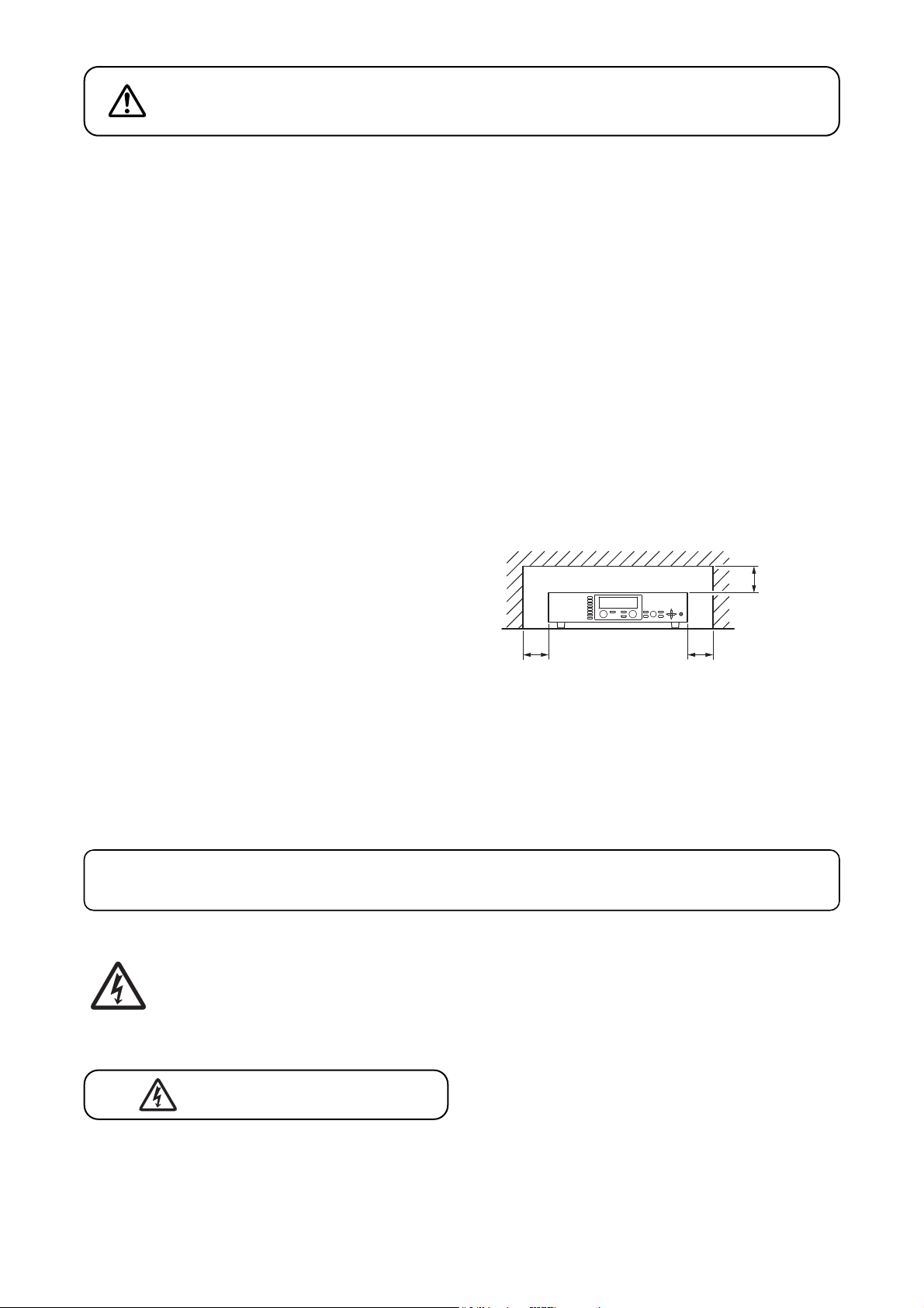
• Keep the 9000 series amplifier over 10 cm (3.94") away
objects that may obstruct air flow to prevent the unit's
from
internal temperature rise.
INPUT SELECT
1
2
3
4
OUTPUT VOLUME
INPUT VOLUME
5
ON/OFF
ON/OFF
6
OUTPUT SEL
7
8
POWER
PARAMETER
UTILITY
MEMORY
ESC/BACK
ENTER
Over 10 cm
(3.94”)
Over 10 cm (3.94”) Over 10 cm (3.94”)
When the Unit is in Use
• Do not operate the unit for an extended period of time with the sound distorting. This is an indication of a
malfunction, which in turn can cause heat to generate and result in a fire.
• Switch off the power, and unplug the power supply plug from the AC outlet for safety purposes when
cleaning or leaving the unit unused for 10 days or more. Doing otherwise may cause a fire or electric shock.
An all-pole mains switch with a contact separation of at least 3 mm in each pole shall be incorporated
in the electrical installation of the building.
The lighting flash with arrowhead symbol, within an equilateral triangle, is intended to alert the user
to the presence of uninsulated "dangerous voltage" within the product's enclosure that may be of
sufficient magnitude to constitute a risk of electric shock to persons.
ATTENTION
L'appareil ne doit pas être exposé aux éclaboussures ou écoulements et tous objets remplis de liquide, tels
que vases, ne doivent pas être sur l’appareil.
8
Page 9
3. GENERAL DESCRIPTION
TOA's 9000 series Amplifier is designed to be used in conjunction with optional modules and can be
configured for up to 8 inputs and 8 outputs. Usable modules include the following 9000 series plug-in
modules: D-001T and D-001R (2-channel input), T-001T (Audio output expansion), C-001T (Control I/O
expansion), ZP-001T (Zone paging), AN-001T (Ambient noise sensor), and RC-001T (Remote controller
interface), as well as 900 series input modules. The most appropriate modules can be selected depending on
applications.
The 9000 series amplifier can be used as a mixer that is appropriate for speech or sound reinforcement applications.
is equipped with signal processing and control functions, permitting all parameters to be set at the amplifier.
It
Each input can also be set as a paging input, to which one of 3 priority levels can be assigned.
The paging input takes precedence over other mixing inputs, thus allowing priority paging calls to go through
to the designated outputs. Paging calls can be activated by triggers of various types. Multiple paging calls can
be selectively used according to their priority levels. Thus, the 9000 series can effectively meet a room
combining application.
Setting data of both mixing and paging functions can be stored inside the amplifier.
The 9000 series come with power amplifier, can perform 2-channel or stereo broadcast in stand-alone operation.
All settings that can be made at the unit can also be made on the PC using the supplied dedicated software.
[Compatibility of the firmware version and software version]
This instruction manual supports the 9000 Series amplifiers' firmware Ver. 2.00 or later and the PC Setting
software Ver. 2.00 or later.
Some of the functions described in this manual do not work on the firmware and PC software versions earlier
than Ver. 2.00. If you use the older version of the 9000M2, update the firmware and PC software versions to
the latest ones. Also, be sure to back up the 9000M2's setting data using the PC Setting software before
performing updates.
Notes
• While performing version update, make sure to prevent the power cable and communication cable from
accidentally coming off.
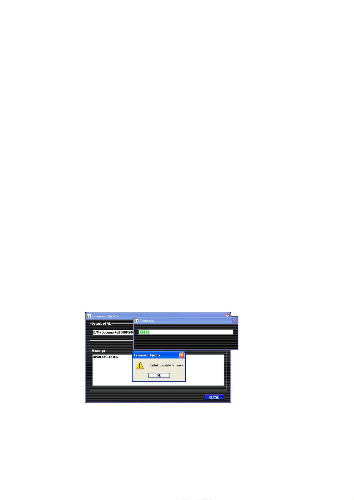
• Once updated to firmware Ver. 2.00 or later, you cannot downgrade back to firmware Ver. 2.00 or earlier.
The indication "INVALID VERSION" is displayed on the 9000 amplifier's front-mounted display (VFD) and
PC's screen when attempting to perform downgrade. (Refer to the screen shot below.)
The indication is displayed for a few seconds, then the 9000 amplifier restarts with the version remaining
unchanged.
9
Page 10

4. FEATURES
• Can be configured as a mixer or paging amplifier by settings, depending on application.
• Eight module slots enable audio input and output configuration ranging from 1 input and 1 output to 8 inputs
and 8 outputs.
• All settings can be performed at the unit using the built-in vacuum fluorescent display (VFD), setting keys
and Parameter setting knob on the front panel.
• Paging calls can be made from the designated outputs by setting the paging source, priority, and trigger
even while the unit is being used as a mixer.
• Up to 32 mixing settings can be stored as Scene memory, which can be recalled by the unit or external
connected equipment.
• Different paging calls can be selectively used depending on situations as two or more paging sources can be
set and different priority levels can be assigned to them. Other functions allow paging calls to be activated
with various types of triggers and up to 32 paging groups to be saved independently of scene memory.
• An RS-232C port permits remote control of the unit using an AMX*
external equipment.
• With the use of the optional AN-001T Ambient Noise Sensor Input module and AN-9001 Ceiling Mount
Microphone, the amplifier's output volume can be automatically adjusted in response to the change in
ambient noise level.
• Using the optional RC-001T Remote Control Module in conjunction with the Remote control panels such as
ZM-9011, ZM-9012, ZM-9013, or ZM-9014 permits operations including scene and sound source switchings,
paging initiation, control output ON/OFF, and volume adjustment to be remotely controlled.
1
or Crestron*2controller, or similar
• The optional ZM-9001 Zone Manager adds 6 control inputs, while the optional ZM-9002 Zone Manager adds
4 control inputs and 1 volume control.
• A ducker function*
3
permits paging calls to be made without interrupting BGM broadcasts. Besides, an auto-
mixing function (ducker function*3and NOM attenuation function*4) automatically adjusts the output gain.
*1AMX is a trademark of AMX Corporation.
2
Crestron is a trademark of Crestron Electronics, Inc.
*
*3The Ducker function automatically attenuates input signals with lower priority when two or more audio
signals are simultaneously received.
4
The NOM (Number of Open Microphones) attenuation function automatically adjusts the output channel
*
gain depending on the number of open microphones.
10
Page 11
5. INSTALLATION PRECAUTIONS
s'tinu
internal temperature rise.
Over 10 cm (3.94”)
INPUT SELECT
1
2
3
4
INPUT VOLUME
5
ON/OFF
6
7
8
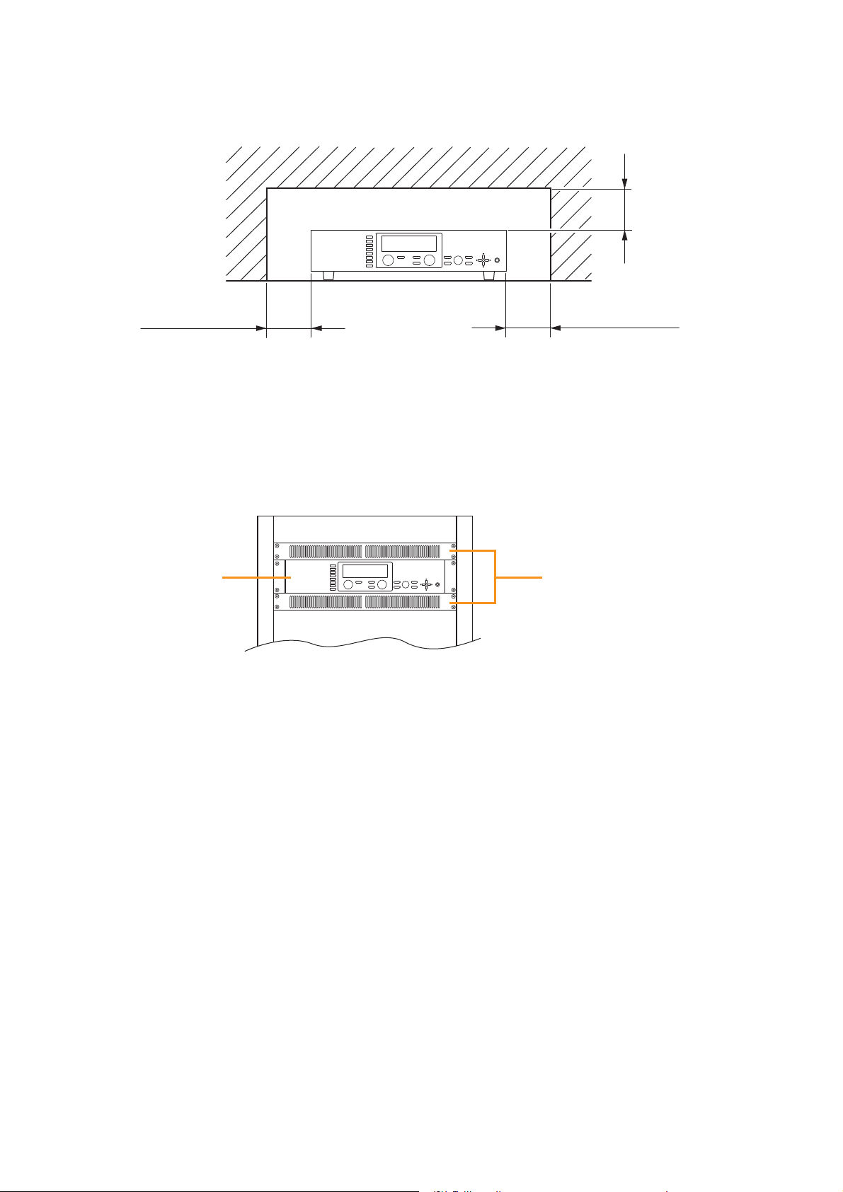
• When mounting the unit on an equipment rack
· Use the supplied rack-mounting bracket. (For the bracket attachment, refer to p. 121 "RACK MOUNTING
BRACKET ATTACHMENT.")
· Have the unit well-ventilated, and be sure to mount a 1U or more size perforated panel above and below
the unit to prevent the unit's internal temperature rise.
PARAMETER
OUTPUT VOLUME
MEMORY
ON/OFF
ENTER
OUTPUT SEL
POWER
UTILITY
ESC/BACK
Over 10 cm (3.94”)Over 10 cm (3.94”)
ehttneverpotwolfriatcurtsboyamtahtstcejbomorfyawa)"49.3(mc01revo9000 series amplifierehtpeeK•
INPUT SELECT
1
2
3
CP-9500M2-EB
or A-9500D2-AS 1CE
4
5
6
7
8
INPUT VOLUME
OUTPUT VOLUME
ON/OFF
ON/OFF
OUTPUT SEL
POWER
PARAMETER
UTILITY
MEMORY
ESC/BACK
ENTER
Perforated panels
6. HANDLING PRECAUTIONS
• The supplied power supply cord is designed for exclusive use with this unit. Never use it with other
equipment.
• Use the unit in locations where the temperature is between –10 and +40°C or 14 and 104°F (no
condensation should be formed), and the humidity is less than 80%.
• The unit is a precision audio component. To prevent failure, avoid locations where it may be exposed to
strong shocks or vibrations.
• To clean, be sure to first disconnect the power supply plug from the AC outlet, then wipe with a dry cloth.
When extremely dirty, use a soft cloth dampened in neutral detergent. Never use benzene, thinner, alcohol
or chemically-treated towels, which may damage the unit's finish.
11
Page 12
7. NOMENCLATURE AND FUNCTIONS(EXAMPLE FOR CP-9500M2-EB)
7.1.CP-9500M2-EB Amplifier
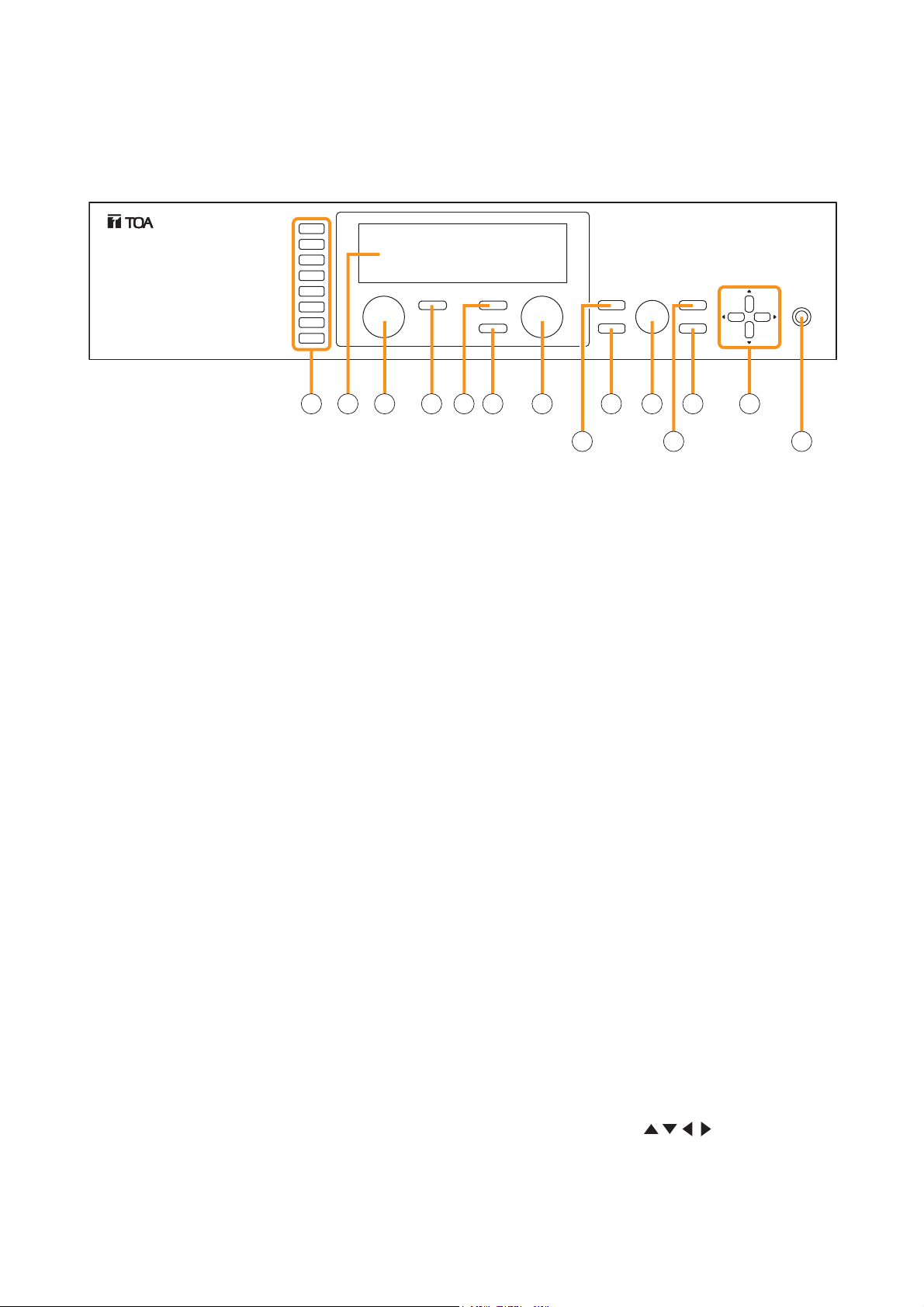
[Front]
INPUT SELECT
1
2
3
4
5
6
7
8
INPUT VOLUME
ON/OFF
ON/OFF
OUTPUT SEL
OUTPUT VOLUME
MEMORY
ENTER
PARAMETER
UTILITY
ESC/BACK
POWER
2 3 4 5 6 7 8
1. Power switch and Power indicator
Press this switch to turn on the power. The power
indicator lights. To turn off the power, hold down
the switch for at least 0.5 second.
Note
The power switch is a soft-switch, so the internal
microcomputer is still operating even when the
power switch is set to OFF.
2. Input channel selection keys
Select the input channel for which the volume is
adjusted or parameter is set.
Pressing the key causes the corresponding red
channel indicator to light on the vacuum
fluorescent display (VFD).
3. Vacuum fluorescent display (VFD)
Displays the setting screen, input and output
selection status, channel ON/OFF status, input and
output level meter indication, and fader position.
The VFD enters the display saver mode if no key is
operated for a fixed period of time.
(Refer to p. 13 "VFD on-screen indications.")
4. Input volume control
Adjusts the gain of the input channel selected with
the input channel selection key (2).
5. Input channel ON/OFF key
Turns on or off the channel selected with the input
channel selection key (2).
10 111213 14
9
7. Output channel selection key
Selects the output channel for which the volume
is adjusted or parameter is set. The output
channel indicators on the VFD light in sequence
each time the key is pressed.
8. Output volume control
Adjusts the gain of the output channel selected
with the output channel selection key (7).
9. Memory key
Used to save the current settings into a Scene
memory or recall a saved Scene setting.
10. Enter key
Press this key when "OK ?" is displayed in the
setting screen or when proceeding to the next
screen.
11. Parameter setting knob
Rotate this knob to select the setting item or
setting contents.
12. Utility menu key
Used to perform Utility setting.
13. Escape/Back key
Used to revert back to a previous screen when
advanced with the Enter key during setting
operation, or return to the screen on the upper
hierarchy level.
1
6. Output channel ON/OFF key
Turns on or off the channel selected with the
output channel selection key (7).
14. Screen shift keys [ ]
Move the setting screen or setting item.
12
Page 13
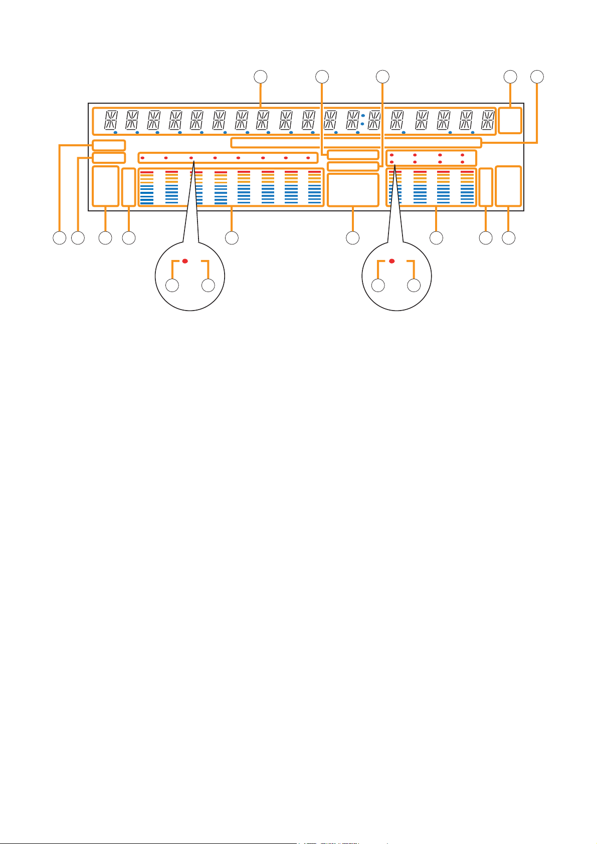
[VFD on-screen indications]
15 16 18 1917
COM
FAULT
FADER
LEVEL
12 345678
OL
0
–10
–20
–30
–40
GAIN d B FREQQ
KEYLOCK
EMERGENCY
GATE
TONE
DUCK
LOUD
EQ
NOM
COMP
DELAY
12 34
56 78
21 22 2320 2726 30 31 32
5533
28 2924 25
–10
–20
–30
–40
OL
0
d B
kHz
m sec
FADER
LEVEL
15. 14-Segment,18-digit alphanumeric display
Displays the corresponding setting screen or
data when each function key is pressed.
Parameters being edited flash.
16. Keylock indicator
Lights when the key lock function is enabled, and
flashes while the key lock function is being
edited.
17. Emergency indicator
Lights when the control input set for "Emergency
mute" becomes active.
18. Unit indicator
Displays the unit of each parameter when it is set.
19. GAIN, dB, Q, FREQ indicators
Lights when the equalizer is adjusted.
20. COM indicator
Remains lit during communications via the RS232C interface.
21. Fault indicator
Lights or flashes when the unit's failure or other
abnormal conditions are detected.
(Refer to p. 132 "ERROR INDICATIONS.")
22. Input meter status indicator
Indicates which the input level (LEVEL) or input
fader position (FADER) is being displayed on the
input meter (26).
Note
Input level is displayed only when the D-001T/R
module is used.
23. Input level indication
Scale of levels (in dB) for the input meter.
24. Input channel selection indicator (red dot)
Lights when the corresponding input channel is
selected, and flashes while parameters are being
edited.
25. Input channel ON/OFF indicator
(channel number)
The indicators for all channels normally light
regardless of whether or not the channels can be
selected by the input channel selection keys (2)
or can be used (p. 134 "Remarks"), while they
flash when turned off by the input channel
ON/OFF key (5).
The indicators of unused channels can be set to
be off in the Utility setting item.
26. Input meter
Indicates the signal level or input fader position
of each input channel.
Which the meter is indicating is displayed on the
input meter status indicator (22).
Notes
• The input meter is kept on even for the channel
that is turned off or muted.
• Input level is displayed only when the
D-001T/R module is used.
27. Effect indicator
Lights when effect is on, and flashes while the
parameters are being edited.
13
Page 14

28. Output channel selection indicator (red dot)
Lights when the corresponding output channel is
selected, and flashes while parameters are being
edited.
29. Output channel ON/OFF indicator
(channel number)
Lights when the corresponding output is on (i.e.
in operation mode), and flashes when off.
The number of channels of which indicators light
depends on the modules used.
30. Output meter
Indicates the signal level or output fader position
of each output channel. Which the meter is
indicating is displayed on the output meter status
indicator (32).
Notes
• Even when the 9000 series's output channel 1
or 2 is turned off or muted, the output meter for
these channels remains on.
• The output meters are not influenced by their
output volume control settings.
31. Output level indication
Scale of levels (in dB) for the output meter.
32. Output meter status indicator
Indicates which the output level (LEVEL) or
output fader position (FADER) is being displayed
on the output meter (30).
Notes
• The VFD automatically enters the display saver mode and indicates “DISPLAY SAVER MODE. PRESS
ANY KEY” scrolling sideways if no key is operated for 20 minutes. In this case, the VFD reverts to normal if
any key is pressed. Be sure to press any key to make the VFD active before performing any operation.
• The VFD is a consumable item. Its brightness decreases by half after about 30000 hours of continuous
lighting.
A built-in display saver mode that automatically dims the VFD light will extend the life of VFD.
14
Page 15
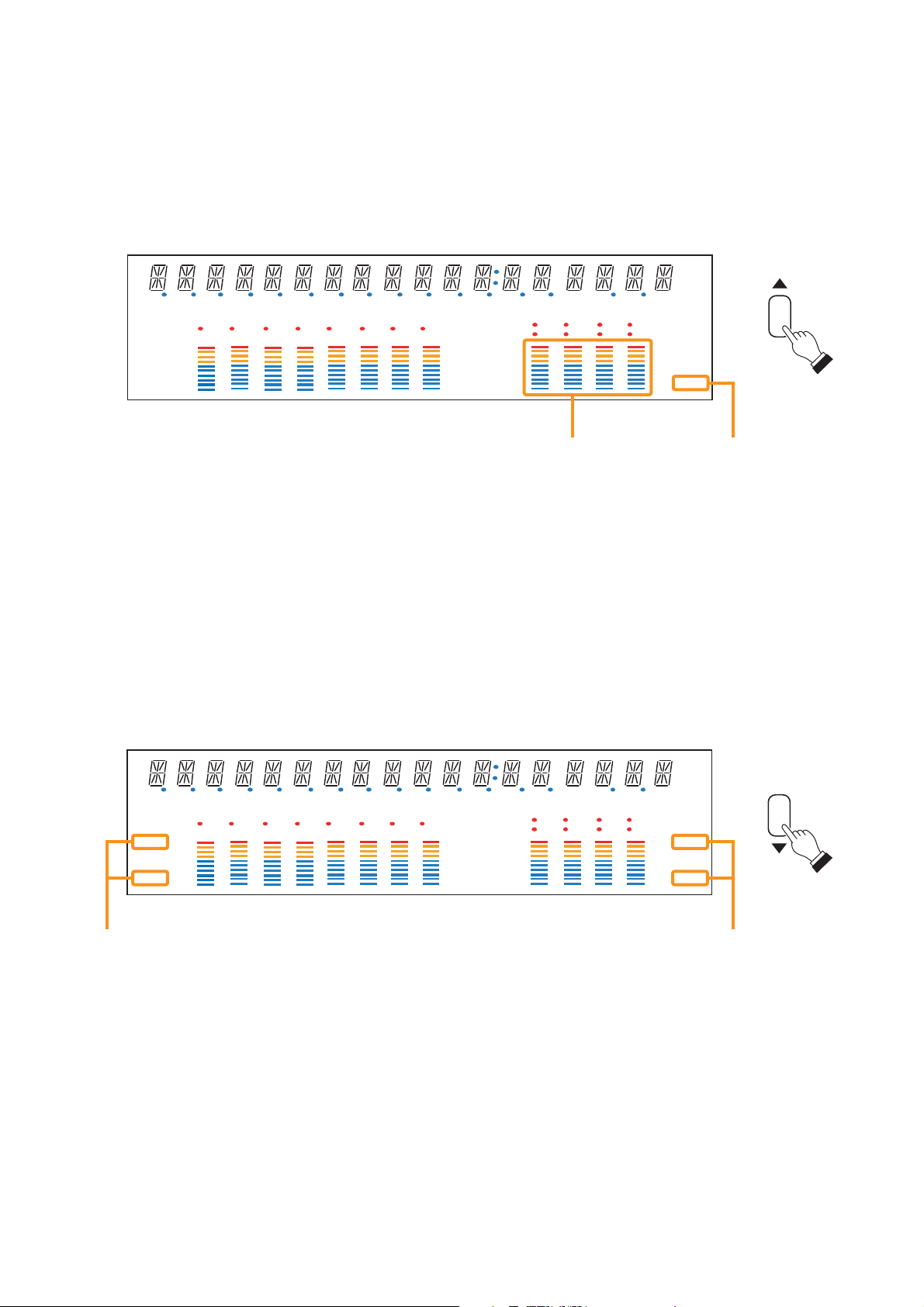
[Changing the indicated channels on the LEVEL output meter]
The output meter indicates the signal levels of only a set of 4 channels: CH 1 – 4 (factory-preset) or CH 5 – 8.
When the input or output gain setting screen is displayed, pressing the Up shift key alternately switches the
level indication between CH 1 – 4 and CH 5 – 8.
The LEVEL indicator of the output meter status indicator flashes while the CH 5 – 8 are indicated, and stays lit
while the CH 1 – 4 are indicated.
In the same manner, the output meter also changes in the Fader indication.
d B
kHz
msec
COM
FAULT
FADER
LEVEL
12 345 678
OL
0
–10
–20
–30
–40
GAIN d B FREQQ
KEYLOCK
EMERGENCY
GATE
TONE
DUCK
LOUD
NOM
EQ
COMP
DELAY
12 34
56 78
FADER
OL
0
–10
–20
–30
LEVEL
–40
Output meters Output meter status indicator
[Changing the input and output meter display status]
When the input or output gain setting screen is displayed, pressing the Down shift key alternately switches the
input and output meter display status between the signal level and the fader position.
The LEVEL indicators on both input and output meters light when the signal levels are indicated, while the
FADER indicators light when the fader positions are indicated.
When an input channel's gain setting screen is displayed, the meter display status can be switched between
the signal level and fader position each time the input channel selection key of the channel being set is
pressed.
d B
kHz
msec
COM
FAULT
FADER
LEVEL
12 345 678
OL
0
–10
–20
–30
–40
Input meter status indicators Output meter status indicators
GAIN d B FREQQ
KEYLOCK
EMERGENCY
GATE
TONE
DUCK
LOUD
EQ
NOM
COMP
DELAY
12 34
56 78
FADER
OL
0
–10
–20
–30
LEVEL
–40
Note: The figure above is the VFD screen display when the input and output levels are indicated.
15
Page 16
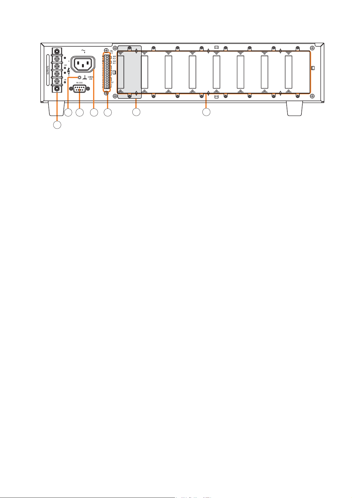
[Rear]
9000 Series Power Amplifier CP-9500M2-EB
100V/20
500W
100V/20
500W
2
220-240V 50/60Hz
220
34
36
35 38
39 40
37
34. Functional earth terminal
Hum noise may be generated when external
equipment is connected to the unit. Connecting
this terminal to the functional earth terminal of
the external equipment may reduce the hum
noise.
Note: This terminal is not for protective earth.
35. AC inlet
Connect the supplied power cord.
36. RS-232C serial communication port
Connector for communications with a personal
computer or control equipment.
37. Speaker output terminal
Connect speakers of which total impedance
matches the amplifier's output impedance.
(Refer to p.112 "Speaker Output Terminal
Connections.")
38. Control-I/O connection terminal
Connect a 10 kΩ (linear taper) variable resistor
or input the DC voltage of 0 to +10 V to the
remote volume control terminals (REMT VOL 1
and 2) when remotely adjusting the volume.
To perform other remote control operation,
connect the ZM-9001 or ZM-9002 Zone
Manager.
Input and output terminals (IN and OUT) are
used to change the unit's internal status or output
internal status data to external equipment after
having received various control signals.
39. Blank panel (accessory)
Attach the blank panels to open slots.
40. Module slots
900 Series or 9000 Series modules can be
inserted into these slots.
(Refer to p. 106 "MODULE INSTALLATION.")
16
Page 17
7.2. Optional Modules
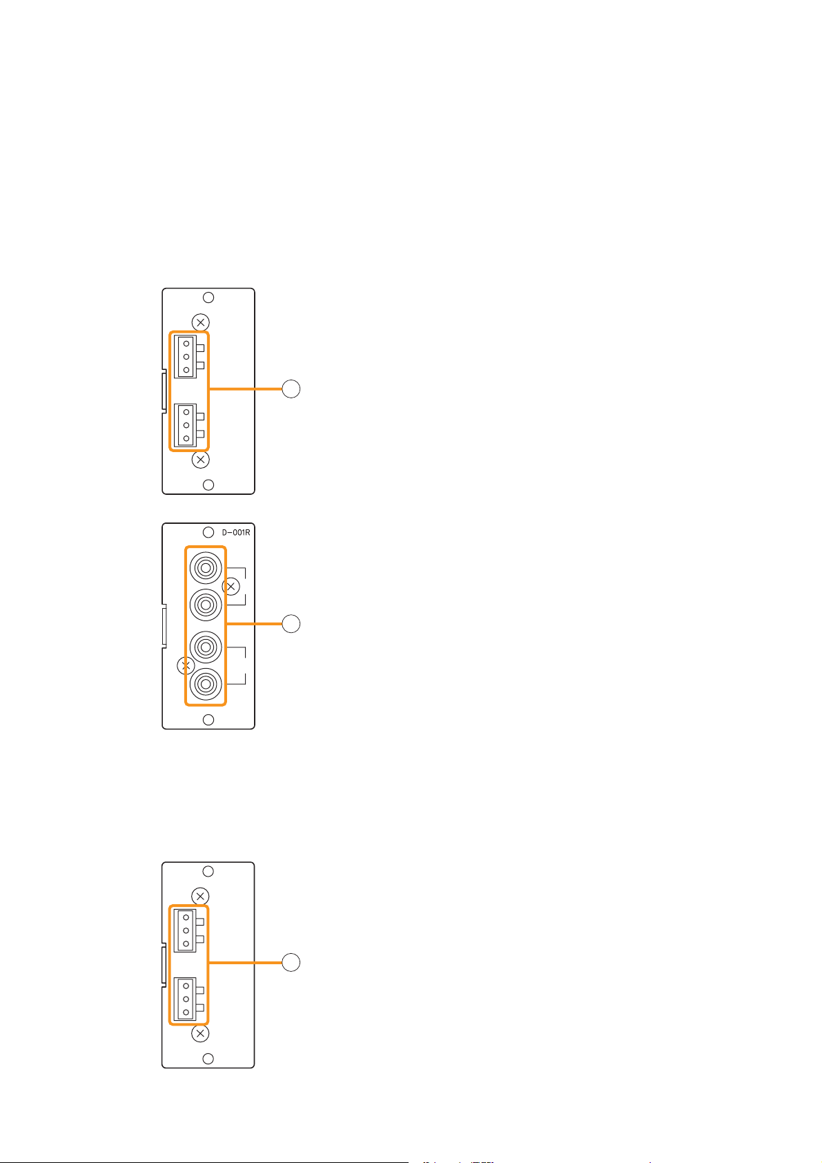
7.2.1. D-001T and D-001R (2-Channel Input Modules)
The D-001T and D-001R modules are designed for use with the 9000 series.
Up to 4 modules (8 channels in total) can be inserted into the amplifier.
Both modules can handle signals ranging from microphone level (–60 dB) to line level (–10 dB) in 9 input
sensitivity levels. They have an internal digital signal processor that can process input signals.
The D-001T can supply phantom power (24 V).
The D-001T or D-001R is required to use a VOX (Voice Operated Exchange) function and input channel level
meter.
[D-001T]
[D-001R]
D-001T
1
Hot
Cold
Earth
2
Hot
Cold
Earth
[D-001T]
1. Monaural input terminals [1, 2]
Electronically-balanced input terminals.
Type of connector: 3P removable terminal blocks
1
Input level: –60 dB to –10 dB selectable
Input impedance: 10 kΩ when the phantom power is OFF,
and 3 kΩ when ON
[D-001R]
1. Monaural input terminals [1, 2]
1
Unbalanced input terminals.
Type of connector: RCA jacks
1
Input level: –60 dB to –10 dB selectable
Input impedance: 10 kΩ
2
Two inputs of each channel are mixed.
7.2.2. T-001T (Audio Output Expansion Module)
The T-001T module is designed for use with the 9000 serise and can expand 2 output channels per module.
Since the main unit has 2 fixed outputs, the audio output can be expanded to 8 channels by using a maximum
of 3 modules (6 channels).
T-001T
2. Monaural output terminals [1, 2]
Electronically-balanced 3P removable terminal blocks.
Hot
Cold
Earth
Hot
Cold
Earth
1
2
2
Output level: 0 dB
Output impedance: 600 Ω
For unbalanced connection, connect the unit's Hot and Earth
terminals to the connected equipment's Signal and GND
terminals, respectively. (Keep the unit's Cold terminal free.)
17
Page 18
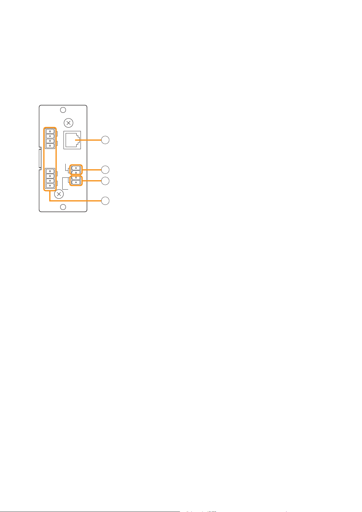
7.2.3. ZP-001T (Zone Paging Module)
The ZP-001T module is designed for use with the 9000 series and functions as an interface to connect the
9000 series to an analog PABX, allowing zone paging to be initiated from the PABX. Only one ZP-001T
module can be used per 9000 series.
There are two operation modes: Ring signal and Paging port modes. Select one of the two modes when using
this module.
The operation method differs depending on the set operation mode. (Refer to p. 46 "Making Zone Paging.")
ZP-001T
3. Telephone input terminal [TEL IN] (Modular jack)
Interface connector for an analog PABX.
CTRL
OUT
CTRL
OUT
1
G
2
G
TEL IN
PAGING IN
3
G
4
G
G
CONTACT
IN
3
4
5
6
Connect a PABX to this terminal when using the module in the ring
signal mode.
4. Paging input terminal [PAGING IN]
4-pin removable terminal block, 2 pins are used for this input.
This terminal is used to connect a PABX in the paging port mode.
5. Control input terminal [CONTACT IN]
4-pin removable terminal block, 2 pins are used for this input.
Connect the control output from a PABX to this terminal.
6. Control output terminals [CTRL OUT 1 G, 2 G, 3 G, 4 G]
4-pin removable terminal blocks, control output terminals.
Note: These terminals are not used in the 9000 series amplifier.
[Requirements of the PABX to be connected to the ZP-001T]
• The PABX shall be complaint with TIA/EIA-464-B standard.
• Specifications or conditions required in each of the following modes shall be satisfied:
Note: The ZP-001T may malfunction if the connected PABX does not meet the above requirements.
(A) When using the module in the Paging port mode
• Connection: Line level paging port
• Signaling method: DTMF (The module cannot be operated with dial pulse.)
• Shall provide no-voltage make contact during paging calls.
• Insensitive to whether loop voltage exists or not, and whether polarity of the loop voltage is reversed or
not when a line connection is established.
Note
If the PABX does not meet the above requirements, use the D-001T/R module and set the trigger to
"VOX" (Voice Operated Exchange) to initiate paging. In this case, the paging output channel cannot be
selected, which differs from the operation by the ZP-001T.
(B) When using the module in the Ring signal mode
• Connection: Analog two-wire extension line, loop start
• Signaling method: DTMF (The module cannot be operated with dial pulse.)
• Reorder tone: 120 IPM (impulses per minute) or less
• Loop voltage: 24 V DC or more (polarity insensitive), which should be supplied from the PABX.
• Insensitive to whether polarity of the loop voltage is reversed or not at a call from the PABX.*
• Loop voltage supply shall not be cut off from the beginning of a call to the reorder tone out.*
• The state of CPC (Calling Party Controlled) break or "Open Loop Disconnect" shall be reset at the
PABX.*
* Note that there is no need to meet these requirements provided that the ZP-001T's control input terminals
are kept closed. However, noise may be output if the line is physically disconnected during a paging call
because the ZP-001T cannot recognize the line cutoff nor stop output for 30 seconds after paging initiation.
18
Page 19
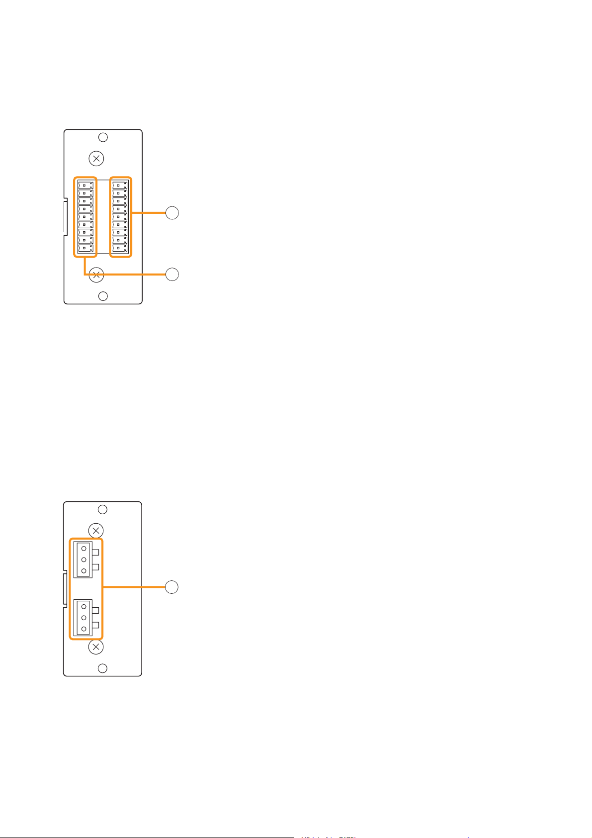
7.2.4. C-001T (Control I/O Expansion Module)
The C-001T module is designed for use with the 9000 series and can provide up to 8 channels each of input
and output expansion.
Since the main unit has 4 fixed inputs and outputs each, the control input and output can be expanded to up to
12 channels each when the C-001T module is used.
C-001T
7. Control input terminal [IN 1, 2, 3, 4, 5, 6, 7, 8, E]
9-pin removable terminal block, 8-circuit control input terminal.
Individual input functions are assigned on the front panel setting screen
OUT IN
1
2
3
4
5
6
7
8
E
7
of the main unit.
8. Control output terminal [OUT 1, 2, 3, 4, 5, 6, 7, 8, E]
9-pin removable terminal block, 8-circuit control output terminal.
Individual output functions are assigned on the front panel setting screen
of the main unit.
8
7.2.5. AN-001T (Ambient Noise Sensor Input Module)
The AN-001T module is designed for use with the 9000 series and automatically adjusts the amplifier's output
volume in response to the change in ambient noise level.
Maximum 2 AN-001T modules (4 channels in total) can be used per 9000 series.
It can handle signals from microphone level (–60 dB) to line level (–10 dB) by controlling the gain in 9 steps.
Phantom power (+24 V) can be supplied to a condenser microphone.
The AN-001T's inputs are for detecting ambient noise level and cannot be used as normal audio inputs.
Ambient noise fed to the inputs can be monitored when the monitor function is set to ON in the Input setting
flow.
AN-001T
1
Hot
Cold
Earth
2
Hot
Cold
Earth
9. Monaural input terminals [1, 2]
Electronically-balanced 3P removable terminal blocks.
Input level: –60 dB to –10 dB selectable.
Input impedance is 10 kΩ when the phantom power is OFF, and 3 kΩ
when ON.
9
19
Page 20

7.2.6. RC-001T (Remote Control Module)
The RC-001T is an interface module to connect between the 9000 series and the ZM-9011, ZM-9012,
ZM-9013, or ZM-9014 Remote Control Panel of data communication type. It allows the control panels to
perform paging activation, scene memory change, and input/output volume control.
Up to 16 control panels can be connected to the RC-001T.
Power for the connected control panels is supplied from the AC adapters connected to the RC-001T. One AC
adapter is needed every 8 control panels.
The maximum communication cable length between the RC-001T and control panels is max. 800 m (875 yd)
in total.
10. Data line connection terminals for Link A
Connect the communication line from up to 8 control panels.
Note that the communication line has polarities.
10
11
12
13
14
15
11. 24 V DC output terminals for Link A
Supply 24 V DC power to the control panels.
12. Data line connection terminals for Link B
Connect the communication line from up to 8 control panels.
Note that the communication line has polarities.
13. 24 V DC output terminals for Link B
Supply 24 V DC power to the control panels.
14. AC adapter input terminal for Link A
Connects the AC adapter for supplying DC power to the
control panels of LINK A.
15. AC adapter input terminal for Link B
Connects the AC adapter for supplying DC power to the
control panels of LINK B.
20
Page 21
7.3. Optional Accessories
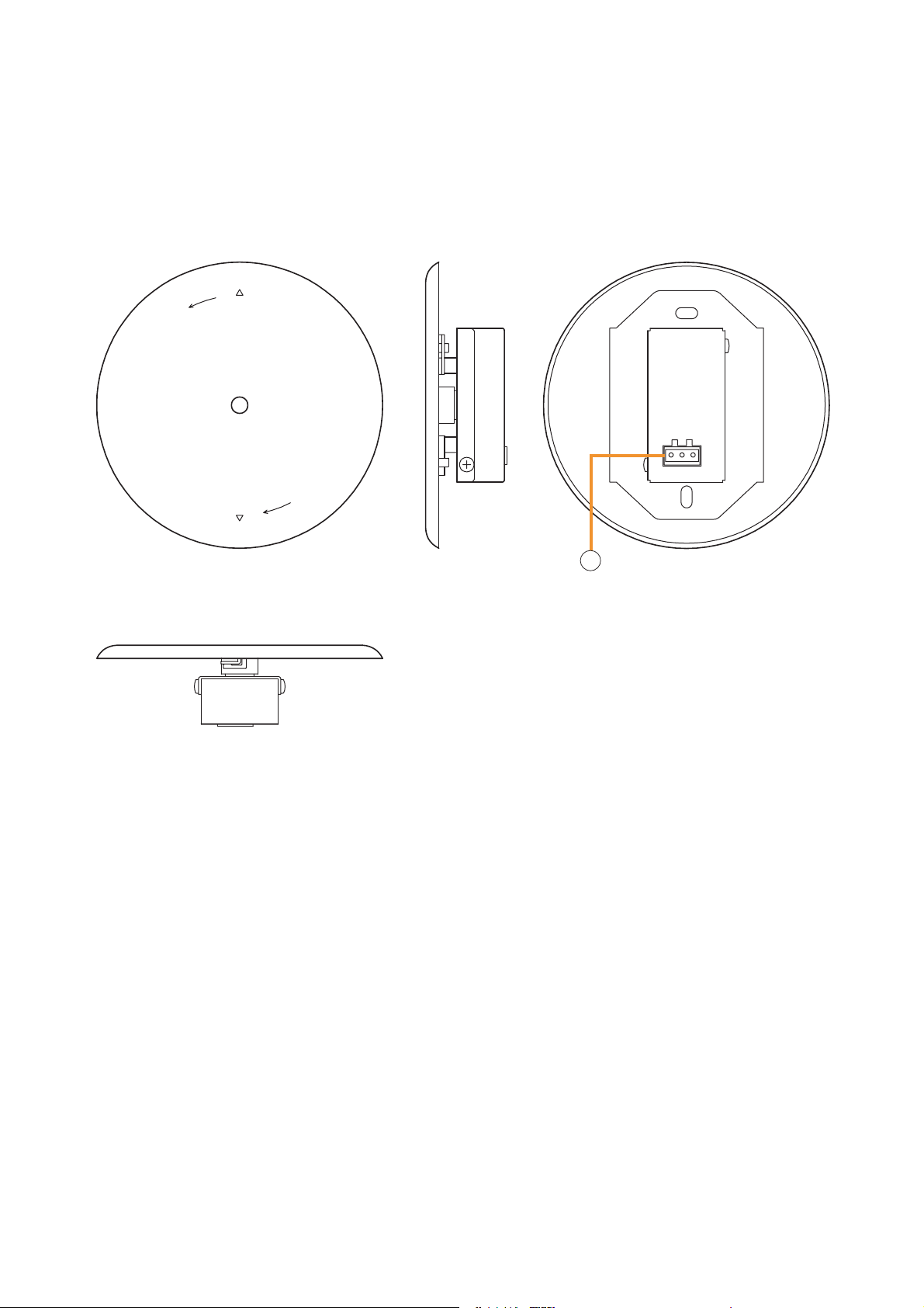
7.3.1. AN-9001 (Ceiling Mount Microphone)
The AN-9001 is designed to be mounted in a wall or ceiling with the use of a 1-gang electrical box.
It is used in conjunction with the AN-001T Ambient Noise Sensor Input module in the 9000 series.
[Front]
[Bottom]
Release
Lock
[Side] [Rear]
1
Hot
Cold
Earth
1. Microphone output terminal [Hot, Cold, Earth]
Electronically-balanced 3P removable terminal block.
Sensitivity: –5 dB (1 kHz, 0 dB=1 V/Pa)
Output impedance: 200 Ω
Note
In designing the layout of the AN-9001, pay particular attention to the following points so that the AN-9001 and
AN-001T in combination can function effectively.
• Position the AN-9001 fully away from the speaker to be used for zone announcement. Doing otherwise may
cause the AN-9001 to detect the speaker sound as noise, failing to keep the optimum sound level.
• Do not position the AN-9001 near the equipment that constantly generates loud noise. If positioned, the AN9001 will respond to such loud noise, failing to respond to the change in ambient noise level.
21
Page 22
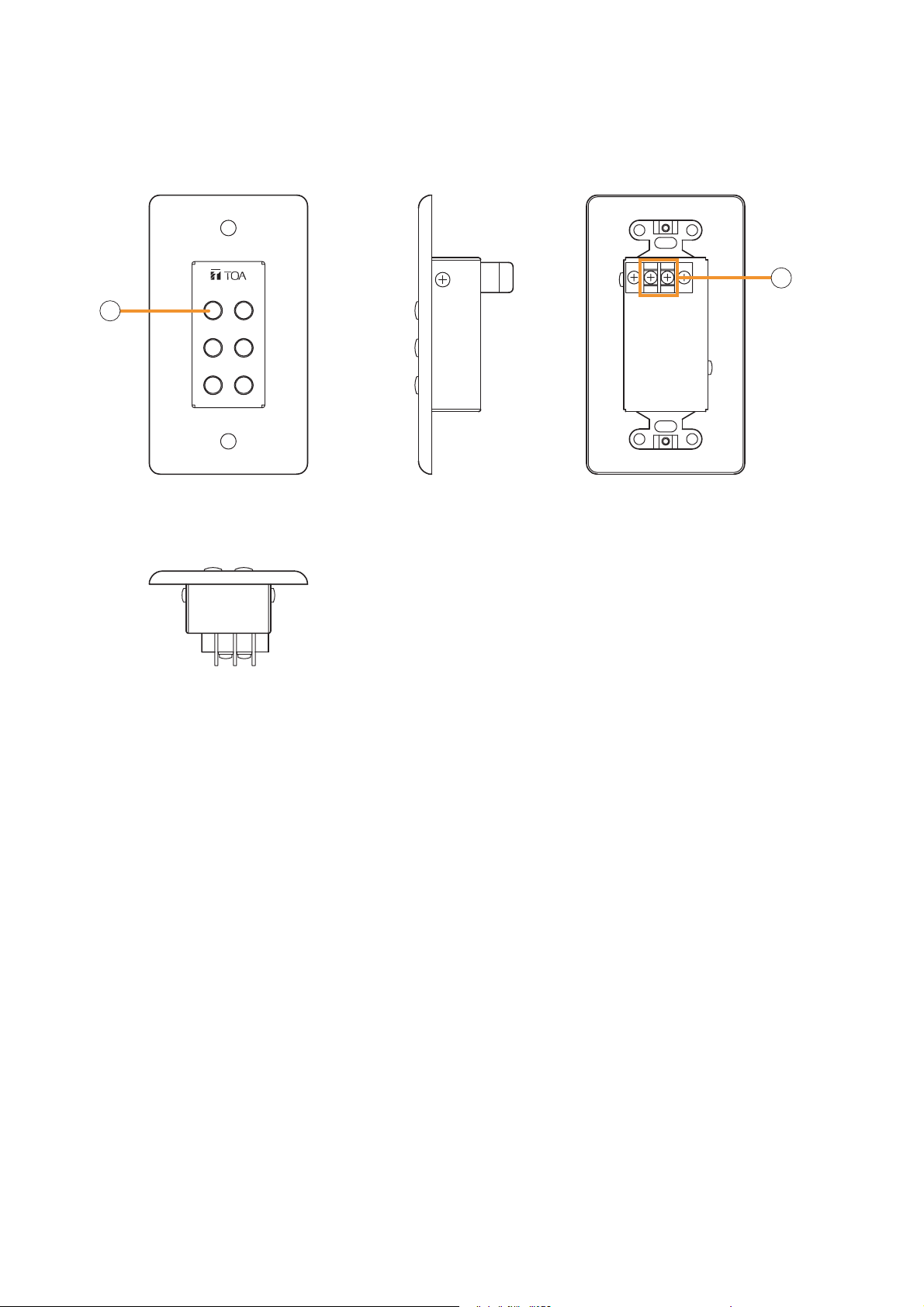
7.3.2. ZM-9001 (Zone Manager)
The ZM-9001 adds 6 control inputs and can be mounted in a 1-gang electrical box.
[Front] [Rear][Side]
2
[Bottom]
1
2
3
4
6
5
E OUT
3
2. Control buttons [1 – 6]
Activate the function assigned to them when pressed.
3. Control output terminal [E, OUT]
Connect this terminal to the 9000 series REMT VOL terminal.
Use a shielded cable with 50 Ω or less line resistance (per line) for this connection.
Avoid installation of this cable and power cables in the same conduit. Separate piping.
22
Page 23
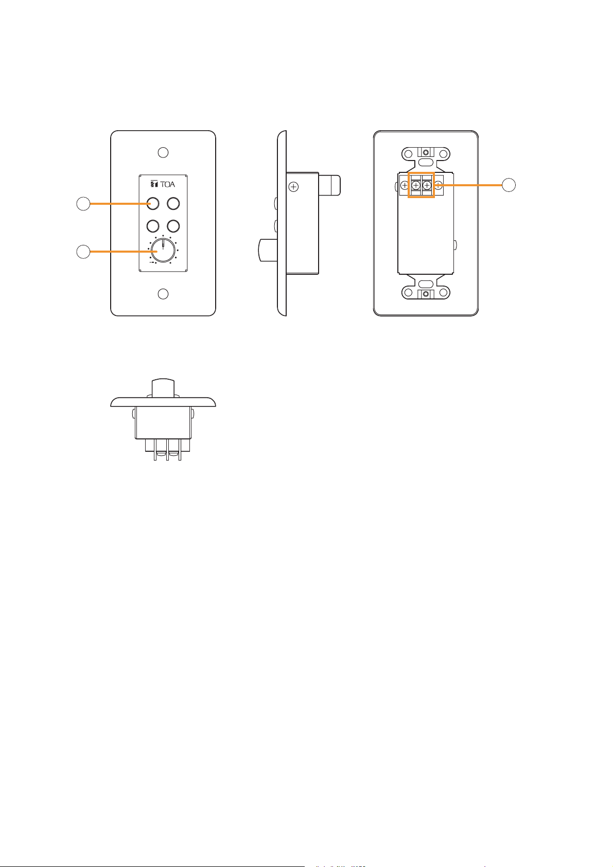
7.3.3. ZM-9002 (Zone Manager)
The ZM-9002 adds 4 control inputs and 1 volume control, and can be mounted in a 1-gang electrical box.
[Front] [Rear][Side]
4
5
[Bottom]
132
6
E OUT
4
0
4. Control buttons [1 – 4]
Activate the function assigned to them when pressed.
5. Volume control
Adjusts the volume on the assigned input or output channel.
6. Control output terminal [E, OUT]
Connect this terminal to the 9000 series REMT VOL terminal.
Use a shielded cable with 50 Ω or less line resistance (per line) for this connection.
Avoid installation of this cable and power cables in the same conduit. Separate piping.
23
Page 24
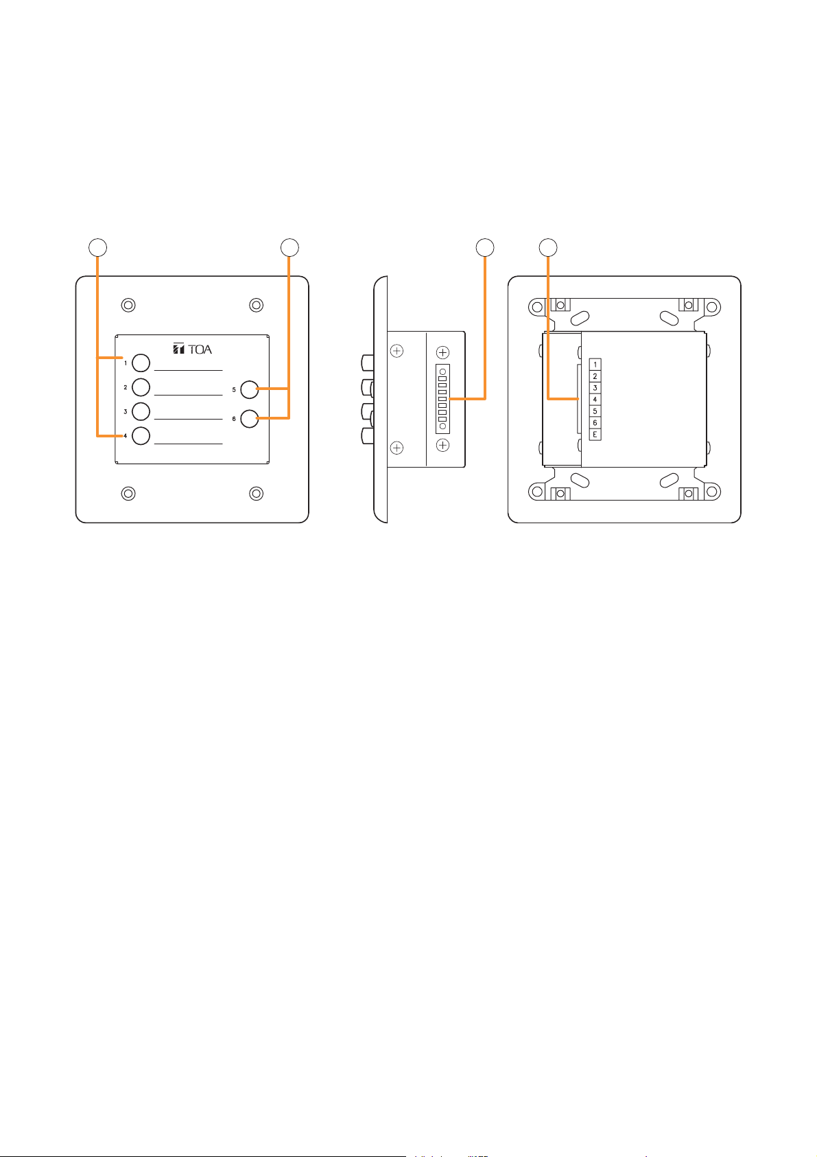
7.3.4. ZM-9003 (Zone Manager)
The ZM-9003 is a remote control switch panel with 4 control selection buttons and 2 control buttons.
Connecting it to the 9000 series's control input terminal permits various controls such as BGM source selection
and the sound volume adjustment.
It can be mounted in an American standard 2-gang electrical box in a wall.
[Front] [Side] [Rear]
7 8 9 9
7. Control selection buttons (Interlocking selection switches) [1 – 4]
Activate the function assigned to them when pressed.
8. Control buttons (Momentary switches) [5, 6]
Activate the function assigned to them when pressed.
9. Control output terminal [1 – 6, E]
Connect this terminal to the 9000 series's control input terminal.
Use a cable with 250 Ω or less line resistance (per line) for this connection.
Avoid installation of this cable and power cables in the same conduit. Separate piping.
24
Page 25
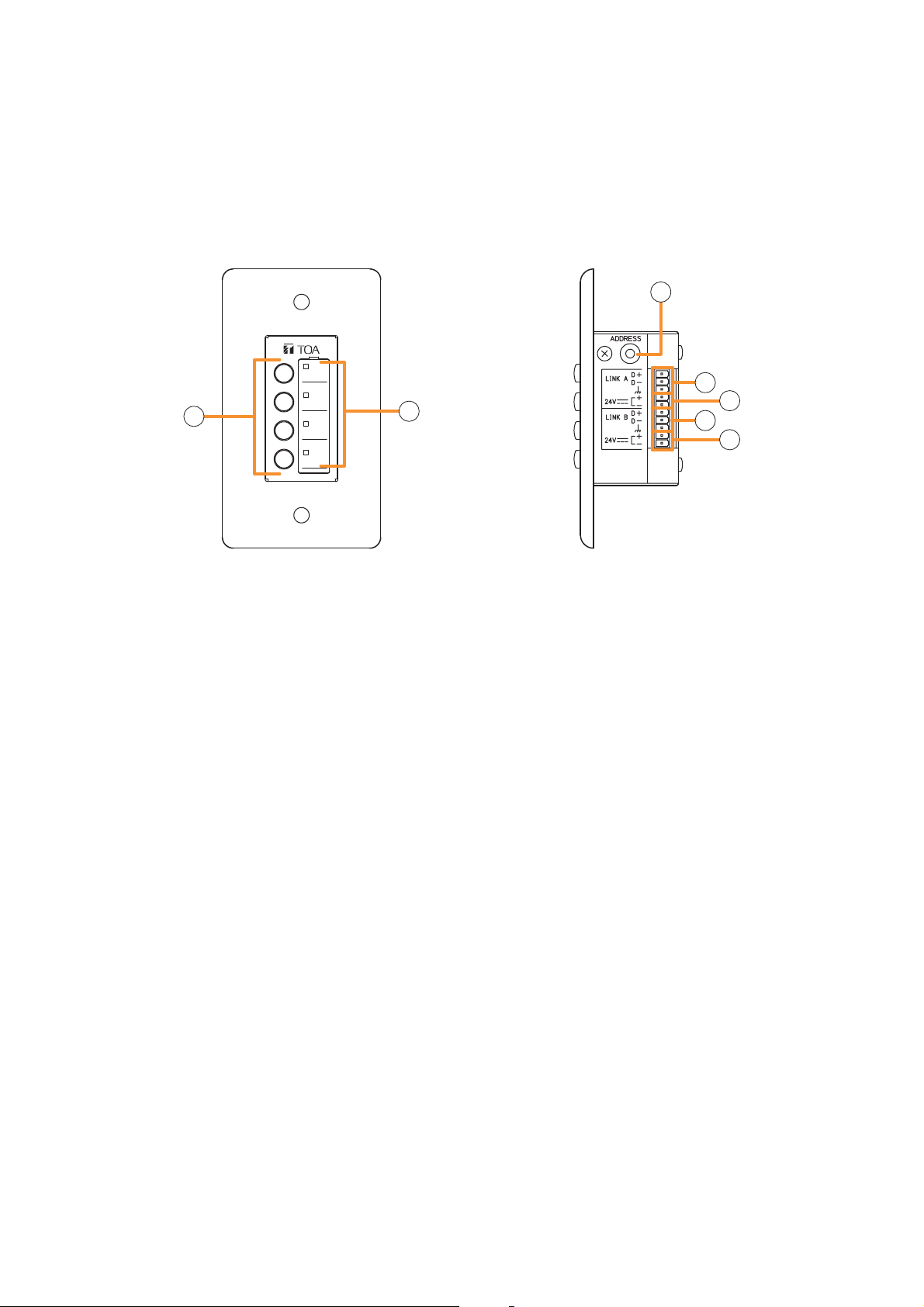
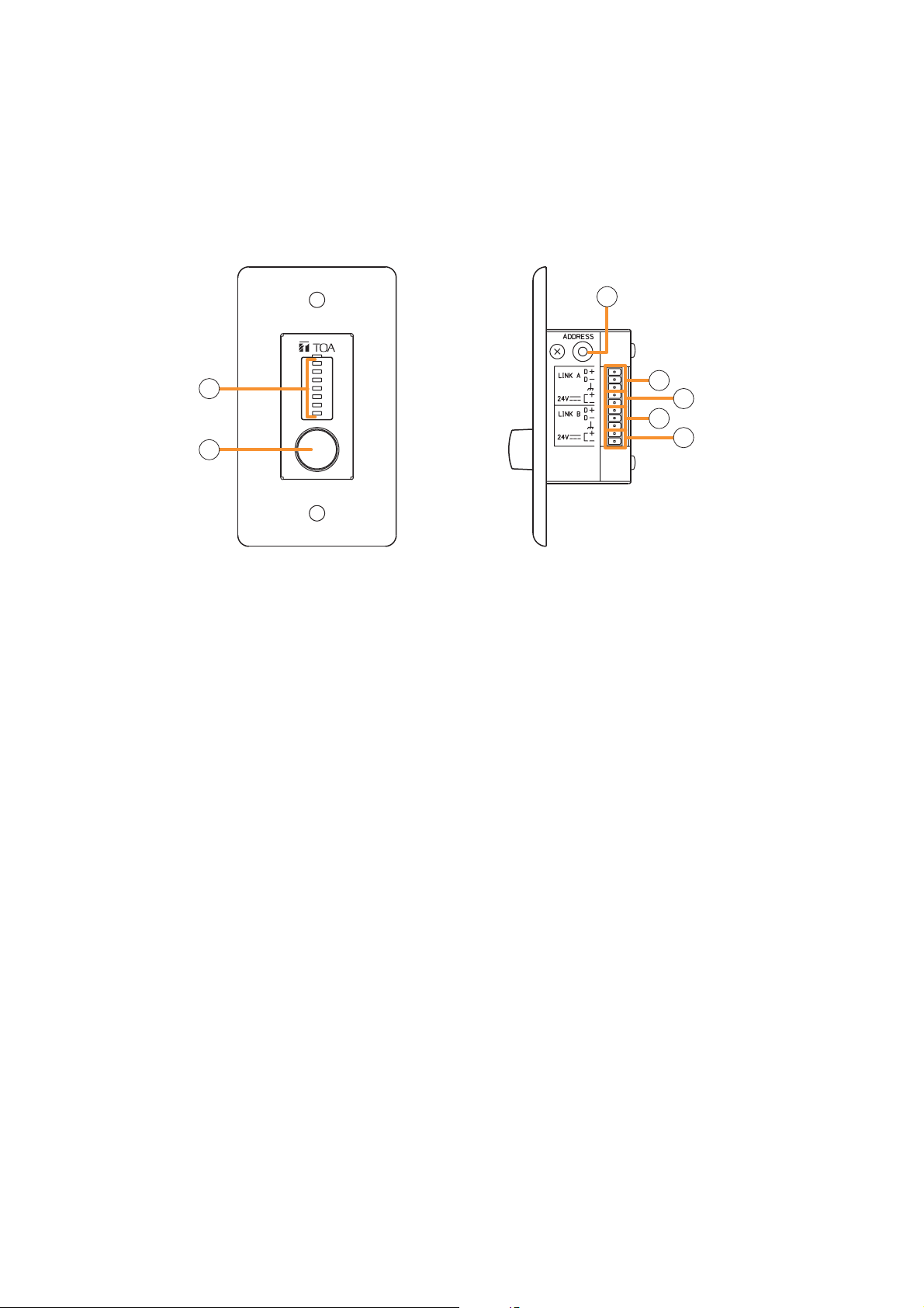
7.3.5. ZM-9011 (Remote Control Panel)
Designed to be connected to the RC-001T, the ZM-9011 is equipped with 4 buttons to perform various
controls.
The in-use indicators turn on or off synchronizing with the amplifier operation through data communications
between the ZM-9011 and the RC-001T.
It can be mounted in an American standard 1-gang electrical box.
[Front] [Side]
12
13
14
13
10
11
14
10. Control buttons
Activate the function assigned to them when pressed.
Functions to be assigned to these buttons are paging ON/OFF, cross point ON/OFF, scene switching, and
control output.
11. In-use indicators
Light when the function assigned to the button pressed is activated.
It goes off automatically after the button operation if the function in operation is activated by higher priority
equipment or reset by other equipment.
12. Address selector [0 – F]
Sets the ZM-9011 address.
Be sure to set the different address among other remote control panels.
Addresses are arranged numerically (0 – 9), and alphabetically (A – F) in this order.
13. Data terminals [LINK A/B D+, D–]
Connect the communication line to the RC-001T.
As the communication line has polarities, match both polarities of the ZM-9011 and the RC-001T when
connected.
Each 2 identical terminals is provided, and the identical terminals are internally connected to one another.
Either set of terminals can be used for connection to other controller.
14. 24 V DC input terminals [24 V +, –]
Connect the DC power cable from the RC-001T.
Each 2 identical terminals is provided, and the identical terminals are internally connected to one another.
Either set of terminals can be used for connection to other controller.
25
Page 26
7.3.6. ZM-9012 (Remote Control Panel)
Designed to be connected to the RC-001T, the ZM-9012 is equipped with a volume control knob to perform
the volume level setting on the set input or output channel.
The indicators show the volume level set by the volume control knob, that is the volume control knob position.
It can be mounted in an American standard 1-gang electrical box.
[Front] [Side]
17
15
18
19
18
16
15. Set volume level indicators
Indicate the volume level set by the volume control knob (16). The set levels are shown by 7-point LED
indicators, each of which shows -30 dB, -20 dB, -10 dB, -5 dB, 0 dB, +5 dB, and +10 dB from the bottom.
16. Volume control
Adjusts the volume level of input or output channel.
17. Address selector [0 – F]
Sets the ZM-9012 address.
Be sure to set the different address among other remote control panels.
Addresses are arranged numerically (0 – 9), and alphabetically (A – F) in this order.
18. Data terminals [LINK A/B D+, D–]
Connect the communication line to the RC-001T.
As the communication line has polarities, match both polarities of the ZM-9012 and the RC-001T when
connected.
Each 2 identical terminals is provided, and the identical terminals are internally connected to one another.
Either set of terminals can be used for connection to other controller.
19
19. 24 V DC input terminals [24 V +, –]
Connect the DC power cable from the RC-001T.
Each 2 identical terminals is provided, and the identical terminals are internally connected to one another.
Either set of terminals can be used for connection to other controller.
26
Page 27
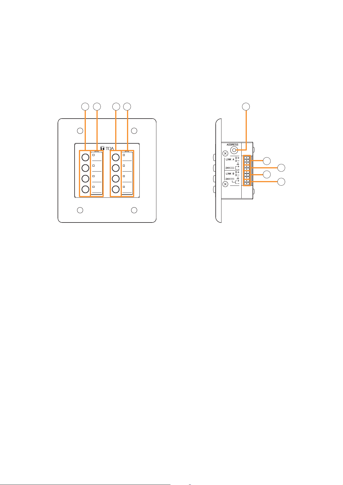
7.3.7. ZM-9013 (Remote Control Panel)
Designed to be connected to the RC-001T, the ZM-9013 is equipped with 8 buttons to perform various
controls.
The in-use indicators turn on or off synchronizing with the amplifier operation through data communications
between the ZM-9013 and the RC-001T.
It can be mounted in an American standard 2-gang electrical box.
[Front] [Side]
20 21 20 21 22
23
24
23
24
20. Control buttons
Activate the function assigned to them when pressed.
Functions to be assigned to these buttons are paging ON/OFF, cross point ON/OFF, scene switching, and
control output.
21. In-use indicators
Light when the function assigned to the button pressed is activated.
It goes off automatically after the button operation if the function in operation is activated by higher priority
equipment or reset by other equipment.
22. Address selector [0 – F]
Sets the ZM-9013 address.
Be sure to set the different address among other remote control panels.
Addresses are arranged numerically (0 – 9), and alphabetically (A – F) in this order.
23. Data terminals [LINK A/B D+, D–]
Connect the communication line to the RC-001T.
As the communication line has polarities, match both polarities of the ZM-9013 and the RC-001T when
connected.
Each 2 identical terminals is provided, and the identical terminals are internally connected to one another.
Either set of terminals can be used for connection to other controller.
24. 24 V DC input terminals [24 V +, –]
Connect the DC power cable from the RC-001T.
Each 2 identical terminals is provided, and the identical terminals are internally connected to one another.
Either set of terminals can be used for connection to other controller.
27
Page 28
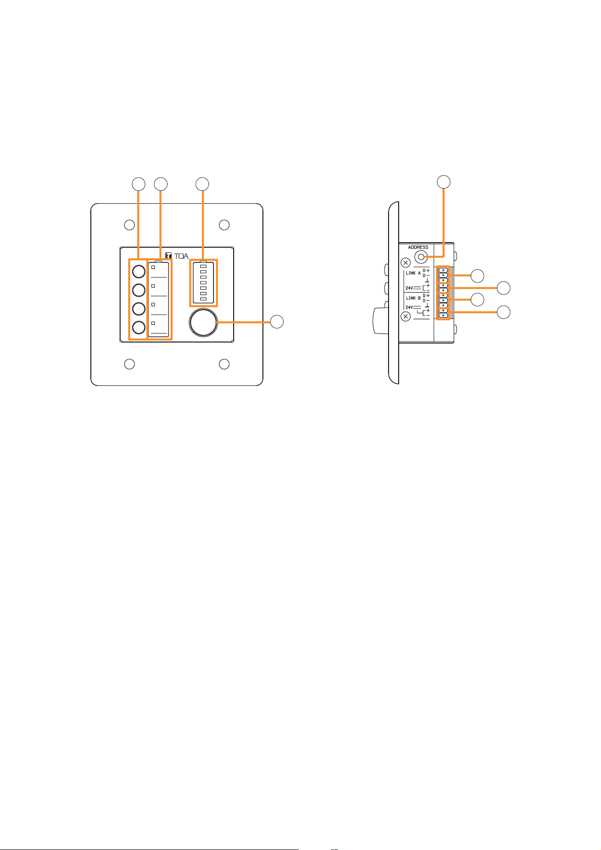
7.3.8. ZM-9014 (Remote Control Panel)
Designed to be connected to the RC-001T, the ZM-9014 is equipped with 4 buttons to perform various
controls and a volume control knob to perform the volume level setting on the set input or output channel. The
indicators show the volume level for a channel set by the volume control knob, that is the volume control knob
position.
It can be mounted in an American standard 2-gang electrical box.
[Front]
25 26 27
25. Control buttons
Activate the function assigned to them when pressed.
[Side]
29
30
31
30
31
28
26. In-use indicators
Light when the function assigned to the button pressed is activated.
It goes off automatically after the button operation if the function in operation is activated by higher priority
equipment or reset by other equipment.
27. Set volume level indicators
Indicate the volume level set by the volume control knob (28). The set levels are shown by 7-point LED
indicators, each of which shows –30 dB, –20 dB, –10 dB, –5 dB, 0 dB, +5 dB, and +10 dB from the
bottom.
28. Volume control
Adjusts the volume level of input or output channel.
29. Address selector [0 – F]
Sets the ZM-9014 address.
Be sure to set the different address among other remote control panels.
Addresses are arranged numerically (0 – 9), and alphabetically (A – F) in this order.
30. Data terminals [LINK A/B D+, D–]
Connect the communication line to the RC-001T.
As the communication line has polarities, match both polarities of the ZM-9014 and the RC-001T when
connected.
Each 2 identical terminals is provided, and the identical terminals are internally connected to one another.
Either set of terminals can be used for connection to other controller.
31. 24 V DC input terminals [24 V +, –]
Connect the DC power cable from the RC-001T.
Each 2 identical terminals is provided, and the identical terminals are internally connected to one another.
Either set of terminals can be used for connection to other controller.
28
Page 29

Function buttons and indicators on the ZM-9011, ZM-9013, and ZM-9014
The lighting mode of the operation indicator differs depending on the function assigned to the Function button.
When a communication error occurs between these remote control panels and the RC-001T module, the
lighting mode differs from that in the normal state regardless of the function assigned to the button. The
respective lighting modes are as follows.
[When the paging function is assigned to the Function button]
The indicator lights when the paging is activated by pressing the
Function button. In this event, it flashes if paging call cannot be
made because the higher-priority broadcast is in progress, and
switches to steady-on once paging call access is enabled after
the higher-priority broadcast completion.
The indicator goes off when the paging call is completed by
pressing the button again.
[When the cross point ON/OFF function is assigned to the Function button]
The indicator lights when the cross point function is enabled by
pressing the Function button, and goes off when turned OFF by
pressing the button again.
• At the time of paging activation
(When no priority broadcast is made)
(When priority broadcast is in progress)
• At the time of paging termination
(When set to ON)
(When set to OFF)
Lit
Flash
Unlit
Lit
Unlit
[When the scene recall function is assigned to the Function button]
The indicator lights when the preset scene is recalled by pressing
the Function button, and goes off when switched over to other
scene from other devices.
[When the contact control output function is assigned to the Function button]
The indicator lights when the set contact control output is turned ON by pressing the Function button.
When the button operation is set to momentary type, the output turns on and also the indicator lights as long
as the button is pressed. When the button operation is set to alternate type, the output alternates between ON
and OFF each time the button is pressed and the indicator cycles between ON (lit) and OFF (unlit) as well.
[When a communication error occurs]
The operation indicator goes off.
When the Function button is pressed, the indicator lights briefly,
then goes off.
(When the scene is recalled)
Lit
(When other scene is recalled from
other devices)
Unlit
Unlit
29
Page 30
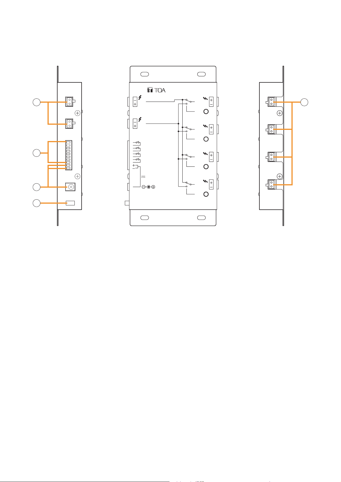
7.3.9. SS-9001 (Speaker Selector)
The SS-9001 selectively distributes each of 2 inputs to the same 4 output zones.
9000 SERIES
SPEAKER SELECTOR
32
33
34
70V/100V MAX. 240W
2
IN
70V/100V MAX. 240W
CTRL IN
ZONE 1
G
ZONE 2
G
ZONE 3
G
ZONE 4
G
DC IN
24V
120mA
ZONE 1IN 1
IN
2
ZONE 2
IN
2
ZONE 3
IN
2
ZONE 4
IN
2
35
32. Speaker input terminals [IN 1, IN 2]
2-pin removable terminal blocks.
Connect the speaker output (high impedance line, up to 240 W) from the power amplifier to each terminal.
Short the IN 2 terminal's pins when only the IN 1 terminal is used.
36
33. Control input terminal [CTRL IN]
8 pins in the 10-pin removable terminal block.
This terminal can also receive control signals from the control output terminals of the 9000 series
Amplifier or C-001T Control I/O Expansion Module.
34. DC power input terminals [DC IN]
Requires the power input of 24 V DC.
DC input terminal or 2 pins in the 10-pin removable terminal block.
Connect the power source that can supply 200 mA or more to this terminal.
The optional AD-246 AC Adapter can be used for the power supply.
35. Cord clamp
Fixes the AC adapter's power cord. (P. 119 "Power Source Connections to the SS-9001")
36. Speaker output terminals [ZONE 1/2/3/4]
2-pin removable terminal blocks.
Connect speakers to each terminal, which is capable of delivering 240 W output on a line.
30
Page 31

8. OPERATION OUTLINE
The unit can be used as a mixer amplifier or a paging amplifier depending on settings. The operation outline in
each application is described below.
8.1. Using as a Mixer Amplifier
The ideal system for speech reinforcement applications in hotel meeting rooms, churches, and conference
rooms and for sound reinforcement applications can be built.
The unit functions as a mixer amplifier to mix each input and provide audio signals at each output after audio
signal processing necessary for sound systems.
Sound adjustments tailored to environments or situations of use can be stored as up to 32 scene memories,
which can be recalled.
Other feature includes the gate function* and NOM attenuation function* that automatically adjust an input
gain.
Using these functions permits the volume levels to be controlled depending on the situation where
simultaneously broadcasting audio signals of multiple sound sources in the same space, for example, in a
ballroom or meeting room.
* Refer to p. 40, "Glossary."
CD
Power amplifier
CP-9500M2-EB or A-9500D2-AS 1CE
or
or
Speaker
Speaker
Speaker
or
Speaker
or
In this system, the remote control panel can be used to switch BGM sources.
The remote control panel is required to be set as follows using the PC setting software. For details, refer to the
separate software instruction manual.
• Source selection mode: Exclusive mode
• Function assigned to the front-mounted button: Change cross point
• Assigned value for the button: Cross points for BGM source input and output channels
Making the above settings for two or more buttons enables these buttons to perform BGM selection.
31
Page 32

8.2. Using as a Paging Amplifier
Allows input channels to have priority levels and the paging calls using these inputs to interrupt broadcasts
being made through mixing inputs.
To enable paging calls, paging settings must be performed in addition to the input/output settings. For the
paging output destination, group maximum 8 output channels to make up maximum 32 paging groups. Paging
calls are output to each zone by activating paging.
Two or more paging sources, each having one of 3 priority levels, can be set.
The higher-priority paging takes precedence over the lower-priority paging call currently being made.
Paging calls can be made not only from a conventional microphone but through PBX (extension). For the
paging setting, refer to p. 54, "Input Setting Flow Chart."
Note
Changing a scene or the setting data during paging causes the ongoing paging call to break.
So, do not make these changes during paging calls.
[Paging system outline]
Priority
level 3
Priority
level 2
No priority
level assigned
MIX
CP-9500M2-EB or
A-9500D2-AS 1CE
Power amplifier
Telephone paging
Paging
PBX
Paging microphone
Microphone
CD
8.2.1. Paging using the D-001T, D-001R, or 900 series module
When using the D-001T, D-001R, or 900 series module as paging sound source, set the Paging ON/OFF
setting (p. 58) for each input to ON. This will enable the priority level and paging group settings.
When using two or more paging sound sources, priority level can be set. For example, the following system
can be configured in a supermarket, comprising sales area and backroom area. In the sales area, BGM is
normally broadcast and announcement is made using a paging microphone. Also, it is so designed that
emergency broadcasts and paging calls can be made to the whole area using a different paging microphone.
Paging microphone
for emergency
broadcast and
all-call
Input channel 1
Paging set to ON
Priority level 1
BGM player
Paging
microphone
for sales area
Emergency
broadcast and
in-store
announcement
Backroom area
(Output channel 1)
Input channel 2
Paging set to OFF
Input channel 3
Paging set to ON
Priority level 2
CP-9500M2-EB or
A-9500D2-AS 1CE
Power amplifier
BGM broadcast and
in-store paging call
Sales area
(Output channels 2 and 3)
32
Page 33

[Operation at normal broadcasts]
Normally BGM is broadcast (Input channel 2) in the sales area. When initiating paging with a paging
microphone for sales area (Input channel 3), the paging call goes through, causing BGM volume level to
decrease.
[Operation at emergency broadcasts]
When initiating paging with a paging microphone for emergency broadcast (Input channel 1), the paging call
goes through to the whole area, causing BGM broadcast and in-store paging announcement currently being
made to decrease.
If the emergency broadcast is being made, paging cannot be initiated using a paging microphone for sales
area because it is connected to the input with lower priority level.
[Paging setting example]
Paging settings require to determine which input is to be sent to which output, and the trigger source to
activate the paging calls in addition to the priority level settings.
In this example, set the paging microphone of Input channel 1 so that it is routed to Output channels 1, 2, and
3 (whole area). Likewise, set the paging microphone of Input channel 3 so that it is routed to Output channels
2 and 3 (sales area).
Set the paging trigger to "VOX," control terminals ("C-IN1 - 4" or "C-IN1 - 12" when the C-001T is used), frontmounted buttons on the ZM-9011, ZM-9013, or ZM-9014, or front-mounted buttons on the ZM-9001 or ZM9002 (Busy input must be assigned to C-IN additionally).
In addition, telephone paging with the use of the ZP-001T can be made.
(For details of paging settings, refer to p. 46.)
8.2.2. Paging using the ZP-001T module
The ZP-001T's input is used as a paging input.
When making paging calls with the use of the ZP-001T, 3 operation modes are made available depending on
the setting.
AUTO: Automatically selects a single preprogrammed paging group when incoming call is received.
There is no need to select a paging zone.
MANUAL: Makes a paging call to the designated output with the telephone key operation (#1 - #8).
GROUP: Selects one of 8 groups with the telephone key operation (#1 - #8).
Group settings must be performed in advance.
[Telephone paging in AUTO mode
In AUTO mode, when telephone paging is initiated, the paging call is made to the designated zones without
the need to select them. This mode is convenient when always making paging calls to the whole zone or
always to the preset zone(s).
CP-9500M2-EB or A-9500D2-AS 1CE
PBX
Telephone paging
Always makes telephone
paging to this zone.
Power amplifier
Backroom area
(Output channel 1)
Sales area
(Output channels 2 and 3)
In this example, paging calls are made to the Output Channels 2 and 3 immediately after telephone paging
has been activated.
33
Page 34

[Telephone paging in MANUAL mode]
This is a method to directly select each output channel with the telephone key operation.
In this mode, if the paging zone number and the output channel number are identical, paging zones can freely
be combined with the key operation without the need to perform paging zone settings.
CP-9500M2-EB or A-9500D2-AS 1CE
PBX
Telephone paging
“0123#”
Make a paging call to
zones 1, 2, and 3.
ZONE 1
(Output channel 1)
ZONE 2
(Output channel 2)
ZONE 3
(Output channel 3)
Power amplifier
ZONE 4
(Output channel 4)
ZONE 5
(Output channel 5)
In this example, first make the paging initiation call (to be preset at the telephone) to the ZP-001T, then press
"0, 1, #" to make paging calls to Output channel 1, press "0, 2, #" to Output channel 2, or press "0, 9, #" to all
output channels.
To make paging by selecting two or more output channels, activate the paging, then press "0, 1, 2, 3, #" to
make paging calls to Output channels 1, 2, and 3, similarly press "0, 1, 4, 5, #" to Output channels 1, 4, and 5.
34
Page 35

[Telephone paging in GROUP mode]
In GROUP mode, group some output channels as paging group zones in advance. Up to 8 paging group
zones can be recalled with the telephone key operation.
This mode is effective when assigning separate paging patterns to the zones such as when the multiple output
channels are grouped to a single paging zone or when the paging zone range varies depending on conditions.
As an example, assign the outputs to the paging zones as follows in the paging group setting of the ZP-001T
Input Settings.
· Assign Outputs 1, 2, and 5 to Zone 1.
· Assign Outputs 3 and 4 to Zone 2.
· Assign Outputs 6 and 7 to Zone 3.
· Assign Output 8 to Zone 4.
CP-9500M2-EB or A-9500D2-AS 1CE
PBX
Telephone paging
“01#”
OUTPUT 1
ZONE 1
OUTPUT 2
OUTPUT 5
OUTPUT 3
OUTPUT 4
ZONE3
OUTPUT 6
OUTPUT 7
Power amplifier
ZONE 2
OUTPUT 8
ZONE 4
In such setting above, pressing "0, 1, #" causes the paging to be made to zone 1 consisting of Outputs 1, 2,
and 5. Similarly, pressing "0, 3, #" causes the paging to be made to zone 3 consisting of Outputs 6 and 7.
35
Page 36

8.2.3. Cross point ON/OFF control using the remote controller
When the cross point ON/OFF function has been assigned to the buttons on the remote controller, sound
source to be output to the output channel can be selected by pressing the button.
Two control modes are made available for the cross point ON/OFF function: "EXCLUSIVE" and
"SIMULTANEOUS."
Note: Use the PC Setting software when performing remote controller settings.
[EXCLUSIVE MODE]
Only a single cross point can be selected so as to output a single sound source to the output destination.
In this mode, only a single cross point control can be assigned to each button on the remote controller.
This is a convenient function to always select and output only one sound source using the remote controller
installed at the output destination, which is ideal for individually selecting BGM or FGM sound source to be
output to each partitioned zone (output destination).
(Example) Using as a BGM selector
Assign Input 1, 2, or 3 (BGM source) to be routed to Output 1 to each button on one remote controller.
Likewise, assign the same input channel to be routed to Output 2 to each button on the other remote
controller. (Refer to the PC Setting software screens below.)
36
Page 37

In such setting on the previous page, the remote controller with address "0" functions as a remote controller
that can switch Input 1, 2, or 3 for Output 1.
Similarly, the remote controller with address "1" functions a remote controller that can switch Input 1, 2, or 3
for Output 2.
BGM 1 player
BGM 2 player
BGM 3 player
BGM 1
BGM 2
BGM 3
Input channel 1
CP-9500M2-EB or A-9500D2-AS 1CE
Input channel 2
Input channel 3
BGM 1 BGM 3
Remote controller
with address "0"
Zone 1 (Output channel 1)
Power amplifier
BGM 1
BGM 2
BGM 3
Remote controller
with address "1"
Zone 2 (Output channel 2)
In the system above, the BGM sound source to be broadcast to Zone 1 can be selected with the buttons on
the remote controller with address "0."
Similarly, the BGM sound source to be broadcast to Zone 2 can be selected with the buttons on the remote
controller with address "1."
Notes
• When a scene memory is recalled while the cross point ON/OFF function is performed by the remote
controller, the system operation is brought into the state set in the scene memory. (Scene memory takes
precedence.)
• Paging input channel’s cross point cannot be turned ON or OFF by the remote controller.
37
Page 38

[SIMULTANEOUS MODE]
Arbitrary cross points assigned to the buttons on the remote controller can be turned ON or OFF.
Arbitrary cross points can be assigned to a single button.
This is a convenient function to individually turn ON or OFF the sound source output channel by the remote
controller installed at the output destination, which is ideal for selecting and outputting the multiple sound
sources by pressing a button on the remote controller at the output destination.
(Example) Expanding the output destination
Perform remote controller settings using the PC Setting software.
Assign cross point control to 2 buttons on the remote controller: one for cross point control to route Input 1, 2,
and 3 to Output 1, and the other for cross point control to route Input 1, 2, and 3 to Output 2. (Refer to the PC
Setting software screen below.)
In such setting above, mixed audio signals of inputs 1, 2, and 3 can be broadcast to Zone 1 (Output 1) and
Zone 2 (Output 2) as well through the remote controller operation.
38
Page 39

BGM player
Microphone
(MIC 1)
Input channel 1
Input channel 2
CP-9500M2-EB or A-9500D2-AS 1CE
Microphone
(MIC 2)
OUT 1
OUT 2
Input channel 3
Mixed audio signals
of BGM, MIC 1, and
MIC 2
Remote controller
with address "0"
Zone 1 (Output channel 1)
(When one room is partitioned into two sections)
Zone 2 (Output channel 2)
Power amplifier
No audio output
Mixed audio signals
of BGM, MIC 1, and
MIC 2
OUT 1
OUT 2
Remote controller
with address "0"
Zone 1 (Output channel 1)
(When 2 rooms are combined into one large room)
Mixed audio signals
of BGM, MIC 1, and
MIC 2
Zone 2 (Output channel 2)
Notes
• When a scene memory is recalled while the cross point ON/OFF function is performed by the remote
controller, the system operation is brought into the state set in the scene memory. (Scene memory takes
precedence.)
• When the same cross points have been assigned to the multiple buttons, the said cross point can be
controlled in the same operation each time any button is pressed.
• In-use indicator for the button lights when all the set cross points are turned to ON. When the multiple cross
points are set to be controlled by a single button, and when some points are also redundantly set to be
controlled by other buttons, the in-use indicator status may not match with the ON/OFF status of the cross
point.
• Paging input channel's cross point cannot be turned ON or OFF by the remote controller.
39
Page 40

8.3. Glossary
(1) Scene
A "Scene" is a unit of broadcast patterns when the 9000M2 amplifier is used as a mixer amplifier. Up to
32 types of patterns where various parameters are set can be saved into a Scene memory.
The saved Scene memory can be recalled, allowing operation by switching the broadcast patterns.
The following items describe the functions regarding the Scene.
(1-1) Gate function
Passes or cuts input signals depending on the input signal level. The gate opens when the input signal
level exceeds the set gate threshold level, allowing the signal to pass through. When the input signal
level falls below the gate threshold level, the gate closes after the set gate release time has passed.
This function helps to prevent unused microphone inputs from picking up noises.
The setting conditions are defined among the Gate function, NOM function, and VOX function. (Refer to
p. 42.)
(1-2) NOM (Number of Open Microphones) attenuation function
The number of open microphones (NOM) is defined as the number of open-gate input channels.
The NOM attenuation function automatically adjusts an output gain depending on the number of open
(active) microphones whose input signal level exceeds the set gate threshold level.
The output gain is attenuated by the value set on the Utility function setting screen (p. 78-C3) each time
the number of open microphones doubles.
This function prevents acoustic feedback from easily occurring when 2 or more microphones' signals
are simultaneously input.
The number of open microphones is obtained by counting all the NOM function-enabled input channels
regardless of whether the paging settings have been performed or not for these input channels.
(1-3) ANC (Ambient Noise Control) function
Adjusts the amplifier's output volume in response to the change in ambient noise level. The output
volume automatically changes as the ambient noise level goes above or below the set reference level.
This function allows the optimum output volume to be gained depending on the ambient noise level
when broadcasts are made to places where the ambient noise level changes significantly.
(2) Paging function
Allows paging calls from the input with paging priority to go through to the designated output by means of
the set paging trigger. Up to 32 paging patterns can be saved into the 9000M2 amplifier's internal
memory, and retained even if the scene is switched.
Terminating the paging calls restores the original broadcast in a fade-in manner.
(2-1) Paging settings
A combination of outputs through which paging calls are made is referred to as "Paging group."
Each paging setting can contain one input, one paging trigger, a paging group comprised of up to 8
output channels, and a combination of up to 12 interlocked contact outputs.
(2-2) Paging trigger
An event to activate paging calls.
Four types of paging triggers by means of the followings can be set: control input terminals, telephone
paging, remote activation (ZM-9001/9002, ZM-9011/9012/9013/9014), and VOX (Voice Operated
Exchange).
(2-3) VOX (Voice Operated Exchange) function
A paging trigger using the level detection function. Setting the VOX function to ON for an input channel
allows paging calls to be broadcast when the input signal level exceeds the set VOX threshold level.
If the input signal level keeps dropped below the set VOX threshold level, the paging calls are
terminated after the set VOX release time has elapsed. This function enables paging calls to be made
by use of a microphone or other input sources having no control function.
The gate and NOM functions cannot be used for the VOX-enabled input channels.
40
Page 41

(2-4) Paging priority
Each paging input channel can be set for one of the priority levels 1 to 3.
When paging calls with higher priority interrupt those with lower priority or no priority, the volumes of the
suppressed input channels are attenuated by the value set as ducker depth.
When multiple paging calls with the same priority level are activated simultaneously, calls follow the
FIFO, LIFO, or MIX setting.
(2-5) FIFO/LIFO/MIX
The order of broadcasting paging calls can be set when multiple paging calls with the same priority level
are redundantly activated. The factory default is set to the LIFO (Last-In First-Out) mode, which can be
changed using the PC Setting software.
FIFO (First-In First-Out) mode permits the preceding paging calls to take precedence to continue. The
•
later paging calls are suspended and can be resumed after the preceding calls terminate.
•
LIFO mode permits the later paging calls to take precedence to interrupt the preceding calls. The
suspended paging calls that were being made can be resumed after the later calls terminate.
MIX mode permits all paging calls to be mixed irrespective of the sequence of paging calls.
•
(2-6) Ducker depth
Sets the attenuation level on the suppressed input channels when paging calls with higher priority are
made. The signal level of each input channel is reduced by the set ducker depth from the current Scene
volume level.
This function allows paging calls to be emphasized by decreasing the volume of other broadcasts like
BGM being made using a Scene during paging calls.
(2-7) Paging output volume
The output volume for paging calls can be set separately from that set for Scene memory. The output
level is automatically switched to that set by the paging output volume when the paging call starts, and
is restored to the level set by the Scene output volume when the paging call terminates. To emphasize
paging calls over Scene broadcasts at an output destination, for example, the paging output volume can
be set larger than the Scene output volume level.
(2-8) Busy input
The control input that functions as a trigger to terminate paging calls when the paging trigger function is
assigned to the ZM-9001's or ZM-9002's button.
Paging calls are activated by pressing the ZM-9001's or ZM-9002's button irrespective of the busy input
contact's status, and terminated when the busy input contact is opened.
(2-9) Paging prohibition setting
A control input can be set for the function to prohibit one output channel from broadcasting paging calls.
If the control input set for paging prohibition function is closed during broadcasts of a paging group that
includes the paging prohibited output channel, the entire paging group calls are cancelled.
41
Page 42

[Setting conditions among the Gate function, NOM function, and VOX function]
PAG ING
Yes/ No
Yes
VOX
ON/OFF
ON
No
OFF
GATE
ON/OFF
ON
NOM
ON/OFF
OFF
Input channel
behavior
Valid parameters
Whole memory
Scene memory
VOX-triggered
Paging
GATE NOM
Release Time
(common to all Scene memories and
all input channels, unique value
in the system)
VOX
Threshhold
(Each input channel)
GATE
Threshhold
ONOFF
Input without VOX,
GATE, and NOM
NOM
Attenuation
GATE
Threshhold
42
Page 43

9. OPERATION
To operate the unit, you can use the saved Scene settings, or adjust the sound volume and tone or turn the
input/output channels on or off through the front key operation or by way of remote control with the default
settings as they are.
9.1. Basic Operation
9.1.1. Keys and knobs
Output channel ON/OFF key Memory key
Input channel ON/OFF key
[Front]
INPUT SELECT
1
2
3
4
5
6
7
8
INPUT VOLUME
ON/OFF
ON/OFF
OUTPUT SEL
OUTPUT VOLUME
MEMORY
ENTER
Input channel selection keys
Input volume control
Output channel selection key
Output volume control
9.1.2. Power ON/OFF
Power is turned on when the power switch is pressed.
To turn off the power, hold down the power switch for 0.5 second or more.
PARAMETER
Utility menu key
UTILITY
ESC/BACK
Screen shift keys
Escape/Back key
Parameter setting knob
Enter key
POWER
Power switch
Note
The power switch is a soft-switch, so the internal microcomputer is still operating even when the power switch
is set to OFF.
9.1.3. Changing the input parameters
Step 1. Press the Input channel selection key to choose the input channel for which you want to change the
volume from those with the illuminated Input channel ON/OFF indicator (channel number).
The selected channel's selection indicator (red dot) lights, and the channel name and volume level
are displayed on the VFD screen.
Step 2. Adjust the input parameters.
Adjust the volume, bass, treble, or other input parameters. (Refer to p. 54, "Input Setting Flow Chart.")
Note
To retain the set input parameters, be sure to save them in the Scene memory. Unless otherwise saved, all
the set parameters are abandoned when the AC power supply is shut off.
43
Page 44

9.1.4. Changing the output parameters
Step 1. Press the Output channel selection key to turn on the Output channel selection indicator (red dot) for
the output channel for which you want to change volume.
Channels to be selected will change each time the Output channel selection key is pressed.
The channel name and volume level are displayed on the VFD screen.
Step 2. Adjust the output parameters.
Adjust the volume, bass, treble, or other output parameters.
(Refer to p. 69, "Output Setting Flow Chart.")
Note
To retain the set output parameters, be sure to save them in the Scene memory. Unless otherwise saved, all
the set parameters are abandoned when the AC power supply is shut off.
9.1.5. Input channel ON/OFF
Input channels alternate between ON and OFF with each depression of the Input channel ON/OFF key.
The channel is ON when the input channel ON/OFF indicator (channel number) lights.
9.1.6. Output channel ON/OFF
Output channels alternate between ON and OFF with each depression of the Output channel ON/OFF key.
The channel is ON when the Output channel ON/OFF indicator (channel number) lights.
Display Saver Mode
The VFD automatically enters the display saver mode if no key is operated for 20 minutes.
In this mode, “DISPLAY SAVER MODE. PRESS ANY KEY” indication scrolls sideways on the VFD.
The VFD reverts to normal if any key is pressed.
This one touch key operation performs only to restore the VFD to normal operating state. Subsequent
key operation is effective for the amplifier operation.
44
Page 45

9.2. Recalling Scene Memory
A "Scene" defines the unit of broadcast pattern.
Up to 32 patterns can be stored as Scene memory in the Scene memory bank, which can then be recalled.
Step 1. Press the Memory key to display the Scene memory setting
screen.
Step 2. Press the Right shift key to display the Scene memory recall
screen.
Step 3. Select with the Parameter setting knob the Scene memory bank
number to be recalled.
Step 4. Press the Right shift key.
After recall completion, the Scene memory bank number and
memory name are displayed.
–
SCENE
01 1
MEMORY
1
NESSCE ETT I NG LOAD
2
LOA D 0 1 S C E N E 1
PARAMETER
3
LOAD 03
MORN I N
G
4
03–MO
RN I NG
45
Page 46

9.3. Making Zone Paging
Close (make contact)
Open (break contact)
Contact input
Contact input
To make the zone paging broadcast setting easier, clarify the following points before performing the setting.
· Input (source) to access paging broadcast
· Paging trigger and paging destination zones
· Equipment or function to be interlocked with paging
Paging settings are described below.
9.3.1. Zone paging using the D-001T, D-001R, or 900 series module
When using the D-001T, D-001R, or 900 series module for paging input, the paging function for the input
channel must be set to ON in the input settings.
The paging-enabled input channel is set as a paging source, enabling the priority setting, paging trigger
setting, and paging output destination setting.
For each setting item, refer to p. 54, "Input Setting Flow Chart."
Notes
• If the paging setting of an input channel is changed to OFF from ON during paging, the paging using the
input channel is made to terminate.
• When the paging-enabled input channel is muted, paging can be initiated but the paging call will be muted.
[Paging initiation by means of the control terminal]
When the paging broadcast is initiated by closing the control
terminal (make contact), the following operations are carried
out.
Step 1. Close the paging function assigned-control input terminal.
Step 2. Make a paging call.
Step 3. Open the input terminal that has been closed in the step 1.
Paging terminates, restoring the level of the mixed audio signal to
The level of the mixed audio signal being broadcast at the
paging destination decreases.
The level of the mixed audio signal being broadcast at the
paging destination decreases.
the original value.
46
Page 47

[Paging initiation by the ZM-9011, ZM-9012, ZM-9013, or ZM-9014 operation]
When assigning the paging activation function to the button on the remote control panel, pressing the functionassigned button causes the paging to initiate.
Step 1. Press the button on the remote control panel.
The corresponding indicator lights.
The level of the mixed audio signal being broadcast at the
paging destination decreases.
When the selected channel is being used by other paging
with higher priority level, the indicator does not light,
indicating that paging cannot be initiated.
Step 2. Make a paging call.
Step 3. Press the button again to terminate the paging call,
restoring the level of the mixed audio signal to the original
value.
Example: ZM-9011
Lights
1
3
[Paging initiation using VOX (voice-operated switch) trigger]
Initiates paging when the paging audio signal is detected. There is no need to prepare a control input
additionally as it starts paging by detecting the presence of audio signal. In this case, special attention should
be paid to audio dropout at the beginning of paging call or unintentional start of paging.
The VOX function is available when the D-001T or D-001R module is used.
Step 1. Speak into the paging microphone connected to the input
of which trigger is set to VOX.
CP-9500M2-EB or A-9500D2-AS 1CE
When the audio signal is detected, the paging call goes
through, decreasing the level of the mixed audio signal
being broadcast at the paging destination.
Step 2. Terminate the paging call.
If the audio signals are not detected for a specified period
of time at the paging input, paging is made to terminate.
47
Page 48

9.3.2. Zone paging using the ZP-001T module
This section describes the method of initiating zone paging from a PABX (extension telephone) using the ZP001T Zone Paging Module. The following 2 operation modes are available for the ZP-001T: Paging port mode
and Ring signal mode.
In both operation modes, when any of the following situations arises, the ZP-001T will not receive calls from
the PABX or paging calls will be muted. Even when paging calls are muted, since the line is kept connected,
they resume after the situation is restored.
• The input channel for the ZP-001T is turned off.
The ZP-001T will not receive calls from the PABX.
When this is done during paging calls by way of the ZP-001T, paging calls are muted.
• The input channel for the ZP-001T is muted by way of the control input.
The ZP-001T can receive calls from the PABX, but paging calls are muted.
When this is done during paging calls by way of the ZP-001T, paging calls are muted.
• Emergency-mute (EMG-MUTE) is activated by way of the control input.
The ZP-001T can receive calls from the PABX, but paging calls are muted.
When this is done during paging calls by way of the ZP-001T, paging calls are muted.
[Paging port mode]
Step 1. Activate the paging port from the extension telephone.
Since this method differs depending on the type of exchange, please read the instruction manual for
the extension telephone.
When the paging port is activated and the control input terminal is closed, the ZP-001T module
connects the line.
Step 2. Select the output channel.
The output selection method differs as follows depending on the paging method setting made on the
VFD screen.
[Manual]
Press [0] first, followed by the output channel number ([1] – [8] or [9] when selecting all numbers
simultaneously). Pressing the [#] key completes the output channel selection.
Example: To select Outputs 2 and 3, press [0] [2] [3] [#].
To make an all-zone call, press [0] [9] [#].
[Zone Group]
Press [0] first, followed by the group number [1] – [8]. Pressing the [#] key completes the group
selection. Only a single group can be selected.
[Auto]
Automatically selects the output channel.
Step 3. Begin paging.
When the pre-paging tone is set to ON (p. 64-A26), begin paging after the tone sounds.
When the selected output channel is being used by other broadcast with higher priority level, a busy
tone is heard from the handset, indicating that paging cannot be performed.
Step 4. Deactivate the paging port to terminate paging.
Since this method differs depending on the type of exchange, please read the instruction manual for
the extension telephone.
48
Page 49

[Ring signal mode]
Step 1. Make a call from the extension telephone to the ZP-001T module.
After a calling tone sounds twice, the ZP-001T receives the call and a callback tone is heard from the
handset.
Step 2. Select the output channel.
The output selection method differs as follows depending on the paging method setting made on the
VFD screen.
[Manual]
Press [0] first, followed by the output channel number ([1] – [8] or [9] when selecting all numbers
simultaneously). Pressing the [#] key completes the output channel selection.
Example: To select Outputs 2 and 3, press [0] [2] [3] [#].
To make an all-zone call, press [0] [9] [#].
[Zone Group]
Press [0] first, followed by the group number [1] – [8]. Pressing the [#] key completes the group
selection. Only a single group can be selected.
[Auto]
Automatically selects the output channel.
Step 3. Begin paging.
When the pre-paging tone is set to ON (p. 64-A26), begin paging after the tone sounds.
Paging can be performed within 30 seconds or 10 minutes after the call gets through. After this preset
time have elapsed, the line is automatically disconnected.
When the selected output channel is being used by other broadcast with higher priority level, a busy
tone is heard from the handset, indicating that paging cannot be performed.
Step 4. To terminate paging, press [0] [0] [#], and then replace the handset.
If dialing [0] [0] [#]: Pressing a first [0] terminates paging (a DTMF tone for the first [0] is output), and
the ZP-001T disconnects the line after the [#] has been pressed.
If replacing the handset without dial operation: After a signal tone is transmitted about 3 times, the
paging is terminated and the line disconnected.
49
Page 50

9.4. Releasing Key Lock
The key lock function prevents the front-mounted keys or knobs from being tampered. (Refer to p. 90 "Key
Lock Function Setting.")
You can temporarily operate the locked keys by entering a password to unlock them. Operation after
password entry differs depending on the locked keys.
Step 1. Press the locked key.
The password entry screen is displayed with the flashing
indication of the character entry position on the extreme left.
Note
If the front-mounted key operation is locked, the password
entry screen appears after you press the input or output
selection key and attempt to rotate the input or output volume
control.
Step 2. Press the Enter key if no password has been set.
If the password has been set, enter it using the Input channel
selection keys.
Entering a character causes the next character entry position
to flash for character entry.
When the entered password is correct, the locked key is
released. If the registered password is comprised of 1 to 3
characters, as soon as entered 1 to 3 characters agree with
them, the locked key is released.
When released keys are those of the type related to input and
output operations, they become temporarily operable, but
revert to the locked state if they are left unused for 1 minute.
When utility-related keys are released, the key lock menu
screen is displayed, clearing the password setting
automatically.
Move to the screen for which you want to make a change.
When wishing to lock the keys using the password even after
the setting has been changed, set the password again. (Refer
to p. 91 "Password setting.")
To simultaneously release all locked keys, set the all-key lock
function to OFF on the all-key lock ON/OFF setting screen.
(Example when input keys are locked)
–
SCENE
01 1
INPUT SELECT
3
IN3–IN3 ON 00
ENTERPASSWO
ENTERPASSWO
ENTERPASSWO
IN3–IN3 ON 00
:
INPUT VOLUME
RD ____
INPUT SELECT
2
RD ___
INPUT SELECT
6
RD
:
1
.
2
.
When the power switch is locked, pressing it displays the
password entry screen. In this case, the power cannot be
turned off without releasing the key lock.
Since the key lock function helps to prevent the front panel
keys or knobs from being tampered, their operation can be
performed by controls through the control input terminals
even if the keys or knobs are locked.
50
Page 51

9.5. Operation Example
The operation procedure is described here using an example to change the output parameters after recalling
the Scene memory when the output operation key is locked.
–
Step 1. Press the Memory key to display the Scene memory setting
screen.
SCENE
01
NESSCE ETT I NG LOAD
1
MEMORY
1
Step 2. Press the Right shift key to display the Scene memory recall
screen.
Step 3. Select with the Parameter setting knob the Scene memory
bank number to be recalled.
Step 4. Press the Right shift key.
Step 5. Press the output channel selection key.
The selected output channel status is displayed.
Step 6. Rotate the output volume control knob or press any screen
shift key.
The password entry screen is displayed with the leftmost
character position flashing.
Step 7. Enter the password with the input channel selection keys.
The locked key is released when the entered password is
correct.
2
LOAD 0 1 SCENE1
PARAMETER
3
LOAD 05 LECT URE
4
05 – LECTURE
OUTPUT SEL
5
O
UT1 –OUT1 ON 10
:
6
ENTERPASSWO
RD ____
INPUT SELECT
2
INPUT SELECT
6
7
.
Step 8. Use the Up, Down, Left and Right shift keys to display the
desired setting screen.
Step 9. Change the parameter with the Parameter setting knob.
Step 10. Press the Escape/Back key until the scene memory screen
(normal use state screen) is displayed.
The display returns to the Scene memory indication screen.
ENTERPASSWO
O
UT1 –OUT1 ON 10
RD
:
.
8
or
ENTER
BASS + 1 2 TREB L E – 1 0
PARAMETER
9
BASS + 1 5 TREB L E – 1 0
ESC/BACK
10
Press twice.
0 5 – LECTURE
51
Page 52

10. SETTINGS
Use the VFD screen, keys, and Parameter setting knob on the unit's front panel to make settings.
Settings are categorized into two types of items: Items recommended to be set before operation (input
settings, audio output settings, and UTILITY settings), and items that limit the front panel's key and knob
operation (keylock settings, which are a part of UTILITY settings). If settings have been made before
operation, all such settings can be stored using a Scene memory function. Ongoing paging calls are forced to
terminate if paging function-related setting is changed during paging calls. Note that paging is not interrupted if
settings other than paging function are changed.
All settings that can be made at the unit can also be made using the supplied dedicated software. (Refer to
the separate setting software instruction manual.)
10.1. Setting Menu Configuration and Flow for Entering Each Screen
The setting menu consists of four major setting items: Input setting, Output setting, UTILITY setting, and
Scene memory setting. The method to enter each setting screen differs as shown below.
Refer to each individual setting flow chart for details such as the parameter settings and key operations to shift
the screen.
10.1.1. Input setting configuration
Set paging ON/OFF, input sensitivity, and bass/treble parameters for each individual input channel.
Pressing the Input channel selection key (1 - 8) corresponding to the desired channel number at the normal
use state screen allows you to enter its input channel setting screen. Setting items differ depending on the
modules used for input channels.
INPUT SELECT
1
0 1 – S C E N E 1
I N 1 : O F F
1 –
I N
I N 1 : O N 0. 0 d B
I N
1 –
Each individual item setting
Setting for the channel on
which the D-001T/R is used
(Refer to p. 54)
Setting for the channel on
which the ZP-001T is used
(Refer to p. 56)
Setting for the channel on
which the AN-001T is used
(Refer to p. 57)
10.1.2. Output setting configuration
Set parameters such as bass/treble, equalizer, and compressor for each individual output channel.
Press the Output channel selection key several times at the normal use state screen to display the desired
channel number. The display proceeds to its output channel setting screen.
OUTPUT SEL
0 1 – S C E N E 1
O U
T 1 –
O U T 1 : O F F
O U
T 1 –
O U T
1 :
O N – 2 0. 0 d B
Each individual item setting
Refer to p. 70.
52
Page 53

10.1.3. Utility setting configuration
Perform stereo link settings for the input and output channels, function assignment to the control input and
output terminals, keylock settings, and password setting.
Press the Utility key at the normal use state screen to proceed to the setting screen.
UTILITY
0 1 – S C E N E 1
Each individual item setting
Refer to p. 75.
10.1.4. Scene memory setting configuration
Perform scene memory recall, scene memory save, and scene memory erasure.
Press the Memory key at the normal use state screen to proceed to the setting screen.
MEMORY
0 1 – S C E N E 1
Each individual item setting
Refer to p. 91.
10.1.5. Confirming set items
Each setting item consisting of the related elements to be set is confirmed by pressing the Enter key or right
shift key after these elements have been all set.
If the setting flow is reversed half way through a setting item, the parameters having been set so far are
abandoned.
Example: Paging setting on the D-001T or D-001R use channel (Refer to p. 55-A16 - A20.)
(p.61-A16)
P A G I N G 0 1 I N 1 -> O U T 1
• Select Control output.
• Press Enter key.
(p.62-A20)
P A G I N G S Y N C O F F
• Set paging-interlocked control output to OFF.
• Press Enter key.
All parameters set for the paging item are
confirmed at this step and written in the
amplifier's internal memory.
(p.62-A17)
P A G I N G T R I G C - I N
• Select Trigger.
• Select C-IN.
• Press Enter key.
(p.62-A19)
P A G I N G T R I G C I N 0 1
• Set CIN01 for Control output terminal.
• Press Enter key.
(p.61-A16)
P A G I N G 0 1 I N 1 -> O U T 1
Display returns to the beginning.
53
Page 54

54
10.2.1. Input setting flow chart for the channel on which the D-001T or D-001R is used
10.2. Input Setting Flow Chart
Setting items differ depending on the modules used for input channels.
Refer to this page when the D-001T or D-001R is used, p. 56 when the ZP-001T is used, and p. 57 when the AN-001T is used.
Normal use state
0 1 - S C E N E 1
INPUT SELECT
1
To/from lowermost screen
I-ON/OFF
I N 1 - I N 1 : O F F
I N 1 - I N 1 : O N 0. 0
: -∞, -70 to +10 (0.5 dB steps)
IN
(p.58-A2)
I N 1
- - - - - - -
(p.58-A3)
I-ON/OFF
P A G I N G O F F P A G I N G O N
P
or
(p.58-A4)
I N 1 - S E N S I T I V I T Y - 1 0
(p.59-A5)
I N 1 - P H A N T O M O F F
(p.58-A1)
INPUT SELECT
1
: Cycles meter display (FADER /LEVEL) below
the setting screen each time pressed.
: Selects characters to enter.
P
(Right shift key): Moves the cursor to the right.
P
-
60, -54, -48, -42, -36, -30, -24, -18, -10 (dB)
:
I-ON/OFF
P
or : ON/OFF
The screen display examples may differ from actual displays.
The on-screen indications shown in blue are variable parameters
by key operation.
The symbols in the figure represent the following key operation.
: Screen shift keys (up and down)
: Screen shift key (right) or ENTER key
: Screen shift key (left) or ESC key
: PARAMETER knob
P
IN
: INPUT VOLUME knob
I-ON/OFF
: Input channel ON/OFF key
O-ON/OFF
: Output channel ON/OFF key
When Paging is set to OFF, or when Paging is set to ON and Trigger set to any type except VOX
(p.59-A6)
I N 1 - GATE - O FF I N 1 -GATE - O N
I-ON/OFF
or
(p.59-A6)
P
(p.59-A7)
GATE - THRESHOLED - 30 d B
When Paging is set to OFF, or when Paging is set to ON and Trigger set to any type except VOX
GATE ON: NOM selectable, GATE OFF: NOM fixed to OFF
I-ON/OFF
I N 1 - N O M - O FF I N 1 - N O M - O N
P
or
(p.59-A9)
B A S S 0 T R E B L E 0
P
: -12 to +12
(1 dB steps)
(p.59-A8)
(p.59-A9)
B A S S 0 T R E B L E 0
P
: -12 to +12
(1 dB steps)
(p.59-A10)
L O U D N E S S - O F F
I-ON/OFF
P
or : ON/OFF
P
:
-
5 to -40 dB
(5 dB steps)
To the next page
Page 55

55
From the previous page
(p.60-A11)
E Q - O F F
(p.60-A12)
H P F - O F F L P F - O F F
(p.60-A13)
C O M P R E S S O R - O F F
Only when Paging is set to ON
(p.61-A14)
P R I O R I T Y 3
Only when Paging is set to ON
(p.61-A16)
P A G I N G 0 1 I N 1 -> O U T 1
P
: 1 to 32
When Trigger is set to "VOX,"
only one can be created.
When set to OFF, setting menu at
right is not displayed.
(p.60-A11)
E Q 0 1 0 d B Q 1. 5 3 1. 5
P
: 1 to 10
(p.60-A12)
H P F - O F F L P F - O F F
P
: OFF,
20 to 20k (Hz),
31 points
P
: OFF, 1, 2, 3, 4, 5
(p.61-A15)
D U C K E R - D E P T H O F F
P
: 1, 2, 3
P
: OFF, -50, -40, -30, -20, -10, 0 (dB)
(p.61-A16)
P A G I N G 0 1 I N 1 -> O U T 1
: Selects OUT.
P
O-ON/OFF
: Confirms the setting.
Goes to the next band setting.
(p.60-A11)
E Q 0 1 0 d B Q 1. 5 3 1. 5
P
:
-
12 to +12 (1 dB steps)
P
: OFF,
20 to 20k (Hz),
31 points
(p.62-A17)
P A G I N G T R I G V O X
P A G I N G T R I G C - I N P A G I N G T R I G N O N E
(p.60-A11)
E Q 0 1 0 d B Q 1. 5 3 1. 5
P
: 0.3 to 5
(p.62-A18)
VOX - T H R E S H O L D - 3 0
P
: -40 to -5
P
(5 dB steps)
(p.62-A19)
(p.60-A11)
E Q 0 1 0 d B Q 1. 5 3 1. 5
P
(p.62-A20)
P A G I N G S Y N C O F F
P
P A G I N G S Y N C O N
: 20 to 20k (Hz)
(p.62-A21)
S Y N C O U T C - O U T 0 1
P
or
O-ON/OFF
: 1 to 12
: (ON), -(OFF)
When Paging is set to OFF
(p.64-A25)
I N 1 -> O U T 1 0
To/from uppermost screen
O-ON/OFF
(p.64-A25)
I N 1 -> O U T 1 0
: Selects OUT.
P
: Confirms the setting.
P
-
∞, -70 to +10
:
(1 dB steps)
P
(p.63-A22)
P A G I N G T R I G Z M I D = 1 -> N O N E
P
: RMT1, RMT2, 1 to 16
(p.63-A23)
I D = R M T 1 -> Z M - 9 0 1 1 S W 1
P
: RMT1, 2=NONE, 9001, 9002
ID1 to 16=NONE, 9011, 9013, 9014
(p.63-A24)
I D = R M T 1 -> Z M - 9 0 1 1 S W 1
P
: 9002, 9011, 9014=SW1 to 4
9001=SW1 to 6
9013=SW1 to 8
Page 56

56
10.2.2. Input setting flow chart for the channel on which the ZP-001T is used
To/from lowermost screen
INPUT SELECT
Normal use state
0 1 - S C E N E 1
1
I N 1 - I N 1 : O F F
I-ON/OFF
I N 1 - I N 1 : O N 0. 0
: -∞, -70 to +10 (0.5 dB steps)
IN
(p.58-A2)
I N 1
- - - - - - - -
(p.64-A26)
P R E P A G I N G - O F F
(p.64-A27)
M O D E => P A G I N G P O R T
(p.58-A1)
INPUT SELECT
1
: Cycles meter display (FADER /LEVEL) below
the setting screen each time pressed.
: Selects characters to enter.
P
(Right shift key): Moves the cursor to the right.
I-ON/OFF
P
or : ON/OFF
P
: RINGING SIGNAL, PAGING PORT
The screen display examples may differ from actual displays.
The on-screen indications shown in blue are variable parameters
by key operation.
The symbols in the figure represent the following key operation.
: Screen shift keys (up and down)
: Screen shift key (right) or ENTER key
: Screen shift key (left) or ESC key
: PARAMETER knob
P
IN
: INPUT VOLUME knob
I-ON/OFF
: Input channel ON/OFF key
O-ON/OFF
: Output channel ON/OFF key
(p.64-A28)
P R I O R I T Y 2
P
: 1, 2, 3
(p.61-A15)
D U C K E R - D E P T H O F F
P
: OFF,
-
50, -40, -30, -20, -10, 0 (dB)
(p.64-A29)
P A G I N G T I M E 3 0
(p.65-A30)
P A G I N G : M A N U A L
P
P
: 30 (sec), 10 (m)
(p.65-A31)
G R P 0 1 I N 1 -> MANU
P
: 01 to 32
(p.65-A31)
P A G I N G : AUTO G R P 0 1 I N 1 -> O U T 1
P
: 01 to 32
P
(p.65-A33)
P A G I N G : Z O N E G R O U P 1 G R P 0 1 I N 1 -> O U T 1
P
: 1 to 8
(p.65-A32)
P A G I N G : I N 1 -> O U T 1
P
: Selects OUT.
O-ON/OFF
: Confirms the setting.
(p.65-A34)
1 G R P 0 1 I N 1 -> O U T 1
P
: 01 to 32
(p.65-A35)
1 G R P 0 1 I N 1 -> O U T 1
P
: Selects OUT.
O-ON/OFF
: Confirms the setting.
(p.62-A20)
P A G I N G S Y N C O F F
P
P A G I N G S Y N C O N
(p.62-A21)
S Y N C O U T C - O U T 0 1
P
: 1 to 12
or
O-ON/OFF
: (ON),
-
(OFF)
To/from uppermost screen
Page 57

57
10.2.3. Input setting flow chart for the channel on which the AN-001T is used
Normal use state
0 1 - S C E N E 1
To/from lowermost screen
INPUT SELECT
1
A N C 1
-
I N 3
INPUT SELECT
1
: Cycles meter display (FADER /LEVEL) below the setting screen each time pressed.
(p.66-A36)
P
A N C 1 -
- - - - - - -
: Selects characters to enter.
(Right shift key): Moves the cursor to the right.
(p.66-A37)
A N C 1 - B Y P A S S A N C 1 - ACTIVE
P
(p.66-A38)
A N C - S E N S I T I V I T Y - 1 0
P
:
-
60, -54, -48, -42, -36, -30, -24, -18, -10 (dB)
(p.66-A39)
A N C - P H A N T O M O F F
I-ON/OFF
P
or : ON/OFF
(p.66-A40)
A N C - A P P L I E S -> O U T 1
P
: Selects OUT.
(p.67-A41)
I-ON/OFF
M O N I T O R O U T - O F F M O N I T O R O U T - O N
P
or
(p.67-A42)
M O N I T O R O U T - O U T 4
P
: Selects OUT.
The screen display examples may differ from actual displays.
The on-screen indications shown in blue are variable parameters
by key operation.
The symbols in the figure represent the following key operation.
: Screen shift keys (up and down)
: Screen shift key (right) or ENTER key
: Screen shift key (left) or ESC key
: PARAMETER knob
P
: Input channel ON/OFF key
I-ON/OFF
(p.67-A43)
M A X I M U M L E V E L 0
P
-
:
-
(p.67-A45)
S A M P L E T I M E 2 0
(p.68-A46)
G A I N , R A T I O 3 : 3
(p.68-A47)
A N C A D J 0 S E N S - 5 0
To/from uppermost screen
15, -12, -9,
6, -3, 0 (dB)
P
: 10, 15, 20, 30, 60, 120, 180, 300 (sec)
P
: 6:3, 5:3, 4:3, 3:3, 3:4, 3:5, 3:6, 6:
5:
P
-
:
(p.67-A44)
M I N I M U M L E V E L - 6
P
-
18, -15, -12, -9, -6, -3 (dB)
:
-
3, 4:-3, 3:-3, 3:-4, 3:-5, 3:-6
10 to +10 (1 dB steps)
-
3,
Page 58

10.2.4. Input setting items
Unless otherwise specified, use the Parameter setting knob for each parameter selection.
(A1) Input gain setting
I N 1 - I N 1 : O N 0. 0
Select the input channel using the Input channel selection key.
Confirm the selection by setting the Input channel ON/OFF key to ON.
Set the input channel gain using the Input volume control.
Setting Range
(A2) Input channel name setting
I N 1
- - - - - - -
The flashing portion is the cursor position for entering channel name characters.
Select a character from the alphanumeric character list by rotating the Parameter setting knob, then move the
cursor with the Right shift key.
Entering a new name overwrites the existing name, if there is.
To delete the character, select [ _ ] (under-bar) with the Parameter setting knob. A space character cannot be
entered.
Up to 7 characters can be used to set the name.
Even when an input channel name has been set, some setting screens display the channel number, not the
set name.
When an input channel is stereo-linked (p. 78-C1), the name entry screen only for the odd channel is
displayed.
Input Channel Selection
Channel Control
Channel Gain
7 characters (default: IN1 – 8)Setting Range
1 – 8 (default: 1)
ON (default), OFF
–∞, –70.0 dB to +10.0 dB (default: 0.0 dB), 0.5 dB steps
(A3) Paging ON/OFF setting
P A G I N G O F F
Set whether or not to use this input channel for paging.
When set to ON, this channel can be used as paging source, enabling priority setting and zone paging setting
as well.
ON, OFF (default)Setting Range
Note
Changing the parameter in this item during paging broadcast interrupts all paging calls being made through
any channel.
(A4) Input Sensitivity setting
(when the D-001T/R is used)
I N 1 - S E N S I T I V I T Y - 1 0
Select the input sensitivity from the following 9 levels depending on the input sources:
Setting Range
–60, –54, –48, –42, –36, –30, –24, –18, –10 dB (default)
58
Page 59

(A5) Phantom power ON/OFF setting
(A10) Loudness compensation setting (when the D-001T/R is used
L O U D N E S S - O F F
I N 1 - G A T E - O F F
(A6) GATE setting (On the D-001T/R input channel, when Paging is set to OFF,
or when Paging is set to ON and Trigger set to any type except VOX.)
(when the D-001T/R is used)
I N 1 - P H A N T O M O F F
Set the Phantom power to ON or OFF.
Notes
• When the module is the D-001R, this function can be set to ON but cannot be output.
• The Phantom power cannot be set to ON for the stereo-linked input channel.
Setting Range
• ON: Supplies the phantom power. (except D-001R)
• OFF: Does not supply the phantom power.
Set the GATE function to ON or OFF.
Setting Range
• ON: Activates the GATE function.
• OFF: The GATE function does not work.
(A7) GATE threshold setting (when GATE is set to ON)
G ATE - THRESHOLD - 30 dB
Rotate the Parameter setting knob to set the GATE threshold.
(A8) NOM attenuation ON/OFF setting (On the D-001T/R input channel, when Paging
is set to OFF, or when Paging is set to ON, Trigger to any type except VOX, and GATE to ON.)
ON, OFF (default)
ON, OFF (default)
–40 dB to –5 dB (default: –30 dB), 5 dB stepsSetting Range
I N 1 - N O M - O FF
Set the NOM attenuation function (p. 40 "Glossary") to ON or OFF.
This function relates to the Gate ON/OFF setting and Gate threshold setting that appear later.
The NOM attenuation cannot be set to ON for the stereo-linked input channel.
Setting Range
• ON: Activates the NOM attenuation function.
• OFF: The NOM attenuation function does not work.
(A9) BASS and TREBLE settings (when the D-001T/R is used)
B A S S 0 T R E B L E 0
Rotate the Parameter setting knob to set gains.
Press the Right or Left shift key to select BASS or TREBLE, of which gain value that flashes can be adjusted.
Setting Range
Rotate the Parameter setting knob to set the loudness compensation function ON/OFF.
Setting ON boosts low frequencies.
ON, OFF (default)
–12 dB to +12 dB (default: 0 dB), 1 dB steps
Setting Range
ON, OFF (default)
59
Page 60

(A11) EQ ON/OFF, Band number, Gain, Q, and Center frequency settings (when the D-001T/R is used)
E Q 0 1 0 d B Q 1. 5 3 1. 5
Band number Q Center frequency
Gain
The indications on the right of "EQ" turn on and off as the Parameter setting knob is rotated.
When the indication is displayed, EQ is ON and a band number, gain, Q, and center frequency are displayed
in this order from left to right. Use the Parameter setting knob to change each parameter, and the Left and
Right keys to move the setting items.
Setting Range
(A12) HPF and LPF settings (when the D-001T/R is used)
H P F - O F F L P F - O F F
Rotate the Parameter setting knob to set the cut-off frequencies.
Press the Right or Left shift key to select HPF or LPF, of which parameter that flashes can be adjusted.
Setting Range
(A13) Compressor setting (when the D-001T/R is used)
EQ
EQ Band Number
Gain
Q
Center Frequency
HPF
LPF
ON, OFF (default)
01 to 10 (default: 01)
–12 dB to +12 dB (default: 0 dB), 1 dB steps
0.3, 0.5, 0.7, 1, 1.5 (default), 2, 3, 5
20, 25, 31.5 (default), 40, 50, 63, 80, 100, 125, 160, 200, 250, 315,
400, 500, 630, 800, 1 k, 1.25 k, 1.6 k, 2 k, 2.5 k, 3.15 k, 4 k, 5 k,
6.3 k, 8 k, 10 k, 12.5 k, 16 k, 20 kHz
OFF (default), 20, 25, 31.5, 40, 50, 63, 80, 100, 125, 160, 200,
250, 315, 400, 500, 630, 800, 1 k, 1.25 k, 1.6 k, 2 k, 2.5 k, 3.15 k ,
4 k, 5 k, 6.3 k, 8 k, 10 k, 12.5 k, 16 k, 20 kHz
C O M P R E S S O R - O F F
Setting Range
Use the compressor to prevent power amplifier overload or to produce more easily heard sound by averaging
the audio level. The number shows the compressor's effectiveness level as shown in the table on the next
page, which can be set by rotating the Parameter setting knob.
• DEPTH = 1 (Peak limiter)
Provides a peak limiter function that protects amplifiers and speakers against damage caused by an
excessive signal input.
This level is suited to speech applications.
• DEPTH = 2 (Peak limiter)
Provides a peak limiter function that protects amplifiers and speakers against damage caused by an
excessive signal input.
This level is suited to musical applications.
• DEPTH = 3 (Sonic normalizer)
Equalizes the sound volume of reproduced BGM among CDs or pieces of music by boosting small sounds
and lowering big sounds, making the entire sound volume uniform.
This level is suited to BGM reproduction.
• DEPTH = 4 (Speech leveler)
Makes paging calls easier to hear by equalizing the difference in speech signal volume that may result from
individual differences in speaker voice volumes or variations in speaker-to-microphone distances.
Since the volume is extensively corrected, the feedback margin narrows, making it liable to occurrences of
feedback. Therefore, special care must be taken when installing microphones and speakers.
This level is suited to microphone speech applications.
OFF (default), 1, 2, 3, 4, 5
60
Page 61

• DEPTH = 5 (Speech leveler)
Makes paging calls easier to hear by equalizing the difference in speech signal volume that may result from
individual differences in speaker voice volumes or variations in speaker-to-microphone distances.
This level 5 is more effective than level 4. Since the volume is extensively corrected, the feedback margin
narrows, making it liable to occurrences of feedback. Therefore, special care must be taken when installing
microphones and speakers.
This level is suited to microphone speech applications.
Parameter DEPTH = 1 DEPTH = 2 DEPTH = 3 DEPTH = 4 DEPTH = 5
Threshold 1 –20 dB –20 dB –30 dB –78 dB –78 dB
Threshold 2 –10 dB –10 dB –25 dB –30 dB –30 dB
Ratio 1 1 : 1 1 : 1 1 : 1 1 : 2 1 : 2.6
Ratio 2 2 : 1 2 : 1 1.25 : 1 1.25 : 2 2.5 : 1
Ratio 3 20 : 1 20 : 1 5 : 1 8 : 2 20 : 1
Attack time constant 0.1 msec 0.1 msec 0.1 msec 0.1 msec 0.1 msec
Release time constant 100 msec 1 msec 5 msec 100 msec 100 msec
COMP. output level 0 dB 0 dB 0 dB +12 dB +24 dB
Note: For the compression characteristics diagram, refer to p. 137.
(When Paging is set to ON)
(A14) Priority setting
P R I O R I T Y 3
Set the priority levels for paging broadcasts.
Priority can be set to one of 3 levels, and Priority 1 is the highest.
1, 2, 3 (default)Setting Range
When the same priority level is set for two or more input channels, paging calls are made according to the
FIFO, LIFO (default), or MIX setting, which can only be set using the supplied PC software.
(When Paging is set to ON)
(A15) Ducker depth setting (when the AN-001T is not used)
D U C K E R - D E P T H O F F
Set how much the input signal for this channel should be attenuated when there is a paging input with higher
priority than that of the currently selected input channel.
Setting Range
The minus figures in dB represent amount to attenuate input signals. The larger the minus figures, the larger
the amount of attenuation. Selecting "OFF" sets the attenuation to infinity, while selecting "0" sets to no
attenuation, permitting all input signals to be mixed and output.
(A16) Paging group setting
OFF (default), –50, –40, –30, –20, –10, 0 dB
P A G I N G 0 1 I N 1 -> O U T 1
Sets the paging group, in which the paging broadcast routing from an input to output(s) is determined.
Setting Range
Note
Changing the parameter in this item during paging broadcast interrupts all paging calls being made through
any channel.
Paging group No.: 1 - 32
Input channel: 1 - 8
Output channel: 1 - 8 (two or more channels settable)
61
Page 62

(A17) Trigger setting
(When the D-001T/R is used and the gate function is ON)
(A18) VOX threshold level setting
V O X - T H R E S H O L D - 3 0
(A21) Paging-interlocked output terminal setting
S Y N C O U T C - O U T 0 1
-
S Y N C O U T C - O U T 0 1
-
S Y N C O U T C - O U T 0 1
When set to ON
When set to OFF
(for the channel on which the module
other than the ZP-001T is used)
P A G I N G T R I G C - I N
Set the trigger to initiate paging. Type of trigger differs depending on the module that uses the channel.
(A17) Trigger setting
(for the channel on which the ZP-001T
is used)
P A G I N G T R I G Z P
Setting Range
• VOX: Voice Operated Switch
Enables paging if the audio input signal exceeds a preset level. (When the D-001T or D-001R is used)
When Trigger is set to VOX, be sure to also set the Gate function for the paging input channel to ON.
• C-IN: Enables paging while the control input terminal is closed.
• ZP: Enables paging using the ZP-001T. (When the ZP-001T is used)
Set the input sensitivity to activate the gate function (p. 40 "Glossary").
(A19) Paging trigger control input terminal setting
P A G I N G T R I G N O N E
Modules except the ZP-001T, D-001T and D-001R: C-IN (default)
D-001T, D-001R: C-IN (default), VOX, ZM
ZP-001T: ZP (default)
–40 to –5 dB (default: –30 dB), 5 dB stepsSetting Range
Sets the control input terminal to be used for paging trigger.
NONE, CIN01 - 12Setting Range
(A20) Paging interlock setting
P A G I N G S Y N C O N
Sets whether or not to activate the control output synchronizing with paging initiation.
OFF (default), ONSetting Range
Sets the control output terminal to be activated when the paging-interlocked output is set to ON in the above
item. Select one of 1 through 12 using the setting knob, and set the paging-interlocked output to ON or OFF
using the output channel ON/OFF key.
1 - 4 (12: when C-001T is used) , – (OFF: default), (ON)Setting Range
62
Page 63

(A22) Remote controller connection terminal or ID setting
ZM-9001/9002
Paging initiation
(Control output terminal)
Broadcast status
Paging calls being made
Don't Care
Busy input signal
Break
Break
Make
Make
I D = 1 -> N O N E
When the remote controller to initiate paging is the ZM-9001 or ZM-9002, set its connected control input
terminal on the amplifier's rear (REMT VOL1 or REMT VOL2 terminal: RMT1 or REMT2 on the VFD). When
the ZM-9011, ZM-9013, or ZM-9014 is used, designate its unit ID number.
Setting Range
(A23) Remote controller model number setting
I D = R M T 1 -> Z M - 9 0 0 1 S W 1
Select the model number of paging initiating remote controller from the Zone manager or Remote controller of
data communication type.
Setting Range
(A24) Remote controller's paging button setting
I D = R M T 1 -> Z M - 9 0 0 1 S W 1
Sets the button number to be used for paging initiation.
Setting Range
A busy signal is required when the ZM-9001 or ZM-9002 is used for paging initiation as shown below.
RMT1, RMT2 (when ZM-9001 or ZM-9002 is used)
1 - 16 (When ZM-9011, ZM-9013, or ZM-9014 is used)
NONE, ZM-9001, ZM-9002 (when ZM-9001 or ZM-9002 Zone Manager is used)
NONE, ZM-9011, ZM-9013, ZM-9014 (when ZM-9011, ZM-9013, or ZM-9014 Remote
Control Panel is used)
1 - 4 (when ZM-9002, ZM-9011, or ZM-9014 is used)
1 - 6 (when ZM-9011 is used)
1 - 8 (when ZM-9013 is used)
[Paging initiation and busy signal]
If external equipment is used for broadcasts, and when it provides a busy signal during broadcasts, paging is
made as shown in the timing chart below.
The trigger to initiate paging is to press the front-mounted button on the ZM-9001 or ZM-9002. (Regardless of
whether the busy input is closed or open)
The trigger to terminate paging is the change of the busy input state from closed to open. (Regardless of
whether the control output at the paging activation is closed or open.)
In this case of setting, the busy signal input terminal setting (below) follows after Remote controller's paging
button setting.
B U S Y - I N -> C - I N 1
Set the control input terminal to accept busy signals.
Note: It is not possible to set the same contact redundantly for each paging pattern.
Setting Range
1 - 4
1 - 12 (when C-001T is used)
63
Page 64

(A25) Output assignment and level settings
(when the D-001T/R is not used and the paging is set to OFF)
I N 1 -> O U T 1 0
Set which output channel in what level an audio source at the currently selected input channel should be
output to.
Select the output channel from Channel 1 to 8 (maximum) with the Left or Right shift key, and set the output
level with the Parameter setting knob. By repeating this procedure, output level can be assigned to 2 or more
output channels.
Pressing the output channel ON/OFF key alternately switches the level between "0 dB" and "– ∞."
Setting Range
(A26) Pre-paging tone ON/OFF setting (when the ZP-001T is used)
P R E P A G I N G - O F F
Set whether or not to sound a one-tone chime before paging.
Setting Range
When set to OFF, the tone does not sound at the paging telephone, either.
(A27) Operation mode setting (when the ZP-001T is used)
M O D E => P A G I N G P O R T
Select the method of activating paging.
Setting Range
• PAGING PORT: Paging is operated if a start signal (no-voltage make signal) is received from the paging
• RING SIGNAL: Paging is operated if an IR signal is received when the connection between the unit and
Output Channel
Assigned Output Level
ON, OFF (default)
PAGING PORT (default), RING SIGNAL
port when the connection between the unit and PABX is established.
PABX is established. The ZP-001T module functions as a telephone.
OUT1 – 2, Max. 8 when T-001Ts are used (default: OUT1)
0 dB (default)
–∞, –70.0 dB to +10.0 dB, 1 dB steps
(A28) Priority setting (when the ZP-001T is used)
P R I O R I T Y 2
Set priority level of the sound source set to the paging input.
1, 2 (default), 3Setting Range
Note
Changing the parameter in this item during paging broadcast interrupts all paging calls being mode through
any channel.
(A29) Paging duration time setting
P A G I N G T I M E 3 0
Sets the paging duration time.
This setting prevents broadcasts from unintentional continuation due to erroneous operation in telephone
paging made using the ZP-001T module.
Setting Range
30 sec (default), 10 min
64
Page 65

(A30) Paging method setting
P A G I N G : M A N U A L
Selects the paging method from MANUAL, AUTO, and GROUP as follows:
MANUAL: Directly select the OUTPUT for paging.
AUTO: One paging group can be set.
ZONEGROUP: Up to 8 paging groups can be set.
MANUAL, AUTO, ZONEGROUPSetting Range
(A31) Paging group selection
(when set to MANUAL)
G R P 0 1 I N 1 ->M A N U
Select the group to which outputs for telephone paging are assigned.
This group is saved into the amplifier as a paging group.
GRP01 - 32Setting Range
(A32) Paging output setting
P A G I N G : I N 1 -> O U T 1
Sets the paging outputs.
Select the output with the Parameter knob, then confirm it with the output ON/OFF key.
1 - 8Setting Range
(A33) Group selection key setting (when set to ZONEGROUP)
1 G R P 0 1 I N 1 -> O U T 1
Sets the telephone key to initiate telephone paging.
(A31) Paging group selection
(when set to AUTO)
G R P 0 1 I N 1 -> O U T 1
1 - 8Setting Range
(A34) Paging group selection (when set to ZONEGROUP)
1 G R P 0 1 I N 1 -> O U T 1
Select the group to which outputs for telephone paging are assigned.
Each group assigned to one of telephone keys 1 through 8 is saved into the amplifier as a paging group.
GRP01 - 32Setting Range
(A35) Paging output setting
1 G R P 0 1 I N 1 -> O U T 1
Sets the paging outputs.
Select the output with the Parameter knob, then confirm it with the output ON/OFF key.
1 - 8Setting Range
65
Page 66

(A36) Input channel name setting
A N C 1 -
The flashing portion is the cursor position for entering channel name characters.
Select a character from the alphanumeric character list by rotating the Parameter setting knob, then move the
cursor with the Right shift key.
Entering a new name overwrites the existing name, if there is.
To delete the character, select [ _ ] (under-bar) with the Parameter setting knob. A space character cannot be
entered.
Up to 7 characters can be used to set the name.
Even when an input channel name has been set, some setting screens display the channel number, not the
set name.
When an input channel is stereo-linked (p. 78-C1), the name entry screen only for the odd channel is
displayed.
(A37) ANC operation ON/OFF setting (when the AN-001T is used)
A N C 1 - ACTIVE
Set the ANC operation (p. 40, "Glossary") on or off.
Setting Range
• ACTIVE: Activates the ANC function.
• BYPASS: ANC function does not work.
- - - - - - - -
7 characters (default: IN1 – 8)Setting Range
ACTIVE, BYPASS (default)
(A38) Input Sensitivity setting
(when the AN-001T is used and ANC operation is set to ACTIVE)
A N C - S E N S I T I V I T Y - 1 0
Select the input sensitivity from the following 9 levels depending on the input sources:
Setting Range
(A39) Phantom power ON/OFF setting
(when the AN-001T is used and ANC operation is set to ACTIVE)
A N C - P H A N T O M O F F
Set the Phantom power to ON or OFF.
• ON: Supplies the phantom power.
• OFF: Does not supply the phantom power.
(A40) ANC-activated output setting (when the AN-001T is used and ANC operation is set to ACTIVE)
A N C - A P P L I E S -> O U T 1
Set on which output channel the ANC function works.
–60, –54, –48, –42, –36, –30, –24, –18, –10 dB (default)
ON, OFF (default)Setting Range
Setting Range
OUT1 – 2, Max. 8 when T-001Ts are used (default: OUT1)
66
Page 67

(A41) Monitor ON/OFF setting (when the AN-001T is used and ANC operation is set to ACTIVE)
M O N I T O R O U T - O F F
Set to ON or OFF the monitor function that permits the ambient noise input signal to be output.
Setting Range
• ON: Outputs signals to be monitored.
• OFF: Does not output signals to be monitored.
(A42) Monitor output channel selection
(when the AN-001T is used, the ANC operation is ACTIVE, and the Monitor function is ON)
M O N I T O R O U T - O U T 1
Select the output channel on which signals to be monitored are output.
Setting Range
(A43) Highest output level setting (when the AN-001T is used and ANC operation is set to ACTIVE)
M A X I M U M L E V E L 0
Set the upper limit of the ANC-activated output level.
Setting Range
ON, OFF (default)
OUT1 – 2, Max. 8 when T-001Ts are used (default: OUT1)
–15, –12, –9, –6, –3, 0 (default) dB
Note: Settable level is 3 dB or more above the lower limit (lowest output level).
(A44) Lowest output level setting (when the AN-001T is used and ANC operation is set to ACTIVE)
M I N I M U M L E V E L - 6
Set the lower limit of the ANC-activated output level.
Setting Range
(A45) Sampling time setting (when the AN-001T is used and ANC operation is set to ACTIVE)
S A M P L E T I M E 2 0
Set the required time to measure ambient noise. The ambient noise level is determined by being averaged over
the set measuring time. When the measuring time is long, the output level changes slowly with the ambient
level. However, the change in output level is not susceptible to a sudden change in ambient noise level.
–18, –15, –12, –9, –6 (default), –3 dB
Note: Settable level is 3 dB or more below the upper limit (highest output level).
10, 15, 20 (default), 30, 60, 120,180, 300 secSetting Range
67
Page 68

(A46) Gain ratio setting (when the AN-001T is used and ANC operation is set to ACTIVE)
G A I N , R A T I O 3 : 3
Set the degree of change in the output sound level to that in ambient noise level, which is displayed as the
ratio "ambient noise level : output level."
6:3, 5:3, 4:3, 3:3 (default), 3:4, 3:5, 3:6, 6:–3, 5:–3, 4:–3, 3:–3, 3:–4, 3:–5, 3:–6Setting Range
When the ratio of output level to ambient noise level is
great, the degree of change in output level becomes
greater than that in ambient noise level.
The greater the amount of change in output level is,
the faster the output level reaches the upper limit or
lower limit, causing the sound volume not to change
any more.
Amount of change in output level (dB)
6
3
3:3 (Default)
6:3
Contrary, when the ratio of output level to ambient
noise level is small, the degree of change in output
–3
–6
0
36
Amount of change
in noise level (dB)
6:–3
3:–3
level becomes smaller than that in ambient noise level.
When the ratio of output level is positive, the output
level increases as the ambient noise level increases.
When the ratio of output level is negative, the output
level decreases as the ambient noise level increases.
For example, when the ratio "3 : 3" is selected, the
output volume level increases by 3 dB as the ambient
noise level increases by 3 dB.
(Reference level)
(A47) Reference level adjustment (when the AN-001T is used and ANC operation is set to ACTIVE)
A N C A D J 0 S E N S - 5 0
Reference levelANC adjustment value
Fine adjust the reference level which is a starting point for detecting the amount of change in ambient noise
level.
Though the reference level is automatically determined according to the input sensitivity set on its setting
screen, this adjustment screen allows the reference level to be manually adjusted under the actual condition
that ambient noise is collected by a microphone.
Make the adjustment for the broadcast zone when it is quietest.
Adjust the on-screen ANC adjustment value with the Parameter setting knob so that the on-screen reference
level becomes "0." Increase the ANC adjustment value when the reference level is higher than 0, and
decrease when the reference level is lower than 0.
–10 to +10 dB (default: 0 dB), 1 dB stepsSetting Range
Note
The reference level cannot be adjusted within the setting range if it is over +10 or below –10.
In this case, reset the input sensitivity (p. 57, p. 66-A38) to the value above the current level when the
reference level is higher than 10, and below the current level when smaller than –10.
68
Page 69

69
10.3. Output Setting Flow Chart
Normal use state
0 1 - S C E N E 1
OUTPUT SEL
OUT 1 - O U T 1 : O F F
O-ON/OFF
(p.70-B1)
OUT 1 - O U T 1 : O N - 2 0. 0
: -∞, -70 to +10 (0.5 dB steps)
OU
To/from lowermost screen
(p.70-B2)
O U T 1 -
- - - - - - -
(p.70-B3)
B A S S 0 T R E B L E 0
P
(p.70-B4)
L O U D N E S S - O F F
(p.71-B5)
S P E Q -> A L L F L A T
(p.72-B6)
E Q - O F F
P
: ON/OFF
P
: -12 to +12
(1 dB steps)
P
: Selects characters to enter.
[ ] (Right shift key): Moves the cursor to the right.
(p.70-B3)
B A S S 0 T R E B L E 0
P
: -12 to +12
(1 dB steps)
O-ON/OFF
or : ON/OFF
Goes to the next band setting.
(p.72-B6)
E Q 0 1 0 d B Q 1. 5 3 1. 5
P
: 1 to 10
(p.72-B6)
E Q 0 1 0 d B Q 1. 5 3 1. 5
P
:
-
12 to +12 (1 dB steps)
The screen display examples may differ from actual displays.
The on-screen indications shown in blue are variable parameters
by key operation.
The symbols in the figure represent the following key operation.
: Screen shift keys (up and down)
: Screen shift key (right) or ENTER key
: Screen shift key (left) or ESC key
: PARAMETER knob
P
OU
: OUTPUT VOLUME knob
O-ON/OFF
: Output channel ON/OFF key
OUTPUT SEL
: Cycles meter display (FADER/LEVEL) below
the setting screen each time pressed.
(p.72-B6)
E Q 0 1 0 d B Q 1. 5 3 1. 5
P
: 0.3, 0.5, 0.7, 1, 1.5, 2, 3, 5
(p.72-B6)
E Q 0 1 0 d B Q 1. 5 3 1. 5
(7 points)
P
: 20 to 20k
(31 points)
(p.72-B7)
H P F - O F F L P F - O F F
P
: OFF,
(p.72-B7)
H P F - O F F L P F - O F F
20 to 20k (Hz),
31 points
(p.73-B8)
C O M P R E S S O R - O F F
P
: OFF, 1, 2, 3, 4, 5
(p.73-B9)
O-ON/OFF
D E L A Y - O FF D E L A Y - O N T I M E 0. 0
P
or
(p.74-B11)
P A G I N G - O U T V R : - 2 0
OU
:
-
∞, -70 to 0
(0.5 dB steps)
(dB)
P
: OFF,
20 to 20k (Hz),
31 points
(p.74-B10)
D E L A Y - O N T I M E 0. 0
P
: 0 to 40
(1 msec steps)
To/from uppermost screen
Page 70

10.3.1. Output setting items
Unless otherwise specified, use the Parameter setting knob for each parameter selection.
(B1) Output gain setting
OUT 1 - O U T 1 : O N - 2 0. 0
Select the output channel using the Output channel selection key.
Confirm the selection by setting the Output channel ON/OFF key to ON.
Set the output channel gain using the Output volume control.
Setting Range
(B2) Output channel name setting
O U T 1 -
The flashing portion is the cursor position for entering channel name characters.
Select a character from the alphanumeric character list by rotating the Parameter setting knob, then move the
cursor with the Right shift key.
Entering a new name overwrites the existing name, if there is.
To delete the character, select [ _ ] (under-bar) with the Parameter setting knob. A space character cannot be
entered.
Up to 7 characters can be used to set the name.
Even when an output channel name has been set, some setting screens display the channel number, not the
set name.
When the output channel is stereo-linked (p. 78-C1), the name entry screen only for the odd channel is
displayed.
- - - - - - -
Output Channel
Channel Control
Channel Gain
7 characters (default setting: OUT1 – 8)Setting Range
OUT1 – 2, Max.8 when T-001Ts are used (default: OUT1)
ON (default), OFF
–∞, –70.0 dB to +10.0 dB (default: –20.0 dB), 0.5 dB steps
(B3) BASS and TREBLE settings
B A S S 0 T R E B L E 0
Rotate the Parameter setting knob to set gains.
Press the Right or Left shift key to select BASS or TREBLE, of which gain value that flashes can be adjusted.
–12 dB to +12 dB (default: 0 dB), 1 dB stepsSetting Range
(B4) Loudness compensation setting
L O U D N E S S - O F F
Rotate the Parameter setting knob to set the loudness compensation function ON/OFF.
Setting ON boosts low frequencies.
Setting Range
ON, OFF (default)
70
Page 71

(B5) Speaker parameter presetting
S P E Q -> A L L F L A T
Optimum equalization can be automatically set depending on the type of speaker to be used.
Speaker models (with their parameters) cannot be selected until written into the amplifier using the separate
PC software. Up to 10 kinds of speaker models among those listed below can be written into the amplifier.
(For details, refer to the separate setting software instruction manual.)
If this function is not used or the speaker to be used is not included in a speaker list, set "SP EQ" to ALL
FLAT. When the speaker type is selected from the speaker list, the number of bands that can be set on the
next EQ setting screen decreases by the number of bands to be used in the setting performed on this screen.
The number of bands to be used differs depending on the type of speaker.
To perform this setting, select the speaker model from the speaker list and press the Enter key to confirm.
Setting Range
Note
Settings for the speaker models with LOWCUT indications provide parameters when these speakers are used
in conjunction with subwoofers, presenting low-cut characteristics.
[Speaker EQ settings]
EQ 01
EQ 02
EQ 03
EQ 04
EQ 05
EQ 06
EQ 07
EQ 08
EQ 09
EQ 10
ALL FLAT (default), F-122, F-122 LOWCUT, H-1, H-1 LOWCUT, H-2, H-2 LOWCUT, H-3,
H-3 LOWCUT, HB-1, FB-100, SW FOR F-122 (subwoofer for F-122), SR-S4, HX-5, HX5_E LOWCUT, FB-120, F-1522, F-2322, F-2352, F-2852, SR-H2S, SR-H2L, SR-H3S,
SR-H3L, HS-120, HS-150, HS-1200, HS-1500, F-1000 LOWCUT, F-1300 LOWCUT, F2000 LOWCUT
ALL FLAT (Default)
GAIN (dB) FREQ (Hz) Q
0 31.5 1.5
0 63 1.5
0 125 1.5
0 250 1.5
0 500 1.5
0 1 k 1.5
0 2 k 1.5
0 5 k 1.5
0 8 k 1.5
0 16 k 1.5
Note
For each speaker's parameter, refer to p. 138, “Speaker preset parameter list.”
71
Page 72

(B6) EQ ON/OFF, Band number, Gain, Q, and Center frequency settings
E Q 0 1 0 d B Q 1. 5 3 1. 5
Band number Q Center frequency
Gain
The indications on the right of "EQ" turn on and off as the Parameter setting knob is rotated.
When the indication is displayed, EQ is ON and a band number, gain, Q, and center frequency are displayed
in this order from left to right. Use the Parameter setting knob to change each parameter, and the Left and
Right keys to move the setting items.
Setting Range
(B7) HPF and LPF settings
H P F - O F F L P F - O F F
Rotate the Parameter setting knob to set the cut-off frequencies.
Press the Right or Left shift key to select HPF or LPF, of which parameter that flashes can be adjusted.
Setting Range
EQ
EQ Band Number
Gain
Q
Center Frequency
HPF
LPF
ON, OFF (default)
01 to 10 (default: 01)
–12 dB to +12 dB (default: 0 dB), 1 dB steps
0.3, 0.5, 0.7, 1, 1.5 (default), 2, 3, 5
20, 25, 31.5 (default), 40, 50, 63, 80, 100, 125, 160, 200, 250, 315,
400, 500, 630, 800, 1 k, 1.25 k, 1.6 k, 2 k, 2.5 k, 3.15 k, 4 k, 5 k,
6.3 k, 8 k, 10 k, 12.5 k, 16 k, 20 kHz
OFF (default), 20, 25, 31.5, 40, 50, 63, 80, 100, 125, 160, 200,
250, 315, 400, 500, 630, 800, 1 k, 1.25 k, 1.6 k, 2 k, 2.5 k, 3.15 k ,
4 k, 5 k, 6.3 k, 8 k, 10 k, 12.5 k, 16 k, 20 kHz
72
Page 73

(B8) Compressor setting
C O M P R E S S O R - O F F
OFF (default), 1, 2, 3, 4, 5Setting Range
Use the compressor to prevent power amplifier overload or to produce more easily heard sound by averaging
the audio level. The number shows the compressor's effectiveness level as shown in the table below, which
can be set by rotating the Parameter setting knob.
• DEPTH = 1 (Peak limiter)
Provides a peak limiter function that protects amplifiers and speakers against damage caused by an
excessive signal input.
This level is suited to speech applications.
• DEPTH = 2 (Peak limiter)
Provides a peak limiter function that protects amplifiers and speakers against damage caused by an
excessive signal input.
This level is suited to musical applications.
• DEPTH = 3 (Sonic normalizer)
Equalizes the sound volume of reproduced BGM among CDs or pieces of music by boosting small sounds
and lowering big sounds, making the entire sound volume uniform.
This level is suited to BGM reproduction.
• DEPTH = 4 (Speech leveler)
Makes paging calls easier to hear by equalizing the difference in speech signal volume that may result from
individual differences in speaker voice volumes or variations in speaker-to-microphone distances.
Since the volume is extensively corrected, the feedback margin narrows, making it liable to occurrences of
feedback. Therefore, special care must be taken when installing microphones and speakers.
This level is suited to microphone speech applications.
• DEPTH = 5 (Speech leveler)
Makes paging calls easier to hear by equalizing the difference in speech signal volume that may result from
individual differences in speaker voice volumes or variations in speaker-to-microphone distances.
This level 5 is more effective than level 4. Since the volume is extensively corrected, the feedback margin
narrows, making it liable to occurrences of feedback. Therefore, special care must be taken when installing
microphones and speakers.
This level is suited to microphone speech applications.
Parameter DEPTH = 1 DEPTH = 2 DEPTH = 3 DEPTH = 4 DEPTH = 5
Threshold 1 –20 dB –20 dB –30 dB –78 dB –78 dB
Threshold 2 –10 dB –10 dB –25 dB –30 dB –30 dB
Ratio 1 1 : 1 1 : 1 1 : 1 1 : 2 1 : 2.6
Ratio 2 2 : 1 2 : 1 1.25 : 1 1.25 : 2 2.5 : 1
Ratio 3 20 : 1 20 : 1 5 : 1 8 : 2 20 : 1
Attack time constant 0.1 msec 0.1 msec 0.1 msec 0.1 msec 0.1 msec
Release time constant 100 msec 1 msec 5 msec 100 msec 100 msec
COMP. output level 0 dB 0 dB 0 dB +12 dB +24 dB
Note: For the compression characteristics diagram, refer to p. 137.
(B9) Delay ON/OFF setting
D E L A Y - O F F
Set the delay function to ON or OFF.
When ON, the delay time setting follows.
Setting Range
• ON: The delay function works.
• OFF: The delay function does not work.
ON, OFF (default)
73
Page 74

(Only when the delay function is set to ON)
(B10) Delay time setting
D E L A Y - O N T I M E 0. 0
Set the delay time.
Setting Range
Delay time can be adjusted to up to 40 ms in total for the amplifier's Output channels 1 and 2, and for the
paired output channel when the T-001T is used.
For example, when the delay time for Output channel 1 is set to "30," set that for Output channel 2 to "10" or
less. If the delay time for Output channel 2 is set to over "10," that for Output channel 1 is automatically
adjusted so that the total delay time for both channels becomes 40.
(B11) Paging output volume setting
P A G I N G - O U T V R : 0
When the selected input channel is set for paging use, sets the output gain.
This set value is saved separately from that for scene memory, so that the paging output level is constant
even when any scene is recalled.
0 – 40 ms (default: 0), 1 ms steps
Note
Maximum 40 ms total of time for Output channels 1 and 2.
When the T-001T is used, maximum 40 ms total of time for each pair of Output channels
3 and 4, 5 and 6, and 7 and 8.
–∞, –70 to 0 dB (default: –20 dB), 0.5 dB stepsSetting Range
74
Page 75

75
10.4. UTILITY Setting Flow Chart
Normal use state
0 1 - S C E N E 1
UTILITY
To/from lowermost screen
or
P
S T E R E O L I N K S T E R E O L I N K O U T 1 2? S T E R E O L I N K O U T 1 = 2
or
P
(p.78-C1)
P
: Selects OUT.
STEREO LINK
Cancel
(p.78-C2)
G A T E R E L E A S E T I M E G A T E R E L E A S E -> 5
P
or
P
: 1 to 8 (1 sec steps)
(p.78-C3)
N O M A T T E N U A T E N O M A T T E N U A T E 0
P
or
P
: 1 to 20
(p.78-C4)
A N C M O N I T O R A N C M O N S E L E C T = O F F
P
(p.79-C5)
or
P
A N C M O N S E L E C T = O N M O N S E L E C T -> C - I N 0 1
P
Above display is skipped if no
: Selects CIN.
ANC module is installed.
(p.79-C6)
M O N S E L S Y N C = O F F
P
M O N S E L S Y N C = O N
The screen display examples may differ from actual displays.
The on-screen indications shown in blue are variable parameters
by key operation.
The symbols in the figure represent the following key operation.
: Screen shift keys (up and down)
: Screen shift key (right) or ENTER key
: Screen shift key (left) or ESC key
: PARAMETER knob
P
IN
: INPUT VOLUME knob
I-ON/OFF
: Input channel ON/OFF key
O-ON/OFF
: Output channel ON/OFF key
(p.79-C7)
S E L E C T S Y N C -> A N 1
P
: AN1 to 4
(p.79-C8)
A N 1 S Y N C -> C O U T 0 1
P
: 01 to 12
(p.79-C9)
C - I N S E T T I N G C - I N 0 1 -> N O N E
P
: 01 to 12
or
P
Control input terminal's function
setting (p. 77)
(p.80-C10) (p.80-C11)
C - I N I N F O R M A T I O N C - I N F U N C T I O N C - I N I N F 0 1 = N O N E
P
P
(p.80-C12)
C - I N S T A T U S C I N =
or
P
(p.80-C13)
- - - - - - - - - - - -
(All open)
: 01 to 12
(p.80-C14)
C - O U T S E T T I N G C - O UT 0 1 -> N O N E
P
or
P
: 01 to 12
Control output terminal's function
setting (p. 77)
(p.80-C15) (p.81-C16)
C - O U T I N F O R M A T I O N C - O U T F U N C T I O N C - O U T I N F 0 1 = N O N E
P
P
(p.81-C17)
or
P
C - O U T S T A T U S C O U T =
(p.81-C18)
- - - - - - - - - - - -
(All open)
: 01 to 12
C I N = 1 2 3 4 5 6 7 8 9 A B C
(All closed)
C O U T = 1 2 3 4 5 6 7 8 9 A B C
(All closed)
To the next page
Page 76

76
or
P
(p.82-C25)
(p.83-C26)
K E Y L O C K K E Y L O C K = U N L O C K E D
(p.82-C25)
K E Y L O C K = L O C K E D
(p.84-C39)
R S - 2 3 2 C R S - 2 3 2 C = 5 7. 6
: 9.6 to 115.2 (k)
P
(p.85-C40)
or
P
M O D U L E M O D U L E S L O T 1 = D - 0 0 1 T
: 1 to 8
P
(p.85-C41)
or
P
V E R S I O N F I R M V E R S I O N = 1. 0 0
(p.85-C42)
or
P
or
P
M E M O R Y I N I T I A L I Z E I N I T I A L I Z E O K ?
(p.85-C42)
I N I T I A L I Z E , P R O G R E S S
or
P
(p.84-C34)
P
P A S S W O R D S E T P A S S W O R D
(p.84-C37)
C L E A R P A S S W O R D
(p.84-C35)
(p.84-C36)
S E T P A S S W O R D ->
- - - -
P A S S W O R D OK?
(p.84-C38)
C L E A R O K ?
K E Y L O C K S E T T I N G ?
(p.83-C27)
K E Y L O C K A L L O F F
P
: ON/OFF
P
: ON/OFF
P
: ALL, 1 to 8
P
: ALL, 1 to 8
P
P
(p.83-C28)
K E Y L O C K I N P U T O F F
P
(p.83-C30)
K E Y L O C K O U T P U T O F F
P
(p.84-C32)
K E Y L O C K U T I L O F F
(p.84-C33)
K E Y L O C K P O W E R O F F
P
(p.83-C27)
K E Y L O C K A L L O F F
(p.83-C29)
K E Y L O C K I N A L L O F F
(p.83-C31)
K E Y L O C K O U T A L L O F F
: ON/OFF
P
(p.83-C29)
K E Y L O C K I N 1 O F F
(p.83-C31)
K E Y L O C K O U T 1 O F F
(p.84-C32)
K E Y L O C K U T I L O F F
(p.84-C33)
K E Y L O C K P O W E R O F F
1 8
-
To/from uppermost screen
ENTER
or : ON/OFF
P
I-ON/OFF
or : ON/OFF
P
O-ON/OFF
(p.81-C19)
or
P
P
R E M O T E R E M O T E S E T T I N G
(p.82-C22)
Z M I N F O R M A T I O N
(p.81-C20)
(p.81-C20)
R E M O T E 1 -> V O L U M E R E M O T E 1 -> V O L U M E
(p.82-C21)
R E M O T E 1 -> O U T P U T 1
: OFF, VOLUME, ZM-9001,
ZM-9002
P
: 1, 2
P
: 01 to 16
P
: SW1 to 8, VOLUME
P
(p.82-C23)
(p.82-C24)
Z M I N F I D 0 1 = 9 0 1 1 I D 0 1 S W 1 = L D B A N K 0 1 I D 0 1 V O L U M E = O U T 1
or
P
Front panel's KEYLOCK
indication flashes if any
keylock is set and lights
when exited UTILITY.
From the previous page
(In KEYLOCK state)
: Selects IN or OUT.
P
(When VOLUME is selected)
Page 77

77
10.4.1. Control input terminal's function settings
10.4.2. Control output terminal's function settings
P.75
(p.79-C9)
C - I N 0 1 -> N O N E
P
: 01 to 12
(p.85-C43)
C - I N 0 1 -> N O N E
(p.85-C44)
C - I N 0 1 -> L O A D S C E N E
(p.86-C46)
C - I N 0 1 -> V O L U P
(p.86-C47)
C - I N 0 1 -> V O L D O W N
(p.86-C52)
C - I N 0 1 -> C H O N
(p.87-C54)
C - I N 0 1 -> C H M U T E
(p.87-C58)
C - I N 0 1 -> E M G M U T E
(p.88-C61)
C - I N 0 1 -> P O W E R
P
P
P
P
P
P
P
(p.85-C45)
C - I N 0 1 - L O A D S C E N E 0 1
P
: 01 to 32
(p.86-C48)
C - I N 0 1 - V O L U P-> I N 1
P
: Selects IN or OUT.
(p.86-C49)
C - I N 0 1 - V O L D O W N-> I N 1
P
: Selects IN or OUT.
(p.86-C53)
C - I N 0 1 - C H O N -> I N 1
P
: Selects IN or OUT.
(p.87-C55)
C - I N 0 1 - C H M U T E -> I N 1
P
: Selects IN or OUT.
(p.87-C59)
C - I N 0 1 - SYNC O F F
P
: ON/OFF
(p.86-C50)
C - I N 0 1 - V O L U P
P
: 0.5 to 10 (0.5 dB steps)
(p.86-C51)
C - I N 0 1 - V O L D O W N 0. 5
P
: 0.5 to 10 (0.5 dB steps)
(p.87-C56)
C - I N 0 1 - SYNC O F F
P
: ON/OFF
(p.88-C60)
C - I N 0 1 - C - O U T 0 1
P
: 01 to 12
0. 5
(p.87-C57)
C - I N 0 1 - C - O U T 0 1
P
: 01 to 12
(p.88-C62)
C - I N 0 1 -> P G D I S A B L E
P.75
(p.80-C14)
C - O U T 0 1 -> N O N E
P
: 01 to 12
(p.88-C64)
C - O U T 0 1 -> N O N E
(p.88-C65)
C - O U T 0 1 -> P O W E R
(p.89-C66)
C - O U T 0 1 -> L D S C E N E
(p.89-C68)
C - O U T 0 1 -> C H O N
P
P
P
P
(p.88-C63)
C I N 0 1 - D I S A B L E-> O U T 1
P
: Selects OUT.
(p.89-C67)
C - O U T 0 1 - L D S C E N E 0 1
P
: 01 to 32
(p.89-C69)
C - O U T 0 1 - C H O N -> I N 1
P
: Selects IN or OUT.
Page 78

10.4.3. Utility setting items
Unless otherwise specified, use the Parameter setting knob for each parameter selection.
(C1) Stereo link setting
S T E R E O L I N K O U T 1 = 2
Set a paired input or output channel as stereo input or stereo output so that both channels can be
synchronously operated. Select a channel pair with the Parameter setting knob, and determine it with the
Enter key. Pressing the Enter key again cancels this setting. By repeating this procedure, up to 8 channels (4
pairs) each for input and output can be set when the number of input and output channels is maximum.
When the paired channel is stereo-linked, an equal mark "=" appears between both channel numbers.
Parameter settings for the stereo-linked channels synchronize. Parameters that can be synchronized are as
follows:
Input channel: Channel gain, Channel ON/OFF, and D-001T's parameters (where Phantom power and
NOM attenuation function are fixed to OFF)
Output channel: Channel gain, Channel ON/OFF, Channel name, Bass, Treble, Loudness compensation,
EQ, HPF, LPF, Compressor, Delay, and T-001T's parameters (where Phantom power
and NOM attenuation function are fixed to OFF)
Setting Range
(C2) GATE release time setting
G A T E R E L E A S E -> 5
Sets the time (seconds) required for the muted signal to return to the original level after the GATE activating
input signal decreases below the threshold level.
(C3) NOM attenuation setting
N O M A T T E N U A T E 0
Set the amount of NOM (Number of Open Microphones) attenuation.
The NOM attenuation function automatically reduces an output gain to prevent the entire volume from being
excessively raised due to open microphones.
When the value to be set here is A and the number of open microphones is N, the attenuation gain is given by
the following equation:
Default: No channel is stereo-linked.
Note
The ZP-001T channel cannot be stereo-linked.
Up to 8 channels (4 pairs) each for input and output can be set as follows when the
number of input and output channels is maximum:
OUT 1 – 2, OUT 3 – 4, OUT 5 – 6, OUT 7 – 8, IN 1 – 2, IN 3 – 4, IN 5 – 6, and IN 7 – 8
1 – 8 (default: 5)Setting Range
Attenuation gain = A x log10N
This function is valid only for the D-001T's input channels having the NOM attenuation function.
Setting Range
(C4) ANC monitor switching ON/OFF setting
A N C M O N S E L E C T = O N
If there are 2 or more ANC inputs, set whether or not ANC inputs to be monitored are switched.
Setting Range
0 – 20 (default: 0)
OFF (default), ON
78
Page 79

(C5) Monitor switching control input terminal setting (When the ANC monitor switching is set to ON)
M O N S E L E C T -> C - I N 0 1
Select the control input terminal to switch the ANC inputs* to be monitored.
Selecting the terminal overwrites the previously set function on it if there is.
Setting Range
Each time the designated terminal is closed, the ANC inputs to be monitored are switched in numerical order
from ANC input 1.
* ANC inputs are the input channels of AN-001T Ambient Noise Sensor Input module. One AN-001T module
has 2 input channels. When 2 AN-001T modules are mounted, the AN-001T's inputs in the slot with smaller
number correspond to ANC Input channels 1 and 2, and another's inputs in another slot to ANC Input
channels 3 and 4.
(C6) Interlock output control setting (When the ANC monitor switching is set to ON)
M O N S E L S Y N C = O N
Perform ON/OFF setting for the function that closes the control output terminal in synchronization with the
control input terminal closure of the set number.
(C7) Monitored ANC input channel selection
(When the ANC monitor switching is set to ON, and the interlock output control to ON)
S E L E C T S Y N C -> A N 1
C-IN01 – 04, CIN01 – 12 when C-001T is used (default: C-IN01)
OFF (default), ONSetting Range
Select the ANC input channel. Each channel for which the monitor function is set to ON can be selected.
ANC 1 – 4 (Only ANC input channels for which the monitor function is ON) Setting Range
(C8) Interlock output terminal setting
(When the ANC monitor switching is set to ON, and the interlock output control to ON)
A N 1 S Y N C -> C O U T 0 1
Set the control output terminal which is closed in synchronization with switching to the monitored ANC input
channel.
Assigning the function to this terminal overwrites the previously set function on it if there is.
Setting Range
(C9) Control input terminal number selection
C - I N 0 1 -> N O N E
Setting Range
Set the control input terminal number to be assigned to the control input function.
The screen indications ZM-IN01 – 06 or 01 – 04 correspond to the control buttons of the ZM-9001 or ZM-9002
connected to the 9000M2 Series amplifier's remote volume control terminal 1 (REMT VOL 1). The indications
of ZM-IN with subsequent numbers correspond to ZM-9001's or ZM-9002's control buttons connected to the
remote volume control terminal 2 (REMT VOL 2).
To set a terminal number, refer to p. 77 for the flow chart of the control input function setting.
COUT01 – 04, COUT01 – 12 when C-001T is used (default: COUT01)
C-IN01 – 04 (C-IN01 – 12 when C-001T is used), ZM-IN01 – 12* (default: C-IN01)
* Selectable only when the Remote controller type (p. 81-C20) is set to ZM-9001 or ZM-9002.
79
Page 80

(C10) Control input terminal setting information
C - I N F U N C T I O N
When FUNCTION is selected, functions assigned to the control input terminals are displayed on the screen.
(C11) Control input terminal function display
C - I N I N F 0 1 = N O N E
Displays the function assigned to the control input terminal.
The screen indications represent the following functions:
• NONE: No function is assigned.
• PG TRIG: Paging activation
• LOADSCENE: Scene memory recall
• VOLUP: Volume up
• VOLDOWN: Volume down
• CH ON: Channel ON
• CH MUTE: Channel mute
• EMG MUTE: Emergency mute activation (All output channel mute)
• POWER: Power ON
(C12) Control input terminal status information
C - I N S T A T U S
When STATUS is selected, current control input terminal statuses are displayed on the screen.
(C13) Control input terminal status display
(when all are open)
C I N =
Status of all control input terminals can be confirmed on the screen, with the terminal Nos. 1 – 12 arranged in
numerical order from left to right.
When closed, the terminal number is indicated by alpha-numerals. Alphabet A represents the terminal number
10, B represents 11, and C represents 12.
An open terminal is indicated by an underscore "_".
(C14) Control output terminal number selection
C - O UT 0 1 -> N O N E
Setting Range
Set the control output terminal number to be assigned to the control output function.
To set a terminal number, refer to p. 77 for the flow chart of the control output function setting.
Note: The control output terminal having the function of CH MUTE (Channel mute), EMG MUTE (Emergency
- - - - - - - - - - - -
C-IN01 – 04, C-IN01 – 12 when C-001T is used
mute, or all output channel mute), or PG OUT (Paging activation) is represented as "NONE" on the
screen.
(C13) Control input terminal status display
(when all are closed)
C I N = 1 2 3 4 5 6 7 8 9 A B C
(C15) Control output terminal setting information
C - O U T F U N C T I O N
When FUNCTION is selected, functions assigned to the control output terminals are displayed on the screen.
80
Page 81

(C16) Control output terminal function display
C - O U T I N F 0 1 = N O N E
Displays the function assigned to the control output terminal.
The screen indications represent the following functions:
• NONE: No function is assigned.
• POWER: Power ON
• LD SCENE: Scene memory recall
• CH ON: Channel ON
• CH MUTE: Channel mute
• EMG MUTE: Emergency mute activation (All output channel mute)
• PG OUT: Paging activation
(C17) Control output terminal status information
C - O U T S T A T U S
When STATUS is selected, current control output terminal statuses are displayed on the screen.
(C18) Control output terminal status display
(when all are open)
C O U T =
Status of all control output terminals can be confirmed on the screen, with the terminal Nos. 1 – 12 arranged in
numerical order from left to right.
When closed, the terminal number is indicated by alpha-numerals. Alphabet A represents the terminal number
10, B represents 11, and C represents 12.
An open terminal is indicated by an underscore "_".
(C19) Remote control input terminal setting
R E M O T E S E T T I N G
Sets functions assigned to the remote control terminals (REMT VOL1 and REMT VOL2).
(C20) Remote controller type setting
R E M O T E 1 -> V O L U M E
Set the type of remote controller connected to the remote control input terminals.
Use the Left and Right shift keys to move the setting items on the screen.
Setting Range
- - - - - - - - - - - -
Remote Volume Terminal Number
Controller type
(C18) Control output terminal status display
(when all are closed)
C O U T = 1 2 3 4 5 6 7 8 9 A B C
REMOTE 1, REMOTE 2
OFF
(default)
, VOLUME, ZM-9001, ZM-9002
• OFF: Select this setting when no remote controller is connected.
• VOLUME: Select this setting when a normal variable resistor or variable DC power supply unit is connected.
• ZM-9001: Select this setting when the ZM-9001 is connected. This setting adds 6 control inputs. These
inputs are assigned the functions in the setting screen on p. 85-C43.
• ZM-9002: Select this setting when the ZM-9002 is connected. This setting adds 4 control inputs and 1
remote volume control. These inputs are assigned the functions in the setting screens on p. 85-
C43.
81
Page 82

(C21) Remote-controlled channel setting
(when the remote controller type is set to VOLUME or ZM-9002)
R E M O T E 1 -> O U T P U T 1
Select the input or output channel of which volume you want to remotely control by using the control input
terminals on the rear panel or ZM-9002's volume control.
The REMOTE 1 on the screen represents the REMT VOL 1 of control input terminal, and the REMOTE 2
represents the REMT VOL 2.
Use the Left and Right shift keys to move the setting items on the screen.
Setting Range
(C22) Communication type remote controller setting information
Z M I N F O R M A T I O N
Displays the setting of the ZM-9011/9012/9013/9014 Wall-mounted remote controller of data communication
type.
Note: This setting is made only by the supplied PC software.
(C23) Communication type remote controller ID/model number information
Z M I N F I D 0 1 = 9 0 1 1
Displays the connected remote controller and its ID number.
Note: This setting is made only by the supplied PC software.
Remote Volume Terminal Number
Remote-controlled channel
REMOTE 1, REMOTE 2
OFF, INPUT 1 – 8, OUTPUT 1 – 2,
Max. OUTPUT 8 when T-001Ts are used
(default for REMOTE 1: OUTPUT 1, REMOTE 2:
OUTPUT 2)
(C24) Communication type remote controller function information
I D 0 1 S W 1 = L D B A N K 0 1
Displays the functions assigned to the buttons and/or volume control on the remote controller.
When the connected controller is ZM-9012 or ZM-9014 with a volume control, the output channel indicator of
the channel on the VFD lights to indicate that channel is assigned to the volume control.
The output channel selection indicator of the channel to be displayed by the level indicator flashes.
(C25) Lock status display
K E Y L O C K = U N L O C K E D
UNLOCKED (default), LOCKEDSetting Range
The above screen displays the current key lock status.
When a key other than the Utility key is locked, "UNLOCKED" is indicated. If a locked key is pressed, the
display changes to the password entry screen. To enter the key lock setting flow, press the Enter key.
I D 0 1 V O L U M E = O U T 1
82
Page 83

(C26) Key lock setting
K E Y L O C K S E T T I N G ?
Confirmation screen to enter the key lock setting.
Press the Enter key or Right Shift key to perform the key lock setting.
(C27) All-key lock ON/OFF
K E Y L O C K A L L O F F
Selecting ON locks all keys located on the front panel.
If ON/OFF settings differ from key to key, the [- - -] indication is displayed when this screen appears.
(C28) Input key lock ON/OFF
K E Y L O C K I N P U T O F F
Selection ON locks all Input channel selection keys, Input channel ON/OFF key, and Input volume control.
If ON/OFF settings differ from channel to channel, the [- - -] indication is displayed when this screen appears.
(C29) Input channel selection key lock ON/OFF
K E Y L O C K I N A L L O F F
Locks the Input channel selection key, Input channel ON/OFF key, and Input volume control for each input
channel.
Select with the Parameter setting knob the input channel to be locked, and set the key lock function to ON
with the Input channel ON/OFF key.
(C30) Output key lock ON/OFF
K E Y L O C K O U T P U T O F F
Locks all Output channel selection keys, Output channel ON/OFF key, and Output volume control.
If ON/OFF settings differ from channel to channel, the [- - -] indication is displayed when this screen appears.
(C31) Output channel selection key lock ON/OFF
K E Y L O C K O U T A L L O F F
Locks the Output channel selection key, Output channel ON/OFF key, and Output volume control for each
Output channel.
Select with the Parameter setting knob the Output channel to be locked, and set the key lock function to ON
with the Output channel ON/OFF key.
The Output channel selection key selects an output channel one by one only in numerical order starting from
Channel 1. So, when the output channel selection key is locked at an output channel, the subsequent output
channels cannot be used unless the locked key is unlocked at the channel by entering a password.
83
Page 84

(C32) Setting key lock ON/OFF
K E Y L O C K U T I L O F F
Selecting ON locks Utility key, Memory key, Enter key, Escape/Back key, and Parameter setting knob.
(C33) Power switch lock ON/OFF
K E Y L O C K P O W E R O F F
Selection ON locks the Power switch.
Setting this function disables the power switch to be turned off when the unit's power is on. (Power can be
turned on whenever the unit is off irrespective of the power switch lock ON/OFF status.)
To power off the unit, perform the remote control or turn the power switch off in the normal operation mode
after setting the power switch lock function to OFF here and exiting the function setting mode.
(C34) Password setting (C37) Password deletion
S E T P A S S W O R D
Sets or deletes the password.
To set the password, press the Enter key at the password setting screen to proceed the setting.
To delete the set password, press the Enter key at the password deletion screen, and the confirmation screen
is displayed.
(C35) Password setting
S E T P A S S W O R D ->
Passwords can be set only when the keys are not locked.
Use the Input channel selection key to set the password and use the Left and Right shift keys to move
between characters. For password setting procedure, refer to p. 91 "Password setting."
(C36) Password setting confirmation
P A S S W O R D OK?
Confirmation screen to set the password.
Pressing the Enter key sets the password.
(C38) Password deletion confirmation
- - - -
C L E A R P A S S W O R D
C L E A R O K ?
Confirmation screen to delete the set password.
Pressing the Enter key deletes the password.
(C39) Communication speed (bps) setting
R S - 2 3 2 C = 5 7. 6
9.6 k, 19.2 k, 38.4 k, 57.6 k (default), 115.2 kSetting Range
84
Page 85

(C40) Slot number selection and 900 series module classification setting
M O D U L E S L O T 1 = D - 0 0 1 T
Setting Range Slot Number
Module Classification
Use the Left and Right shift keys to move the setting items on the screen.
For slots equipped with 9000 Series plug-in modules, their module model numbers are automatically
displayed and cannot be changed. For slots equipped with 900 Series input modules, select their model
numbers using the Parameter setting knob.
The settings performed here are merely displayed, and have no effect on the audio input and other settings.
Setting the open slot to NONE extinguishes the indicators of the corresponding Input channel and its
subsequent channels on the front panel. Besides, the channels do not appear on any setting screen.
(C41) Firmware version indication
F I R M V E R S I O N = 1 .0 0
Displays the firmware version number.
(C42) Memory initialization (C42) Memory initialization
I N I T I A L I Z E O K ? I N I T I A L I Z E , P R O G R E S S
1 – 8 (default: 1)
OTHERS (default), B-01, B-11, B-21, B-41, E-03, E-04, E-05,
E-06, E-07, L-01, L-11, L-41, M-01, M-03, M-11, M-21, M-41,
M-51, M-61, S-01, S-02, S-04, S-20S, T-01, T-02, T-12, U-01,
U-03, U-11, U-12, U-13, U-14, U-21, U-43, U-61, V-01, ML-11T,
NONE
Pressing the Enter key initializes all of the unit's current settings to the factory default setting.
(C43) Control input function setting
C - I N 0 1 -> N O N E
Setting Range
Sets the functions to be assigned to the control input terminals or control buttons of the ZM-9001 or ZM-9002.
[When the function is set to LOADSCENE]
(C44)
(When the control input function is set to LOADSCENE)
C - I N 0 1 -> L O A D S C E N E
Closing the control input terminal recalls the settings saved in a Scene memory bank number.
Assigning a function to the control input terminal or ZM-9001/9002's control button overwrites the previously
set function on it if there is.
C-IN01 to 12: NONE (default), LOADSCENE (Scene memory recall), VOLUP (volume
up), VOLDOWN (volume down), CH ON (channel ON), CH MUTE
(channel mute), EMG-MUTE (Cut-off by Emergency control), POWER
(Power ON/OFF remote control), PG DISABLE (Paging disable)
ZM-IN01 to 12: NONE (default), LOADSCENE, VOLUP, VOLDOWN
(C45) Scene memory bank number selection
C - I N 0 1 - L O A D S C E N E 0 1
Select the bank number to recall.
Setting Range
01 – 32 (default: 01)
85
Page 86

C - I N 0 1 - V O L U P
0. 5
C - I N 0 1 - V O L D O W N 0. 5
(C50) Volume increasing level setting (C51) Volume decreasing level setting
[When the function is set to VOLUP or VOLDOWN]
(C46)
(When the control input function is set to VOLUP)
C - I N 0 1 -> V O L U P
Assign the volume-up or volume-down function to the control input.
Closing the control input terminal increases or decreases the volume of the set input or output channel.
Assigning a function to the control input terminal or ZM-9001/9002's control button overwrites the previously
set function on it if there is.
(C48)
Input/Output channel number selection
(VOLUP)
C - I N 0 1 - V O L U P-> I N 1 C - I N 0 1 - V O L D O W N-> I N 1
Using the Input channel or Output channel selection key, select the channel number for which you want to
change the volume.
One control input can change one input or output channel volume.
You can change the sound volume for a channel even with the channel off, but not adjust it while monitoring
the sound.
Setting Range
IN1 – 8, OUT1 – 2,
Max. OUT8 when T-001Ts are used
(C47)
(When the control input function is set to VOLDOWN)
C - I N 0 1 -> V O L D O W N
(C49)
Input/Output channel number selection
(VOLDOWN)
(default: IN1)
Set the volume level (dB) to increase or decrease.
0.5 – 10.0 dB (default: 0.5)Setting Range
[When the function is set to CH ON]
(C52)
(When the control input function is set to CH ON)
C - I N 0 1 -> C H O N
Assign the function to turn on the designated input or output channel to the control input terminal.
Closing the set control input terminal turns on the designated input or output channel.
Assigning a function to this terminal overwrites the previously set function on it if there is.
(C53) Input/Output channel number selection
C - I N 0 1 - C H O N -> I N 1
Select with the input or output channel selection key the input or output channel to turn ON.
One control input can turn on one input or output channel.
Setting Range
IN1 – 8, OUT1 – 2,
Max. OUT8 when T-001Ts are used
(default: IN1)
86
Page 87

[When the function is set to CH MUTE]
(C54)
(When the control input function is set to CH MUTE)
C - I N 0 1 -> C H M U T E
Assign the function that mutes the input or output channel to the control input.
Closing the control input terminal mutes the set channel.
Assigning a function to this terminal overwrites the previously set function on it if there is.
(C55) Input/Output channel number selection
C - I N 0 1 - C H M U T E -> I N 1
Using the Input channel or Output channel selection key, select the channel number to be muted.
One control input can mute one input or output channel.
Setting Range
(C56) Interlock output control setting
C - I N 0 1 - SYNC O F F
Perform ON/OFF setting for the function that closes the control output terminal in synchronization with the
control input terminal closure of the set number.
(When the interlock output control is set to ON)
(C57) Interlock output terminal setting
C - I N 0 1 - C - O U T 0 1
This screen is displayed only when the interlock output control is set to ON.
Set the control output terminal which is closed in synchronization with the control input of the set number.
Assigning a function to this terminal overwrites the previously set function on it if there is.
Setting Range
IN1 – 8, OUT1 – 2,
ON, OFF (default)Setting Range
C-OUT01 – 04, C-OUT01 – 12 when C-001T is used (default: C-OUT01)
Note: When the interlock output control ON/OFF setting is ON.
Max. OUT8 when T-001Ts are used
(default: IN1)
[When the function is set to EMG MUTE]
(C58)
(When the control input function is set to EMG MUTE)
C - I N 0 1 -> E N G M U T E
Assign the function that simultaneously mutes all output channels to the control input. Closing the control input
terminal mutes all output channels.
This function is used to mute the output provided from the unit during emergency broadcast operation.
Assigning a function to this terminal overwrites the previously set function on it if there is.
(C59) Interlock output control setting
C - I N 0 1 - SYNC O F F
Perform ON/OFF setting for the function that closes the control output terminal in synchronization with the
control input terminal closure of the set number.
Setting Range
ON, OFF (default)
87
Page 88

(When the interlock output control is set to ON)
(C60) Interlock output terminal setting
C - I N 0 1 - C - O U T 0 1
This screen is displayed only when the interlock output control setting is set to ON.
Set the control output terminal which is closed in synchronization with the control input of the set number.
Assigning a function to this terminal overwrites the previously set function on it if there is.
Setting Range
[When the function is set to POWER]
(C61)
(When the control input function is set to POWER)
C - I N 0 1 -> P O W E R
Assign the power ON or OFF function to the control input terminal.
Closing the set control input turns the power ON, and then opening it turns the power OFF.
Assigning a function to this terminal overwrites the previously set function on it if there is.
(C62) Paging prohibition setting
C - I N 0 1 -> P G D I S A B L E
Sets the control input to disable paging.
(C63) Paging prohibited output setting
C I N 0 1 - D I S A B L E-> O U T 1
C-OUT01 – 04, C-OUT01 – 12 when C-001T is used (default: C-OUT01)
Note: When the interlock output control ON/OFF setting is ON.
Sets the output to prohibit paging.
When the control input is closed during paging, paging to the set output channel is interrupted.
OUT1 - 8Setting Range
(C64) Control output function setting
C - O U T 0 1 -> N O N E
Select the function assigned to the control output terminal.
Setting Range
[When the function is set to POWER]
(C65)
(When the control output function is set to POWER)
C - O U T 0 1 -> P O W E R
Provides a Level output when the power is turned on.
Assigning a function to this terminal overwrites the previously set function on it if there is.
NONE (default), POWER (Power ON/OFF remote control), SCENE (Scene memory
recall), CH ON (channel ON)
88
Page 89

[When the function is set to SCENE]
(C66)
(When the control output function is set to SCENE)
C - O U T 0 1 -> L D S C E N E
Provides a Level output when a Scene memory is recalled.
Assigning a function to this terminal overwrites the previously set function on it if there is.
(C67) Scene memory bank number selection
C - O U T 0 1 - L D S C E N E 0 1
Select the Scene memory bank number that causes the selected control output terminal to provide a Level
output when the Scene memory is recalled.
Setting Range
[When the function is set to CH ON]
(C68)
(When the control output function is set to CH ON)
C - O U T 0 1 -> C H O N
Provides a Level output when the input or output channel becomes on.
Assigning a function to this terminal overwrites the previously set function on it if there is.
(C69) Input/Output channel number selection
C - O U T 0 1 - C H O N -> I N 1
Select the input or output channel number that causes the selected control output terminal to provide a Level
output when the channel becomes on.
Setting Range
01 -32
IN1 – 8, OUT1 – 2,
(default: 01)
Max. OUT8 when T-001Ts are used
(default: IN1)
89
Page 90

10.5. Key Lock Function Setting
The key lock function prevents equipment malfunctions by disabling operation of each key.
10.5.1. Keys that can be locked
INPUT SELECT
1
2
3
4
5
6
7
8
INPUT VOLUME
ON/OFF
ON/OFF
OUTPUT SEL
OUTPUT VOLUME
MEMORY
ENTER
PARAMETER
UTILITY
ESC/BACK
POWER
INPUT
OUTPUT UTIL POWER
ALL
ALL: Locks all keys simultaneously.
INPUT: Locks the Input channel selection keys, Input volume control, and Input channel ON/OFF key.
It is also possible to individually set whether or not to lock for each channel.
OUTPUT: Locks the Output channel selection key, Output volume control, and Output channel ON/OFF key.
It is also possible to individually set whether or not to lock for each channel.
UTIL: Locks the Utility menu key, Memory key, Enter key, Escape/Back key, and Parameter setting knob.
POWER: Locks the Power switch.
90
Page 91

10.5.2. Password setting
When using a password, set the password before performing lock setting for each key.
Step 1. Press the Utility key.
The Utility setting screen is displayed.
Step 2. Press the Down shift key until the password screen is displayed.
Note
No password is factory-preset.
(The [ _ _ _ _ ] indication is displayed.)
Step 3. Press the Right shift key twice.
The password entry screen is displayed.
Step 4. Enter a password using the Input channel selection keys (1 – 8).
The position on the extreme left flashes first for character entry.
Entering a character changes the [_] indication into [ ].
Use up to 4 characters to set the password.
–
SCENE
01 1
STEREO LINK
Password
PASSWORD
Password entry screen
SETPASSWO
UTILITY
RD ____
1
2
3
Step 5. Press the Right shift key after setting completion.
The confirmation screen is displayed.
Step 6. Press the Right shift key.
The password setting is completed, and the screen returns to the
password screen at Step 2.
INPUT SELECT
2
SETPASSWO
SETPASSWORD ___
SETPASSWO
RD ___
RD
4
5
PASSWORD OK?
6
PASSWORD
91
Page 92

10.5.3. Key lock setting operation
Step 1. Press the Utility key.
The Utility setting screen is displayed.
Step 2. Press the Down shift key until the keylock
screen is displayed.
Step 3. Press the Right shift key.
Lock status is displayed.
Step 4. Rotate the Parameter setting knob to display
the "KEYLOCK SETTING ?" screen.
Step 5. Press the Right shift key.
The all-key lock ON/OFF setting screen is
displayed.
Step 6. Set keys to be locked.
6
-1
6-1. All-key lock setting
Press the Right shift key to display
the "KEYLOCK ALL" ON/OFF
screen, then set the function to
ON with the Parameter setting
knob.
KEYLOCK ALL
KEYLOCK ALL
7
6-2. Selected key(s) lock setting
Rotate the Parameter setting knob
to display individual setting screen
for each key, and perform the
ON/OFF setting with the Right
shift key.
The key lock for each input or
output channel key can be set to
ON or OFF by selecting it on the
screen.
Note
The setting flow on the right is an
example for locking the input
channel 1.
Step 7. Press the Right shift key after setting
completion.
The display returns to the all-key lock setting
screen.
Step 8. Press the ESC/BACK key.
Step 9. Rotate the Parameter setting knob.
KEYLOCK ALL
PARAMETER
–
01 1
STEREO LINK
Keylock
KEYLOCK
Lock status
display screen
KEYLOCK = UNLOCKED
KEYLOCK SETTI NG?
KEYLOCK ALL
O
O
O
SCENE
FF
N
N
ESC/BACK
UTILITY
PARAMETER
O
KEYLOCK I NPUT
KEYLOCK I N AL
KEYLOCK I N 1 OFF
KEYLOCK I N
KEYLOCK I N
KEYLOCK ALL ___
ESC/BACK
8
KEYLOCK= SE T T I N G?
PARAMETER
KEYLOCK LOCKED
–
SCENE
01 1
1
2
3
4
5
FF
8
9
10
PARAMETER
L O
PARAMETER
PARAMETER
6
O
O
O
-2
FF
FF
FF
N
7
Step 10. Press the Left shift key.
The display returns to the normal use state
screen, making the key lock setting valid.
92
Page 93

93
10.6. SCENE MEMORY Setting Flow Chart
MEMORY
Normal use state
0 1 - S C E N E 1
(p.94-D1) (p.94-D2)
S C E N E S E T T I N G L O A D
P
(p.94-D1) (p.94-D3)
S C E N E S E T T I N G S A V E
P
(p.94-D1) (p.95-D4)
S C E N E S E T T I N G E R A S E
P
(p.94-D1) (p.95-D5)
S C E N E S E T T I N G P - O N
L O A D <- 0 1 S C E N E 1
P
: 01 to 32SCENE
S A V E <- 0 1 S C E N E 1 S A V E C O M P L E T E
P
: 01 to 32SCENE
E R A S E <- 0 1 S C E N E 1
P
: 01 to 32SCENE
P O W E R O N <- LAST S C E N E
P
: 01 to 32, LAST SCENE
The screen display examples may differ from actual displays.
The on-screen indications shown in blue are variable parameters
by key operation.
The symbols in the figure represent the following key operation.
: Screen shift keys (up and down)
: Screen shift key (right) or ENTER key
: Screen shift key (left) or ESC key
: PARAMETER knob
P
Page 94

10.6.1. Scene memory setting items
Unless otherwise specified, use the Parameter setting knob for each parameter selection.
(D1) Scene memory setting
S C E N E S E T T I N G L O A D
Set the Scene memory function.
Setting Range
• LOAD: Recalls the saved scene memory.
• SAVE: Saves the current settings as a Scene memory.
• ERASE: Erases the Scene memory.
• P-ON: Sets the Scene memory bank number to be recalled at power-on.
Select the function above and press the Enter key, and the corresponding screen is displayed.
(D2) Scene memory recall
L O A D <- 0 1 S C E N E 1
Designate the Scene memory bank number to recall.
Pressing the Enter key recalls the designated Scene memory.
After recall completion, the screen displays the Scene memory bank number and the set memory name.
Pressing the Memory key for over 2 seconds at the input or output setting screen displays the Scene memory
setting screen.
To revert the display back to the input or output setting screen, press the Memory key again.
(D3) Scene memory save (when SAVE is set)
LOAD (default), SAVE, ERASE, P-ON
01 – 32 (default: 01)Setting Range
S A V E <- 0 1 S C E N E 1
Designate the memory bank number to save the current settings to.
Setting Range
Pressing the Enter key saves the current settings to the designated memory bank number.
To cancel save execution, press the Escape/Back key.
Parameters that can be saved into the Scene memory bank are as follows:
Input channel parameter: Channel gain, Channel ON/OFF, Output channel assignment, and expansion
Output channel parameter: Channel gain, Channel ON/OFF, Bass, Treble, Loudness compensation, EQ,
Paging zone: Paging zones set in the paging setting flow
* Setting items dedicated to the D-001T, ZP-001T, T-001T or AN-001T
Note
To retain the set parameters, be sure to save them in the Scene memory. Unless otherwise saved, all the set
parameters are abandoned when the AC power supply is shut off or when the other scene is loaded.
01 – 32 (default: 01)
modules' inner parameters*
HPF, LPF, Compressor, Delay, and expansion modules' inner parameters*
94
Page 95

(D4) Scene memory erasure (when ERASE is set)
E R A S E <- 0 1 S C E N E 1
Erase the saved Scene memory.
01 – 32 (default: 01)Setting Range
Pressing the Enter key erases the Scene memory in the designated memory bank number.
To cancel erasure execution, press the Escape/Back key.
After erasure completion, each set parameter is restored to the factory default setting.
(D5) Scene memory bank number to be recalled at power on
P O W E R O N <- LAST S C E N E
Designate either the Scene memory bank number to be automatically recalled at power-on, or "LASTSCENE."
Setting Range
When LASTSCENE is selected, the Scene memory recalled last before power-off is automatically recalled
when power is turned on. When the Scene memory bank number (one of 01 – 32) is selected, the Scene
memory saved there is automatically recalled when power is turned on.
Note
To retain the set parameters, be sure to save them in the Scene memory. Unless otherwise saved, all the set
parameters are abandoned when the AC power supply is shut off or when the other scene is loaded.
LASTSCENE (default), 01 – 32
95
Page 96

11. HOW TO STORE OR ERASE SCENE MEMORY
A "Scene" defines the unit of broadcast pattern.
Up to 32 patterns can be stored as Scene memory in the Scene memory bank, which can then be recalled.
11.1. Recalling Scene Memory
–
SCENE
01 1
Step 1. Press the Memory key to display the Scene memory setting
screen.
Step 2. Press the Right shift key to display the Scene memory recall
screen.
Step 3. Select with the Parameter setting knob the Scene memory bank
number to be recalled.
Step 4. Press the Right shift key.
After recall completion, the Scene memory bank number and
memory name are displayed.
MEMORY
1
NESSCE ETT I NG LOAD
2
LOAD 0 1 SCENE1
PARAMETER
3
LOAD 03 MORNING
4
03–MO
RN I NG
96
Page 97

11.2. Storing Scene Memory
Step 1. Hold down the Memory key.
The Scene memory setting screen is displayed.
Step 2. Rotate the Parameter setting knob to display "SAVE"
indication.
Step 3. Press the Right shift key to display the Scene memory
save screen.
Step 4. Select with the Parameter setting knob the Scene
memory bank number (01 – 32) to be stored.
Step 5. Press the Right shift key to store the current settings to
the designated Memory bank number.
The "SAVE COMPLETE" screen is displayed.
–
SCENE
01 1
MEMORY
1
SCENE SET T I NG LOA
PARAMETER
D
2
SCENE SET T I NG SAVE
3
SAVE 01 SCENE1
PARAMETER
4
SAVE 15 CEREMONY
5
SAVE COM
PLETE
Step 6. Press the Right shift key,
The display returns to the normal use state.
15–CEREMONY
97
Page 98

11.3. Erasing Scene Memory
Step 1. Hold down the Memory key.
The Scene memory setting screen is displayed.
Step 2. Rotate the Parameter setting knob to display "ERASE"
indication.
Step 3. Press the Right shift key to display the Scene memory
erasure screen.
Step 4. Select with the Parameter setting knob the Scene
memory bank number (01 – 32) to be erased.
Step 5. Press the Right shift key to erase the setting data
stored in the designated memory bank number.
After erasure completion, the display returns to the
normal use state.
01
–
SCENE
1
MEMORY
1
LOA
SCENE SE T T I N
PARAMETER
G
D
2
SCENE SETT I NGERASE
3
ERASE 01 SCENE1
PARAMETER
4
ERASE 03 SCENE3
5
–
SCENE
01 1
98
Page 99

11.4. Setting the Scene Memory to be Recalled at Power-On
Step 1. Hold down the Memory key.
The Scene memory setting screen is displayed.
Step 2. Rotate the Parameter setting knob to display "P-ON"
indication.
Step 3. Press the Right shift key to display the setting screen
for the Scene memory to be recalled at Power-On.
Step 4. Select with the Parameter setting knob the Scene
memory bank number (01 – 32) or LASTSCENE to be
read at power-on.
Notes
• When LASTSCENE is selected, the Scene memory
recalled last before power-off is automatically recalled
when power is turned on.
• To retain the set parameters, be sure to save them in
the Scene memory. Unless otherwise saved, all the
set parameters are abandoned when the AC power
supply is shut off or when the other scene is loaded.
–
SCENE
01
SCENE SE T T I N
SCENE SE T T I NG P–
POWER O
POWER O
–
SCENE
01 1
1
MEMORY
LOAD
G
PARAMETER
N LA
ST
PARAMETER
N 01
1
2
ON
3
4
5
Step 5. Press the Right shift key to perform setting that the
designated Scene memory bank number is read at
power-on.
The display returns to the normal use state.
99
Page 100

12. RESTORING FACTORY DEFAULT SETTING
Follow the procedures below to return all settings to default values while using the unit in the matrix mode.
Details of the default values are shown on the next page, "Default Setting Table."
Step 1. Press the Utility key to display the utility setting screen.
Step 2. Press the Up or Down shift key until the "MEMORY
INITIALIZE" indication is displayed.
Step 3. Press the Right shift key to display the memory
initialization screen "INITIALIZE OK?" indication.
Step 4. When "INITIALIZE OK?" is displayed, press the Enter key.
To cancel initialization, press the Left shift key twice to
return to the screen at Step 2.
–
SCENE
01 1
UTILITY
1
STEREO LINK
2
MEMORY
INITIAL
IZE
3
INITIALIZ
E OK?
After initialization completion, the display returns to the
normal use state.
ENTER
4
INITIALIZEPROGRESS
Normal use state
–
SCENE
01 1
,
100
 Loading...