

Page 1
INTERCOM SYSTEM
For
EXES-6000
CP-64
TOA EXES-6OOO
INTERCOM SYSTEM
Central Processing Unit for
Single Exchange System or Tie-line System
CP-64
INSTALLATION HAND BOOK
TOA ELECTRIC CO, LTD.
KOBE, JAPAN
133-21-119-3
Page 2

CONTENTS
INTRODUCTION TO THE INSTALLATION MANUAL FOR EXES-6000 .......................
— PART 1. TIE-LINE SYSTEM —
TIE-LINE CONNECTION OF THE EXCHANGES .....................................
WIRING FOR THE TIE-LINE CONNECTION OF THE EXCHANGES ..........................
— PART 2. OPERATING OF CP UNIT AND NO. 200 PROGRAMMING —
1.
Precautions
2.
Initial CP64 set up
Trouble
3.
CP-64
4.
5.
Function
Station
6.
[Function Group A]
6-1
6-2
6-3
6-4
6-5
6-6
6-7
6-8
6-9
[Function Group B ]
6-10
6-11
6-12
[Function Group C]
6-13
6-14
6-15
6-16
[Function Group D]
6-17
6-18
[Function Group E]
6-19
7.
Programming
Setting of Channel Select Switch of Transmitting Unit (DT-E11)
8.
and
DIP
9.
10.
System
11.
System
12.
Explanation
13.
Explanation
for
Installation
Shooting
DIP
Switches
Code
Table
No. 200
Programming
Executive
Continuous
Stations
Stations
Priority
Allowed
Allowed
Automatic
Stations
Allowed
Stations
Allowed
Stations Allowed Access to 8 Selectable (One-shot Make) or Decimal Output ....
Stations
Allowed
Secretary
Transfer
Master/Sub
Group
Hunting
Paging
Zone
Group
Blocking
Calling
Party
Combination
Group
Blocking
Group
Blocking
Programmable Station Numbering
A.
Programming
B.
Programming
Initial
Function
Function
Data
Programming
Table
Table
of
CP-64
.............................................
.........................................................
for
for
Function
Station
No. 200
for
Each
Selection
Programming
Function
..........................................
..................................
......................................
FUNCTION CODE
(Highest
Calling
Access
Executive
Tone
..................................
Access
to Al l
Access
to
Conference
to
Paging
Access
to
Access
Access
One-shot
to
Make/Break
to 4
Priority)
.....................
Call
............................
..........................
.................................
Make
Output
...................
.....................
Output
..................
Decimal
Output
Digits
......................................
Relationship
..................................
........................................
..........................................
1:
Establishment
Indication
Paging
Table
(Lamp
.....................................
2:
Allowing
3:
Allowing
of
Single
of
Serial
....................................................
Type)
Calls
Group
Station
Station
of
each
Group
...........................
among
Access
Number
Number
.....................
Groups
....................
to
Paging
..................
........................
........................
......................................................
for the
System
for
Stations
...............................................
.................................................
50 ...........
51 ...........
52 ...........
53 ...........
54 ...........
56 ...........
57 ...........
58 ...........
59 ...........
60 ...........
61 ...........
62 ...........
70 ...........
71 ...........
72 ...........
80 ...........
81 ...........
82 ...........
90 ...........
90 ...........
— PART 3. FUNCTION SELECTION FOR DATA TRANSMITTING AND RECEIVING UNITS —
Word
Select
Switch
of
Switch
CH-1
CH-2
CH-3
CH-4
CH-5
CH-6
CH-7
CH-8
CH-9
CH-10
CH-11
CH-12
CH-13
CH-14
CH-15
Table
Diagram
Diagram
of
of
Make/Break
One-shot
(1) 4
(2)
(3)
(4)
(5)
Decimal
8-Selectable
Calling
Calling
Calling
Calling
Calling
Calling
Destination
Destination
IN-OUT
IN-OUT
for
Data
of
Data
Transmitting
of
Data
Data
Transmitting
Data
Receiving
Output
Make
Decimal
Decimal
Output
8-Selectable
Pager
Control
8-Selectable
Output
Make
Party
Indication
Party
Indication
Party
Indication
Party
Indication
Party
Indication
Party
Indication
Indication
Indication
Annunciation
Annunciation
Receiving
Transmitting
Transmitting
Output
Digits
Make
One-shot
(99
Unit
(DR-B61)
and
and
Receiving
and
Receiving
Unit
Channels
Unit
Output
(512/100
Output
Output
Contacts)
(500/50
Output
(9
Units)
Contacts)
(9
Units)
Units)
...........................................
Output
(9
(100
Contacts)
Make
Output
.............................................
(64
Units)
(Numerical
(Numerical
(Lamp
Type)
(Lamp
Type)
(Lamp
Type)
(Lamp
Type)
(1)
..............................................
(2)
..............................................
(1)
..............................................
(2)
..............................................
....................................
Receiving
Data
Units)
Units
...............................
Units
(Single
(Tie-line
Exchange)
System)
Units
......................................
......................................
.....................................
....................................
......................................
......................................
.....................................
(9
Units)
................................
.......................................
Type)
(1)
Type)
..................................
(2)
..................................
(1)
.....................................
(2)
.....................................
(3)
.....................................
(4)
.....................................
......................
......................
Page
36
37
38
39
40
40
41
42
43
44
45
47
48
49
49
50
51
51
51
51
51
52
53
54
55
56
57
58
59
60
61
62
63
2
3
5
9
10
11
14
16
19
19
20
21
22
23
25
26
27
28
29
30
31
32
33
34
35
— 1 —
Page 3
INTRODUCTION TO THE INSTALLATION MANUAL FOR EXES-6000
This manual forms part of the Installation Manual for TO A INTERCOM SYSTEM EXES-6000.
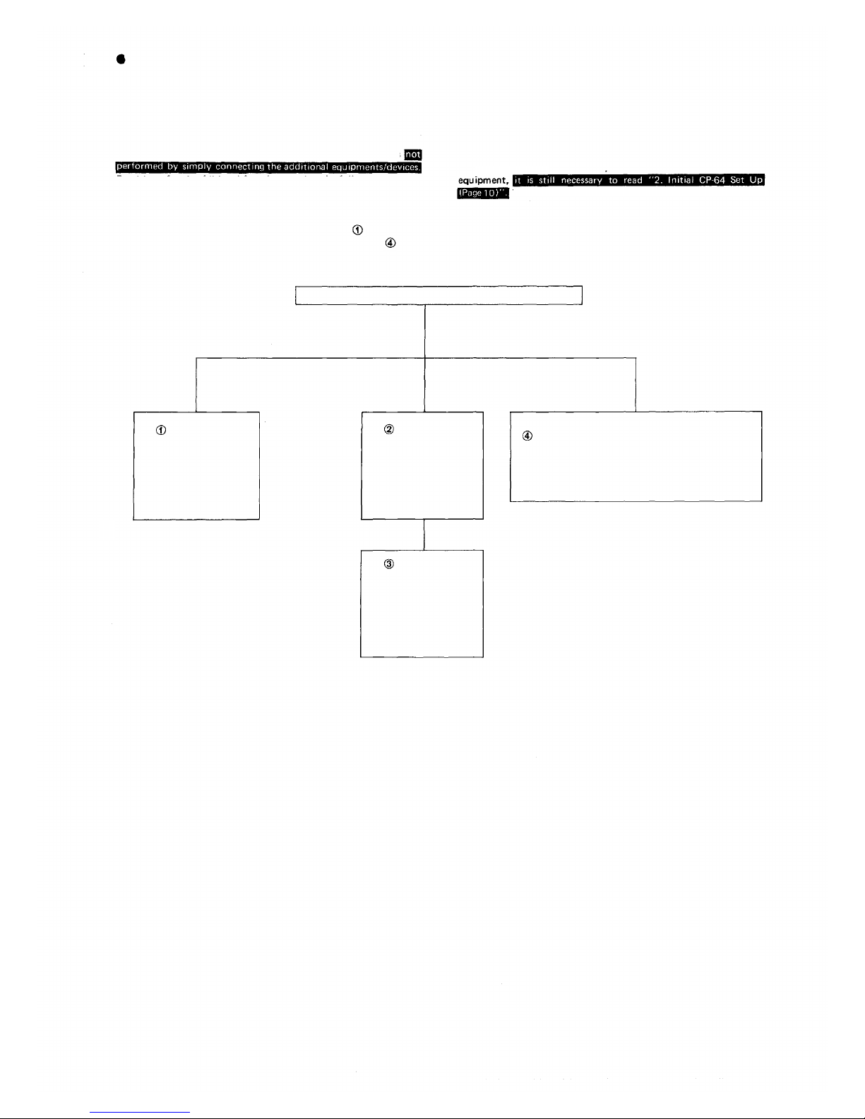
You may add the CP-64 to your TOA INTERCOM SYSTEM EXES6000, according to your specific needs, to obtai n vari ous other
functions. Correct operation of these additional functions is
Provision of such additional function requires the following:
(1) Connection of the additional equipment, as required.
(2) Selec tion o f f uncti on s wh ich s at isfy your needs and setting up
these functions in the respective equipment.
For (1) Connections of Equipment, etc., refer to " Instal lation
Handbook of Model EX-610/620/630 EXCHANGE" or " Opera-
tion Manual of Data Transmitting and Receiving Units", etc.
INSTALLATION HAND BOOK OF EXES-6000
EXES-6000
EX-610/620/630
INSTALLATION
HAND BOOK
OF EXCHANGE
133-21-117-1
EXES-6000
CP-64
INSTALLATION
HAND BOOK
133-21-119-3
(This Hand Book)
This "Installation Handbook of CP-64" deals principally with (2)
Selection of functions and setting up of respective equipment.
This Handbook also explains the connection method for the EXES-
6000 Tie-line System using the CP-64 and the TI-62 units.
There are certain minimum installa tion requirements to be met even
through you may not need many additional functions or additonal
tions or equipments, it is not necessary to read instruction s on
unrequired functions. Make sure, however, that careful study of the
necessary parts of this booklet should be done before proceeding
further
when you may use only some or the additional func-
.
DATA TRANSMITTING AND RECEIVING UNIT
"DT-E11 OPERATION MANUAL" 133-05-094-1A
"DR-B61 OPERATION MANUAL" 133-05-095-0
EXES-6000
CP-64
INITIAL
CHECKING
SHEET FOR
THE SYSTEM
133-21-121-8
— 2 —
Page 4
PART 1. TIE-LINE SYSTEM
TIE-LINE CONNECTION OF THE EXCHANGES
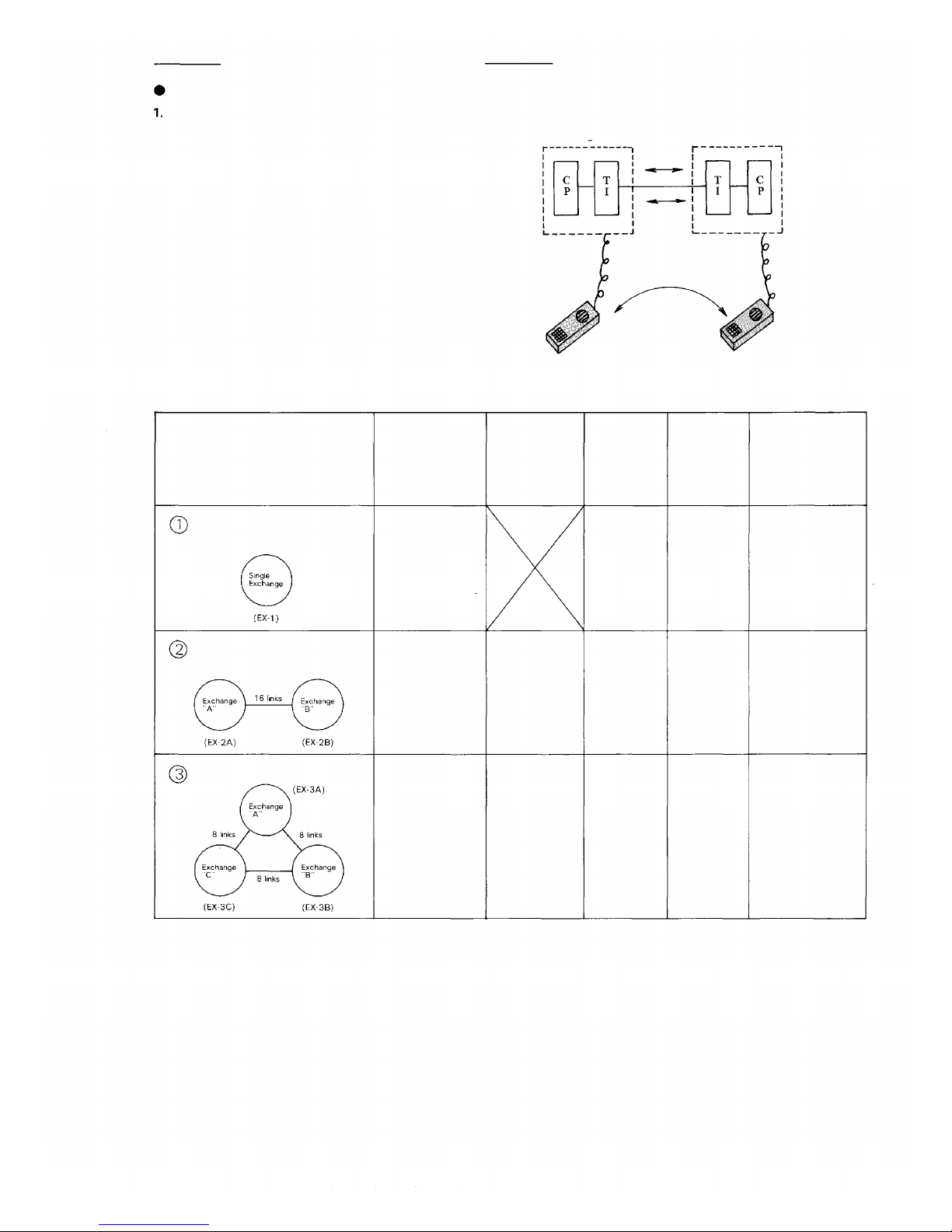
Functions of the Central Processing Unit CP-64 and Tie-line Interface Unit TI-62
To make communications between exchanges possible in the EXES6000 system, the CP-64 and the Tie-line Interface Unit TI-62 are
required in addition to the exchange EX-630.
The TI-62 is the interface unit fo r transmitting and receiving audio
signals and dial data signals between the exchanges.
After receiving dial signals from the station, the CP-64 transmits the
dial data signals to the TI-62 and instructs it to make calls to the
other exchange. The CP-64 also receives the dial data signals from
the other exchange through the TI-62 and calls the station which is
instructed to call by the other exchange.
Overall functions of the system using the Tie-line function are
determined by programming made in the CP-64.
Exchange "A"
Dial
data
Audio
Signal
Call
Exchange "B"
2. Number of stations, paging zones and links
Composition of exchange (s )
Without tie-lines
2 exchanges
3 exchanges
Maximum
number of
links within
own exchange
16
16
*1
Maximum
number of
links between
tielined
exchanges
16
*2
Station
Number of
exchange
1
2
Maximum
number of
stations
256
512
Station
Maximum
number of
paiging zones
All call +31 zones
All call +30 zones
(15 zones/
1 exchange)
*
4
*1 The links within own exchange as well as the tie-line links are used in each tie-line communication.
*2 Each exchange needs one or two Tie-line Interface Unit TI-62.
*3 Each exchange needs two Tie-line Interface units TI-62.
*4 A ll call paging is provided to all the paging zones of all the exchanges connected by tie-line.
16
*1
8 between each
tielined link *3
3
768
All call +45 zones
(15 zones/
1 exchange)
— 3 —
Page 5

3. Numbering schedule for stations and paging zones
Numbering for stations
Type of exchange
Single Exchange (EX-1)
Exchange "A" (EX-2A/3A)
Exchange "B" (EX -2B/3B)
Exchange "C" (EX-3C)
Standard
200~455
470~725
740~995
Without personal number
100~355
*1
400~655
*1
700~955
*1
*1 The first station number of each exchange can be set as any of the following numbers:
100/200/300/400/500/600/700/800/900
*2 No.1 through 8 are employed for Combination Paging.
Numbering for paging zones
All call
0
(00)
00
Zone
1~9 *2
(01-31)
01~15
16~30
31~45
— 4 —
Page 6
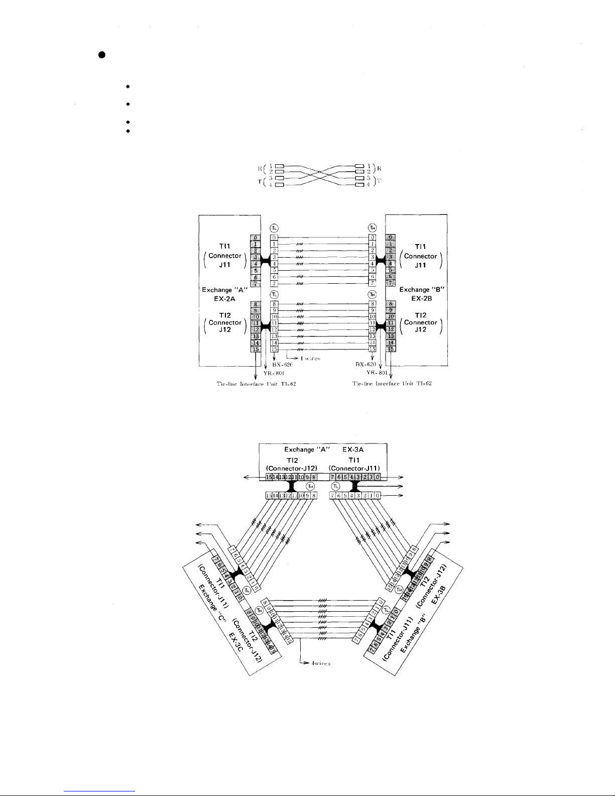
WIRING FOR TIE-LINE CONNECTION OF THE EXCHANGES
Each exchange can be connected by means of a cable with a diameter of 0.65mm (25.6 mil s.) for a distance of up to
2km (5600 ft).
Regarding the tieline links which are not used, turn off the DIP switch of each unused tieline link inside the Tie-line
Unit TI-62.
Connect "T" line (2 wires) of the 4 wires of each link to "R" line (2 wir es) of the other exchange.
The 2 wir es of the "T" line and "R" line have no pola rity.
If the BX-620 is used, its terminals No.1 and 2 are for the "R" line and No.3 and 4 are for t he "T" line.
BX-620
Exchange "A"
1. Wiring for tie-line connection of 2 exchanges
Note 1. Any combination of tie-line links between e xchanges "A" and "B" is possible.
Note 2. Mount only one Tie-line Interface unit when the number of tie -line links is within 8.
2. Wiring for tie-line connection of 3 exchanges
BX-620
Exchange "B"
Tie-line
Interface
BX-620
Tie-line Interface Unit
YR-801
TI-62
Unit
TI-62
Tie-line Interface Unit TI-62
YR-801
BX-620
Note 1. Judging from the front of the exchange, TI-62 (TI1) (connector J11) is the left-hand unit and
TI-62 (TI2) (connector J12) is the right-hand unit.
Note 2. Be sure to connect connector TI 1(J11) to TI2(J12) between the exchanges. Connection of TI1
(J11) to TI1(J11) or TI2(J12) to TI2(J12) will lead to failure of proper operation of the system.
— 5 —
BX-620
YR-801
Tie-lino Interf ace Unit TI-62
Page 7

3. DIP Switch selection
1. Switching arrangements of DIP switches
(E-1, E-2, E-3) in the CP-63 make each
exchange to be of "EX-1" or "EX-2A" or
"EX-2B" or "EX-3A" or "EX-3B" or "EX3C" type. (See "4. CP-64 Dip Switches for
Function Selection" P14)
2. In the event of the tieline link not to be
used, turn off its corresponding DIP switch
on theTI-62 unit.
TI-62 P.C.B.
LINK No.
— 6 —
Page 8
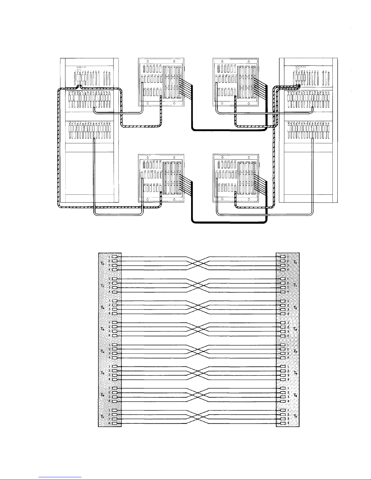
4. The Example of connection of two EX-630 exchanges
"Exchange A" Terminal board (fo r 128 stations) Terminal board (for 128 stations) "Exchange B"
EX-630 BX-620 BX-620 EX-630
YR-801
for Tie-line
YR-810
for stations
"Exchange A"
BX-620 T1
YR-810
for stations
YR-801
for Tie-line
(for 128 stations)
BX-620
YR-810
YR-801
for tie-line
The cables between the
exchanges (4 wires x 8 links)
Terminal board (for 128 stations)
BX-620
The cables between the
exchanges (4 wires x 8 links)
for stations
YR-801
for Tie-line
YR-810
for stations
"Exchange B"
BX-620 T1
— 7 —
Page 9
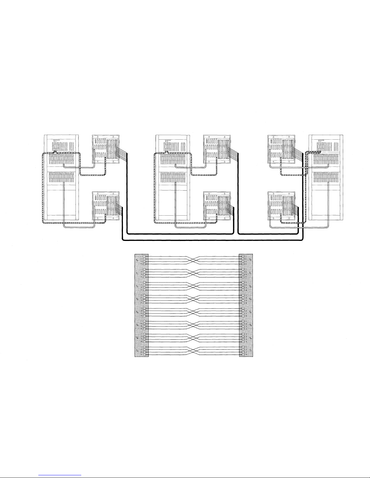
5. T he Example of connection of three EX-630 exchanges
"Exchange A"
EX-630
Terminal board (for 128 stations)
BX-620
"Exchange B"
EX-630
Terminal board (for 128 stations)
BX-620
Terminal board (for 128 stations)
BX-620
YR-810
for stations
YR-801
for Tie-line
YR-801
for Tie-line
Terminal board ( for 128 stations)
BX-620
Terminal board (for 128 stations)
BX-620
"Exchange C"
EX-630
Terminal board (for 128 stations)
BX-620
The cables between the exchanges (4 wires x 8 links)
The cables between the exchanges (4 wires x 8 links)
"Exchange B"
BX-620 T1
The cables between the exchanges (4 wires x 8 links)
YR-810
for stations
YR-801
for Tie-line
"Exchange A"
BX-620 T1
YR-810
for stations
YR-801
for Tie-line
YR-810
for stations
YR-801
for Tie-line
YR-810
for stations
YR-801
for Tie-line
YR-810 for stations
— 8 —
Page 10
PART 2. OPERATING OF CP UNIT AND NO. 200 PROGRAMMING
1. PRECAUTIONS FOR INSTALLATION OF CP-64
Please read following instructions carefully to ensure proper operation of the CP-64
1. Be care ful about damage by static electricity as the CP-64
incorporates CMOS IC's. Do not touch components and connec-
tors.
2. Turn off the AC power switch when you take out or insert the
CP-64 unit, or any other unit.
3. Always insert the CP-64 unit into the "CP" slot. Otherwise,
there is a danger that the unit wi ll be damaged.
4. Make sure mini-jumper for battery back-up is always placed in
ON position each time it is used.
5. Incorrect setting of function select switches may lead to incorrect performance.
6. Even if you do not need programming functions, be sure to carry
out initial programming and registration at station No.200 when
you install the new unit. Otherwise, some other functions may
not work properly.
7. The Ni-Cd battery GB50-3FA1 is capable of saving important
memory registration data even at times of power failure.
To keep the battery fully charged, do not cut the power of f for
long hours during the first 8 days after new installation. The
CP-64 unit is capable of maintaining the programmed data for
the period of 4 weeks after fully charged even in the event of
long hours of power failure.
(About 4 weeks (25° C), About 8 days (40° C) )
8. We suggest you replace the soldered button battery GB50-3FA1
Expected Life Span of small Ni-Cd Battery
Ambient temperature
of exchange
9. When shipping the CP-64 unit independently, place the mini-
(115-42-031-9) with the new one according to the following list
that shows an expected life span of the battery.
Be s ure to make the s tat ion No.200 programming after replacement of the battery.
Ambient temperature
of battery
0°C
25° C
40° C
jumper for battery back-up in "OFF" position. Cover the CP
back with cardboard, wrap connector section in aluminum foil
and put it in a conductive bag.
10°C
35° C
50° C
Life span
About 5 years
About 4 years
About 2 years
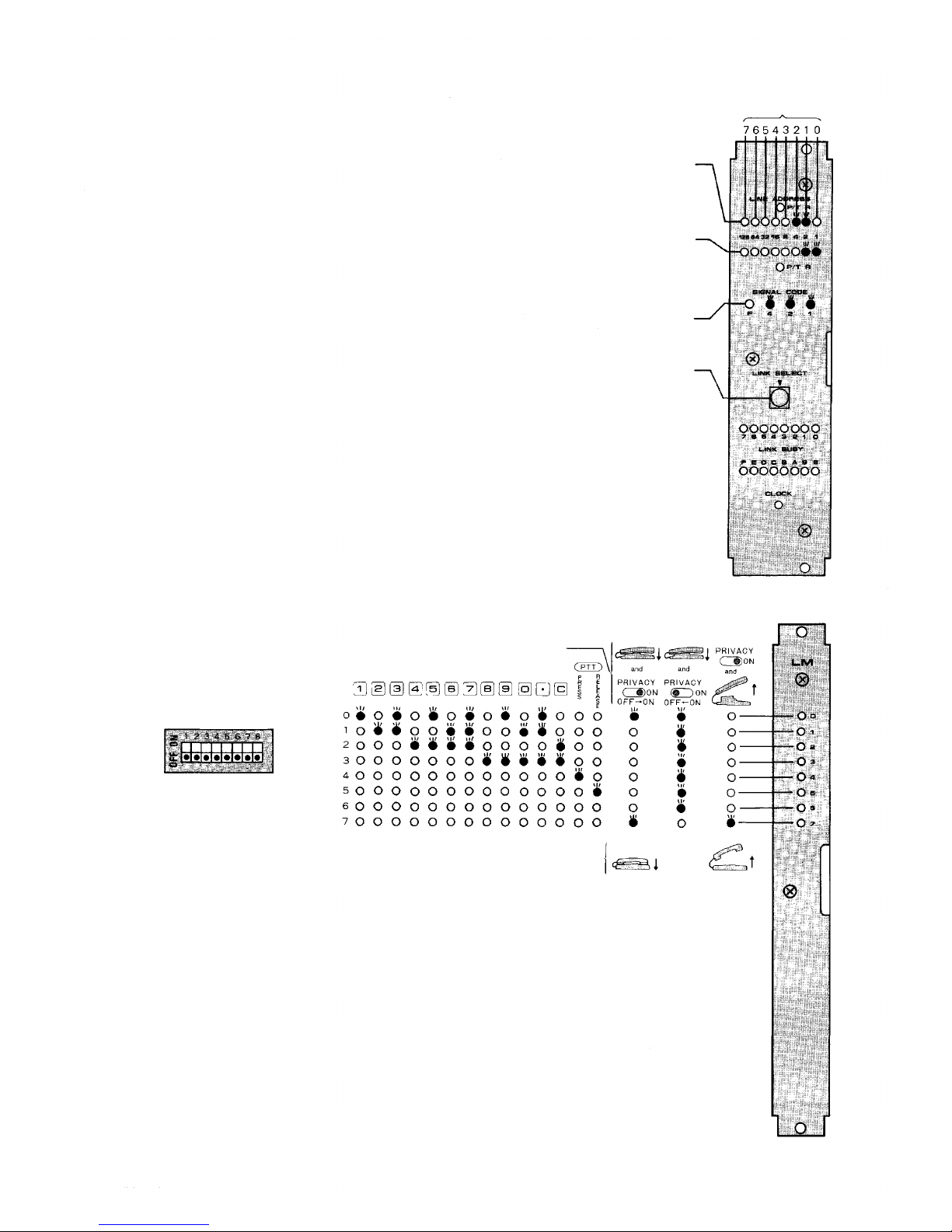
FUNCTION SELECT SWITCHE
SW-E (1~8)
SW-D (1~8)
SW-C
(1~8)
SW-B (1~8)
SW-A (1~8)
PROGRAM SWITC
Set this to"ON"positio
exchange and registratio
is "programming station
is placed in "OFF"
Note:
In the event of the tie-lin
every exchange.
The first station of eac
Exchange
Exchange
Exchange
These
switches select functions.
Link Selectio
H for #200 Programming
position.
"A"
........
"B"
........
"C"
........
S
n
n only at time of initial programming of the
n of functions. In this case, station No.200
" but becomes a normal station when switch
e system, programming has to be set up in
h exchange becomes the Programming station:
No. 200 (100)
. No.470 (400)
. No.740 (700)
MINI-JUMPER for
Ni-Cd BATTERY GB50-3FA
— 9 —
battery back-up
1 (3.6V 50mAh)
Page 11
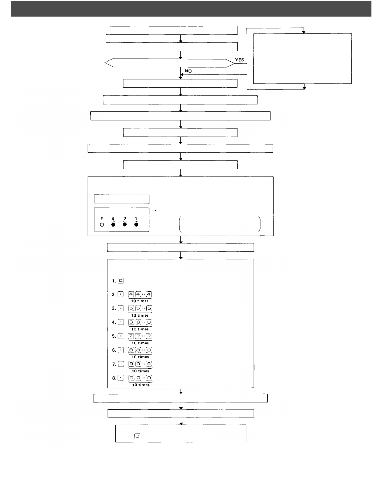
2. INITIAL CP-64 SET UP In the event of the tie line system, programming has to be set up in every exchang
e
Make sure that you have turned off the AC power switch.
Connect the exchange, terminal boards and stations.
Are Data Transmitting and Receiving Units used?
Remove CP-64 from the exchange.
Set mini-Jumper for battery from OFF to ON position.
Set function selection switches (SW-A ~ SW-E) for required functions.
Insert the CP-64 into the exchange.
Set the "LINK SELECT" switches of the HC unit to F (between E and O)
Switch on the exchange.
Look at indication of LINE ADDRESS of HC (20 LEDs) and SIGN AL
CODE indication (4 LEDs)
AL L LED lamps are out
Memory is normal
1. Connect Data Transmitting Unit (DTE11) and Data Receiving Unit (DR-
B61).
2. Set channel select switches (CHANNEL SELECT) of DT-E11.
3. Set word select switches (WORD
SELECT) of DR-B61.
SIG NA L CODE indication
Place program switch on front panel of the CP in "ON" position.
Dial operation from station No. 200. *1
— Initial programming of the exchange —
Dial the Following:
Dial tone will be heard
(Station No. 200 (100) becomes a programming station)
Some errors in memory
Confirmation tone will be heard. *2
(Clears function group S)
Confirmation tone will be heard. *2
(Clears function group A)
Confirmation tone will be heard. *2
(Clears function group B)
Confirmation tone will be heard *2
(Clears function group C)
Confirmation tone will be heard. *2
(Clears function group D)
Confirmation tone will be heard. *2
(Clears function group E)
Confirmation tone will be heard. *2
(Clears personal numbers, single digit dial
numbers and remote numbers)
Lighted lamps of LINE ADDRESS
LEDs indicate erroneous MEMORY
ICs. See Section 3 (Page 11)
Note:
*1; The first station of each ex -
change becomes the prog ram-
ming station:
Exchange "A" ... No. 200 (100)
Exchange "B" ... No. 470 (400)
Exchange "C" ... No. 740 (700)
*2; lf there is any error in CMOS
memory, you hear calling tone
instead of confirmation tone.
Program necessary functions (Refer to separate instructions for each function) *2
Place program switch on front panel of the CP in "OFF" position.
Dial operation from station No. 200. *1
(Station No. 200 becomes a normal station.)
— 10 —
Page 12
3. TROUBLE SHOOTING
3-1 Check of ROM & NMOS-RAM - No calls on the system.
1. Set the "LINK SELECT" switches of the HC to F (between E and O)
and sw itch on the A C power of the exchange.
2. If there is no error, the indication lamps will not light.
3. In the event of a memory error, the lamps may light as shown in the example
of
Fig.
4. The error indications wil l remain on until you use Link No. 15 for com-
1.
munications.
3-2 Confirming of the CP normal working
If the CP, OC and HC are working normally, the HC's indication lamps of LINE
BUSY, LINE ADDRESS and SIGNAL CODE go out.
When any of the lamps lies alight, it is possible that any of the CP, OC or HC is
faulty.
Check first that the CLOCK lamp of the HC is lighting, then confirm that the
CP is working normally by hearing the clicking sound of the PI unit's relay which
is produced when the relay is activated through dial operation of the paging.
If the CP is found working normally, chances are that the HC is faulty, followed
by the OC.
3-3 Check of CMOS-RAM (Programmed data memory)
You hear calling tone instead of confirmation tone, if there is CMOS memory
error at the time of initial programming and registration using station No. 200,
or at the time of registration to Single Digit Number or Personal Number or
Remote Number.
3-4 Dial receiving test
1.
Instead
of the
PI-62
unit,
use the
PIU-52A
(a
unit
used
in the
System) to check the dial receiving section of the CP also to check if the
signal is correctly transmitted as dialed from the station to be tested.
2. If you place all "L INK SELECT" switches (1 ~ 4) of SW-A on the CP-64 in
"OFF" position, conversation is impossible but the dial code from each
station is indicated on the LED's of the PIU as dialed. Use this to find the
cause of any fault of receiving dial information.
3. With use of the PI-62 unit fitted
with no LED, you can also
check that the CP receives the
dial signal by hearing the click
sound of the relay produced
when it is activated.
EXES-5000
Example of
Hands-free/Handset Station
(HF-600M/S)
Example
No.1 (M2)
out of the ROMs (2764)
have "read" error.
No. 0
out of the C-MOS RAMs
(6264) have "read" error.
LINK SELECT Switches set
to select No. 15
and
No.2 (M3)
(M4)
and
No.1 ( M5)
Indicate memory error.
Error ROM - RAM Chip No.
Fig.
1
Fig. 2 DIP switches
(SW-A
of the CP)
3-5 The
order
of
link
usage.
After power is on, links are used in numerical order for each communication.
Remember this to help you when problems are found with specific links.
Remarks:
1. Be sure to avoid mistake at the time of DIP switch installation and No. 200
Programming since such mistake may lead to trouble later.
2. Be sure to make "No. 200 Programming" after "Programming Data Table"
(attached to this manual) is filled out. Keep the finished "Programming Data
Table" (Initial Checking Sheet fo r the System 133-21-121-8) as a part of
complete drawings for each installation.
— 11 —
Example of
Handset Station
(TL-600M/S)
Fig. 3 Dial code indication
PIU-52A unit
Page 13
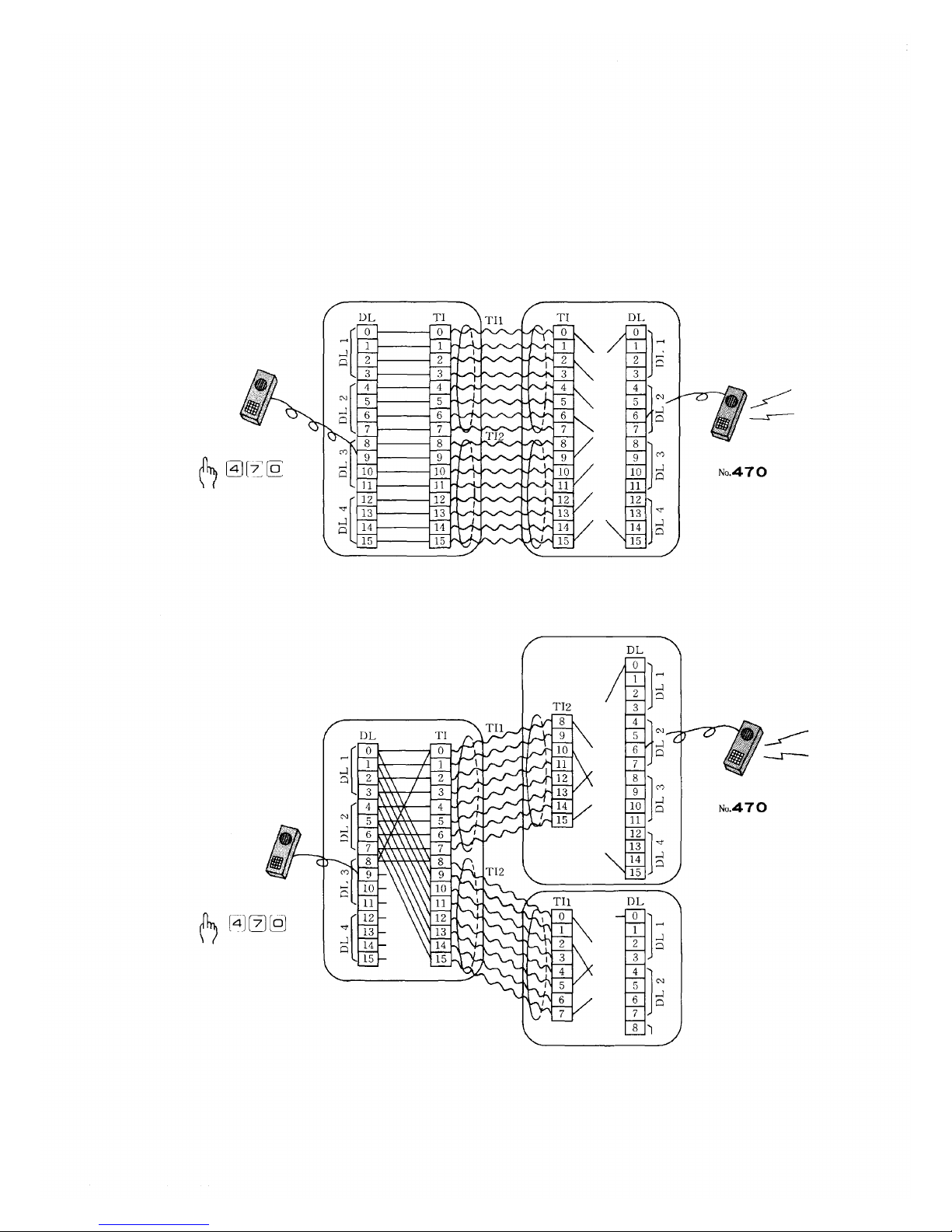
3-6 The order of Tie-line link usage
The Tie-line Link Number which is used in calls between exchanges
is not directly indicated, but you can possibly get it from the link
numbe r which is ind ica ted on the HC-64.
When one Tie-line Link brings up some problems which cause the
system not to work properly, try to find which link number is
causing the problems f rom the indication on the HC-64 of the
exchange making the call.
1. Tie-line for 2 exchanges
Exchange which calls
Station which calls
As Fig. 1 and Fig. 2 show, in the exchanges which make calls, the
DL Link Number corresponds with Tl Tie-line Link Number.
In the exchange which is called, the Tie-line Link Number of the Tl
Unit is fixed by connection between exchanges.
DL Links are used in numerical order.
Exchange which is called
Station which is called
2. Tie-line for 3 exchanges
Station which calls
Exchange which calls
Fig.
1
Exchange which is called
Station which is called
Fig.
— 12 —
2
Page 14
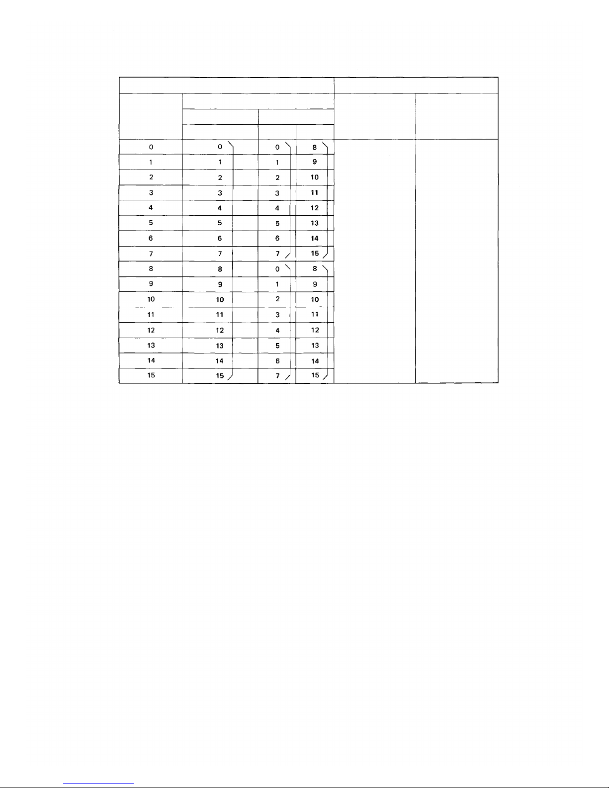
Reference for Connection Link Number between DL and Tl Link
DL
Link No
Exchange which calls
Tl Tie-line Link Number
2 Tie-lines
To TI1,TI2
To TI1
3 Tie-lines
Exchange which is called
Tl Tie-line
Link Number
To
TI2
Fixed by Connection
Cable between
Exchanges
DL Link Number
After power switch
is on, Links are
used in numerical
order
Note.
If the Tl Tie-line Link which corresponds with the DL Link No. is already busy, then,
the next Tie-line Link is automatically used.
— 13 —
Page 15
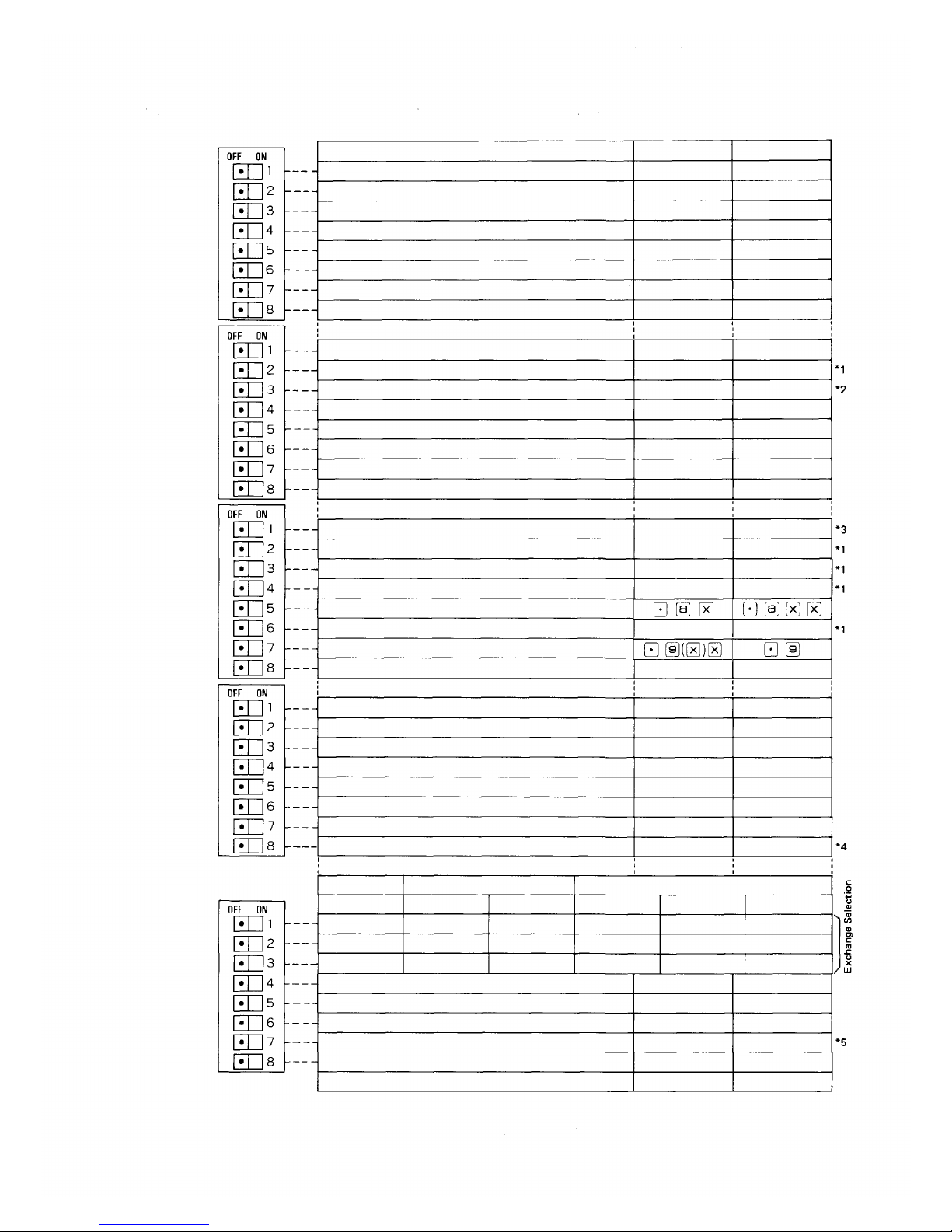
4. CP-64 DIP SWITCHES FOR FUNCTION SELECTION
SW-A
SW-B
SW-C
Functions
Link Selection; Link No. 0 ~ 3
Link Selection; Link No. 4~ 7
Link Selection; Link No. 8 ~ 1 1
Link Selection; Link No. 12 ~ 15
Not Activate
Not Activate
Press-to-talk Control
Not Activate
Conference
Call Transfer, Paging During Normal Call
Priority, Executive Priority/Highest Executive Priority
Priority Selection Executive/Highest Executive
Secretary Transfer, Group Hunting
Not Activate
Pager
Not Activate
Paging
Emergency All-Call
Paging Priority
Combination Paging
Selectable Dial Operation for Paging
Selection of Personal Number Calling/Paging
Selectable Dial Operation for Paging Response
Time Interval Adjustment before Paging Pre-announcement
tone
Switch OFF
Not Activate
Not Activate
Not Activate
Not Activate
(OFF)
(OFF)
Not Activate
(OFF)
Not Activate
Not Activate
Not Activate
Exective Priority
Not Activate
(OFF)
Not Activate
(OFF)
Not Activate
Not Activate
Not Activate
Not Activate
Calling
None
Switch ON
Activate
Activate
Activate
Activate
——
——
Activate
——
Activate
Activate
Activate
Highest Executive
Priority
Activate
——
Activate
——
Activate
Activate
Activate
Activate
paging
1 sec
SW-D
SW-E
Stations Allowed Access to All Call, Conference
and General Purpose Control
Call Forwarding
Not Activate
Group Blocking
Programmable Station Numbering
Not Activate
General Purpose Control
Output Capacity of General Purpose Control
1 x Exchange
EX-1
OFF
OFF
OFF
2 x Exchange
EX -2 A
OFF
ON
OFF
EX-2B
OFF
OFF
ON
Memory of Calling Party Indication (Lamp t ype)
Tone of called Mode at Privacy Sw. ON
Continuous Calling To ne (No. 200 Programming)
Selectable First Station Number
Not Activate
Functions
EX-3A
ON
ON
OFF
Not Activate
Not Activate
(OFF)
Not Activate
Not Activate
(OFF)
Not Activate
Small
3 x Exchange
EX-3B
ON
OFF
ON
Without memory
Privacy
Not Activate
No. 200~
(OFF)
Switch OFF
Activate
Activate
——
Activate
Activate
——
Activate
Large
EX-3C
ON
ON
ON
With memory
Continuous calling
Activate
Programming
——
Switch ON
— 14 —
Page 16

Note: CP DIP SWITCHES FOR FUNCTION SELECTION
*1 Be sure to place the SW-C-1 (Paging) switch in the ON position when paging and its allied
functions are used.
*2 To perform the "Highest Executive Priority" function in Tie-line system, place this switch of
each exchange in the ON position.
*3 Turn on this switch of each exchange even if not all the exchanges require paging function in
Tie-line system. Otherwise, the exchange with this switch off can not perform all-call paging.
*4 Selection of "Large" adds 1 more digit to the number operated.
Example:
*5 Standard (SW-E-7 OFF):
Exchange
Hardwired station number
Programming (SW-E- 7 ON):
The first station number of each exchange in order of the exchanges. A, B and C can be set as
any of the following numbers:
100/200/300/400/500/600/700/800/900
(Hardwired station number)
For the personal number call, use the station number of 100s.
A
200~455
B
470~725C740~995
— 15 —
Page 17
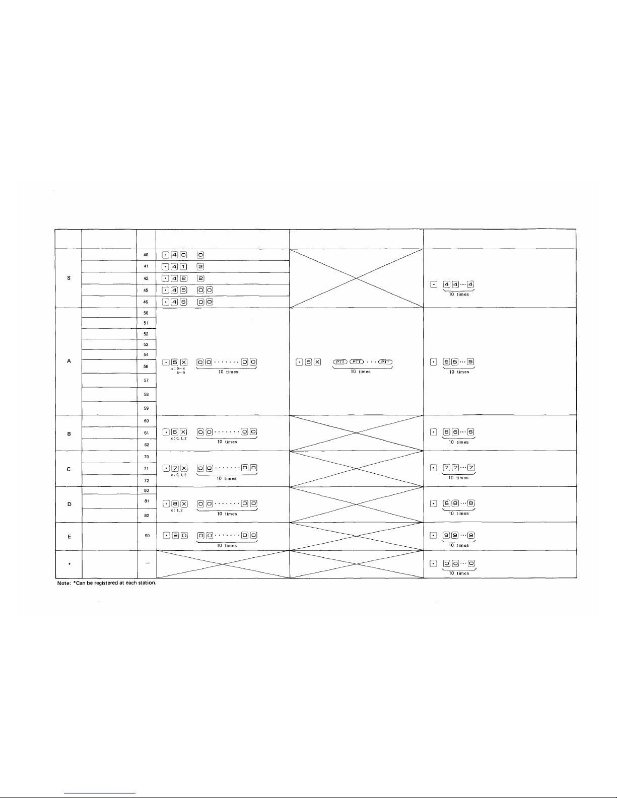
5. FUNCTION CODE TABLE FOR STATION NO. 200 PROGRAMMING
A. Clearance at one time
Function
Group
Function
Function
Code
Clearance of Function
Function Registration on All Stations
Clearance of Function by Function Group
Numbering schedules
of Tie-line system
Selection of Calling
Tone
Selection of Paging
Pre-announcement Tone
Time-out of
Conversation
Time-o ut of Paging
Call
Executive Priority
Continuous Calling
Tone
Station Allowed
Access to All Call
Stations Allowed
Access to Conference
Automatic Access to
Paging
Stations Allowed
Access to One Shot
Make Output
Stations Allowed
Access to Make/
Brake Output
Stations Allowed
Access to 8 Selectable/
Decimal Output
Stations Allowed
Access to 4 Decimal
Digits Output
Secretary Transfer
Master/Sub
Group Hunting
Paging Response,
Paging Priori ty
Group Blocking of
Each Group
Group of Calling
Party Indication
Combination Paging
Group Blocking:
Allowing Calls
Among Groups
Group Blocking:
Allowing Access
to Paging Zones
Programable Station
Numbering
Personal Number
Single Digit Dialing
Remote Response
Confirmation
tone
Confirmation
tone
Confirmation
tone
Confirmation
tone
Confirmation
tone
Confirmation
tone
Confirmation
tone
Confirmation
tone
Confirmation
tone
Confirmation
tone
Confirmation
tone
(Clears function group S)
Confirmation
tone
Confirmation
tone
(Clears function group A)
Confirmation
tone
(Clears function group B )
Confirmation
tone
(Clears function group C)
Confirmation
tone
(Clears function group D)
Confirmation
tone
(Clears function group E)
Confir-
mation
tone
(Clears functions of Personal
No., Single Digit Dialing and
Remote Response)
— 16 —
Page 18
FUNCTION CODE TABLE FOR STATION NO. 200 PROGRAMMING
B. Programming of System
Function
Group
Function
Function
Code
Remarks
Operating for Programming
Initially
Programmed
Mode
Numbering Schedules
of Tie-line System
Selectable first station
number of e ach
exchange
The fol lowing standard station numbering
schedules of the exchanges A, B and C ar e
obtainable. (Hardwired station number)
SW-E-7
OFF
ON
A
200~455
200~455
B
470~725
500~755
C
740~995
800~999
The first station number of each exchange in
order of the exchanges, A, B and C can be set as
any of the following numbers:
100/200/300/400/500/600/700/800/900
(Hardwired station number)
Selection of Calling Tone
Selection of Paging
Pre-announcement
Tone Duration
Time-out Conversation
Time-out Paging Call
Two different calling tones, single note tone or
trill
note
tone,
are
available
in
selection
for
the Hands-free system except the continuous
calling tone.
You can select the length of t ime of paging
pre-announcement tone.
Programming is possible so that stations can be
disconnected automatically f rom the speech
path in t he unit of Minut e and the Hurry-up
Signal Ton e can be heard 10 seconds before the
disconnection.
Programming is possible so that stations can be
disconnected au tomati cally from the Paging
circuit in the unit of Minute and the Hurry-up
Signal Tone can be heard 10 seconds before the
disconnection.
Standard
Station
Numbering
A/B/C=
200/470/740
(SW-E-7 OFF)
or
A/B/C=
200/500/800
(SW-E-7 ON)
Trill note Tone
(0.3
sec.)
Paging
Pre-announce-
ment Tone
(2
sec.)
Without
Time-out
Without
Time-out
First Station No.
of Exchange "A"
1~ 9 (F irst digit)
First Station No.
of Exchange "B"
2~ 9 (First digit)
First Station No.
of Exchange "C"
3~ 9 (First digit)
0: Without Calling Tone
1: Single Note Tone (0.2 sec.)
2: Trill note Tone (0.3 sec.)
0: Without Paging pre-announcement Tone
1: Paging Pre-announcement Tone (1 sec.)
2: Paging Pre-announcement Tone (2 sec.)
00: Without Time-out function
01~99: Length limited (minute)
00: Without Time-out function
01~99: Length limited (minute)
— 17 —
Page 19
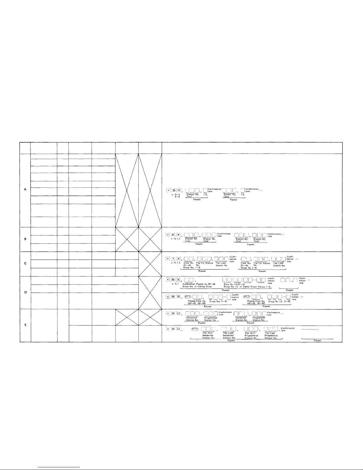
FUNCTION CODE TABLE FOR STATION NO. 200 PROGRAMMING
C. Programming of each Function
Function
Executive Priority
Continuous Calling
Tone
Station Allowed
Access to All Call
Stations Allowed
Access to
Conference
Automatic Access to
Paging
Stations Allowed
Access to One Shot
Make Output
Stations Allowed
Access to Make/
Break Output
Stations Allowed
Access
to 8 Selectable
(One Shot Make)/
Decimal Output
Stations Allowed
Access to 4
Decimal Digit s
Output
Secretary Transfer
Master/Sub
Group Hunting
Paging Zone
Group Blocking:
Establishment of
Each Group
Group of Calling
Party Indication
Function
Code
50
51
52
53
54
56
57
58
59
60
61
62
70
71
72
1st Parameter
Station No.
Station No.
Station No.
Station No.
Station No.
Station No.
Station No.
Station No.
Station No.
Executive
Station No.
Sub Station No.
Main station No.
Zone No. (01~15)
Group No. (1~8)
Group No. (1~8)
2nd Parameter
ON/OFF (1/0)
ON/OFF (1/0)
ON/OFF (1/0)
ON/OFF (1/0)
ON/OFF (1/0)
ON/OFF (1/0)
ON/OFF (1/0)
ON/OFF (1/0)
ON/OFF (1/0)
Secretary Station
No.
Master Station No.
Transfered Station
No.
The First Station
No. of the Zone
The First Station
No. of the Group
The First Station
No. of the Group
The Last Station
No. of the Zone
The Last Station
No. of the Group
The Last Station
No. of the Group
Combination Paging
Group Blocking:
Allowing Calls
Among Groups
Group Blocking:
Allowing Access
to Paging Zones
80
81
82
Combination
Zone No. (90~99)
Calling Group No.
(1~8)
Paging Zone No. of
Paged Group
(00~15, 90~99)
Zone No. (s) (01 ~ 31) (Plural)
Called Group No.(s) (1~8)
(Plural)
Paging G roup No.(s) (1~8)
(Plural)
Programable
Station Numbering
90
Hardwired Station
No.
*2
The First
Hardwired
Station No.
*1
Programmed Sta-
tion No.
*2
The Last
Hardwired
Station No.
*1
The First
Programmed
Station No.
*2
The Last
Programmed
Station No.
*2
*1 Statio n No.'s except Programmed Station No.'s are Hardwired Station No.'s No.100~/200~/300~/400~/470~/500~/600~/700~/740~/800~/900~.
*2 Programmed Station No.'s ar e No.200~999/No.100~999
3rd Parameter
4th Parameter
OPERATING FOR PROGRAMMING
Function
Group
—18—
Page 20
6. STATION NO. 200 PROGRAMMING FOR EACH FUNCTION
6-1 EXECUTIVE PRIORITY (HIGHEST EXECUTIVE PRIORITY) • (FUNCTION C OD E 5 0)
EXECUTIVE PRIORITY (HIGHEST EXECUTIVE PRIORITY)
STEP 1
Touch
Function Code
New Registration?
Executive Station No.
Touch
Executive Station No.
Touch
Confirmation tone
New Registration finished?
NOTES
1. To allow all the stations to have this function.
Touch
10 times
Be s ure to depress the
2. To
release
stations for this function,
Touch
at one
time
key steadily.
the
data programmed
10 times
(Confirmation tone
will be heard.)
Executive Station No.
Touch
Executive Station No.
Touch
Confirmation tone
(Confirmation tone
will be heard.)
into
all the
Release?
Release finished?
Return
3. Re-start at Step 1 when mis-dialing occurs.
(All other registrations remain valid.)
4. CP DIP switch B-3 must be "ON" to employ this function.
* Executive Station: Executive or Highest Executive Sta-
tion.
— 19 —
Page 21

6-2 CONTINUOUS CALLING TONE (FUNCTION CODE 51)
CONTINUOUS CALLING TONE
STEP 1
Touch
Function Code
New Registration?
Continuously Called Station No. ON
Touch
Continuously Called Station No. ON
Touch
Confirmation tone
New Registration finished?
Release?
NOTES
1. To allow all the stations to have this function.
Touch
Be sure to depress the
2. To
release
stations for this function,
Touch
at one
time
10 times
key steadily.
the
data programmed
10 times
(Confirmation tone
will be heard.)
Continuously Called Station No. O FF
Touch
Continuously Called Station No. OFF
Touch
Confirmation tone
Release finished?
Return
3. Re-start at Step 1 when mis-dialing occurs.
(Confirmation tone
will be heard.)
into
all the
(All other registrations remain valid.)
4. CP DIP switch E-6 must be "ON" to employ this function.
— 20 —
Page 22

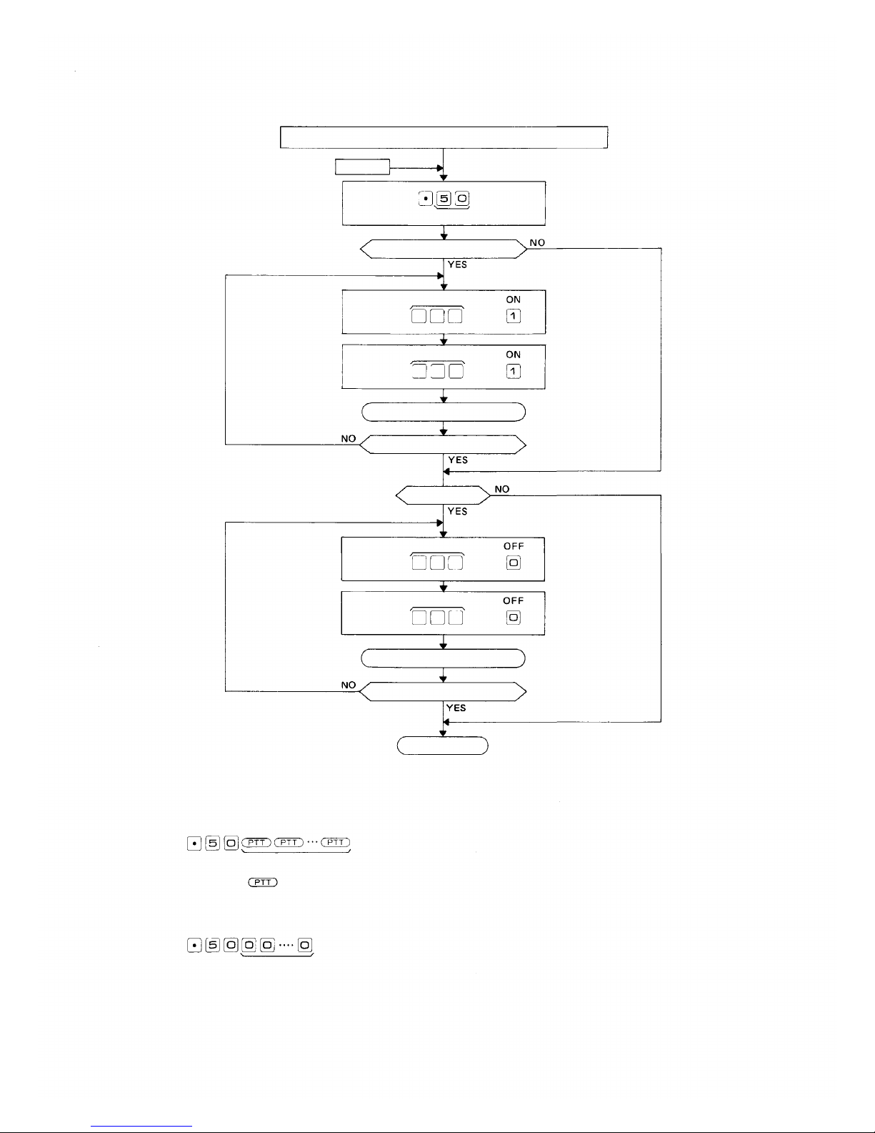
6-3 STATIONS ALLOWED ACCESS TO ALL CALL (FUNCTION CODE 52)
STATIONS ALLOWED ACCESS TO ALL CALL
STEP 1
Touch
Function Code
New Registration?
Allowed Station No.
Touch
Allowed Station No.
Touch
Confirmation tone
New Registration finished?
Release?
Allowed Station No.
Touch
Allowed Station No.
Touch
Confirmation tone
Release finished?
ON
ON
OFF
OFF
NOTES
1. To allow all the stations to have this function.
Touch
Be sure to depress the
10 times
key steadily.
2. To release at one time the data programmed into all the
stations for this function.
Touch
10 times
(Confirmation tone
will be heard.)
Return
(Confirmation tone
will be heard.)
3. Re-start at Step 1 when mis-dialing occurs.
(All other registrations remain valid.)
4. Programming is necess ary only if CP DIP switch D-1 is "ON".
— 21 —
Page 23

6-4 STATIONS ALLOWED ACCESS TO CONFERENCE (FUNCTION CODE 53)
STATIONS ALLOWED ACCESS TO CONFERENCE
STEP 1
Touch
Function Code
New Registration?
Allowed Station No.
Touch
Allowed Station No.
Touch
Confirmation tone
New Registration finished?
Release?
NOTES
1. To allow all the stations to have this function.
Touch
Be sure to depress the
2. To
release
stations for this function.
Touch
at one
time
10 times
key steadily.
the
data programmed
10 times
(Confirmation tone
wil l be heard.)
Allowed Station No.
Touch
Allowed Station No.
Touch
Confirmation tone
Release finished?
(Confirmation tone
wil l be heard.)
into
all the
OFF
OFF
Return
3. Re-start at Step 1 when mis-dialing occurs.
(All other registrations remain valid.)
4. Programming is necessary only if CP DIP switch D-1 is "ON".
Switch B-1 must be "ON" to employ this function.
— 22 —
Page 24

6-5 AUTOMATIC ACCESS TO PAGING (FUNCTION CODE 54)
HANDSET SUBSTATIONS ALLOWED ACCESS TO PAGING
STEP 1
Touch
Function Code
New Registration?
Allowed Station No.
Touch
Allowed Station No.
Touch
Confirmation tone
New Registration finished?
Release?
Touch
Touch
NOTES
1. To allow all the stations to have this function.
Touch
Be sure to depress the
2. To release at one time the data programmed into all t he
stations for this function.
Touch
key steadily.
10 times
(Confirmation tone
will be heard.)
(Confirmation tone
will be heard.)
Allowed Station No.
Allowed Station No.
Confirmation tone
Release finished?
Return
3. Re-start at Step 1 when mis-dialing occurs.
OFF
OFF
(All other registrations remain valid.)
— 23 —
Page 25

COMPLEMENTARY NOTES
(1) Automatic Access to Paging
This function facilitates Paging / Paging response f rom a
Substation TL-600S. Just picking up the Handset of Substa tio n a uto maticall y act ivates Paging or Paging Response
mode.
(2) Required Programming for Automatic Access to Paging
from Handset Substation.
2-1) First, connect a Master Station HF-600M or TL-600M in place
of a Substation TL-600S.
2-2) Program at that station a necessary function for Single Digit
Dialing such as Paging, Paging Response, Personal Number Call
or
etc.
2-3) Then, replace the Master Station with a Substation TL-600S.
2-4) Program "Automatic Access to Paging fro m Handset Substation
(Function Code 54)" at the Station No. 200 according to the
programming instructions.
(5) Call by Dialing & Picking up the Handset
Function
Singl e Digit
Dialing
Necessary
Programming
Single Digit
Registration
at Station
By dialing
at
HF-620S or
HF-600S
(3) Single Digit Dialing and Automatic Access to Paging
By programming "Single Digit Dialing" at any master station, a
single touch of the dial activates "Station Call", "Personal
Number Call", "Paging" or "Paging Response" mode. But in
using a TL-600S and a HF-600S, "Automatic Access to Paging
from Handset Substation" function cannot be adopted only by
programming "Single Digit Dialing" at the station. It also
requires the programming f or Function Code 54 at No. 200
Station.
(4) A call to Master Station from Handset or Hands-free/
Handset Substation
"Master/Sub Relationship (Function Code 61)" can be
programmed into Handset Substation TL-600S or Hands-free/
Handset Substation HF-600S etc., where you can call the
relative Master Station by a single touch of the dial , or by
picking up the Handset.
In activating a mode with Hands-free/Handset Substation
HF-600S by picking up the Handset, "Privacy" switch on the
Station is to be "ON" position.
Call to Master Station
By picking up
Handset
at
TL-600S or
HF-600S
(Privacy SW. ON)
Paging Call, Paging Response
or Pers onal Number Ca ll
By dialing
at
HF-620S or
HF-600S
By picking up
Handset
at
TL-600S or
HF-600S
(Privacy SW. ON)
Master/sub
Relationship
Automatic Acess to Paging
Paging (or Calling)
from Handset Substation
*1
Programming at
Station No. 200
(Function Code 61)
1. Single Digit
Registration
at Station
2. Programming at
Stati on No.200
(Function Code 54)
: Possible
: Impossible
: Possible but usually Not to be used
: Possible across the tie-lined exchange.
: Impossible across the tie-lined exchange.
— 24 —
Page 26

6-6 STATIONS ALLOWED ACCESS TO ONE-SHOT MAKE OUTPUT (FUNCTION CODE 56)
STATION ALLOWED ACCESS TO ONE SHOT MAK E OUTPUT
STEP 1
Touch
Function Code
New Registration?
Allowed Station No.
Allowed Station No.
Confirmation tone
New Registration finished?
Release?
Allowed Station No.
Allowed Station No.
Confirmation tone
Release finished?
Return
NOTES
1. To allow all the stations to have this function. 3. Re-start at Step 1 when mis-dialing occurs.
Touch
10 times
Be s ure to depress the
2. To release at one time the data programmed into all th e
stations for this function.
Touch
key steadily.
10 times
(Confirmation tone
will be heard.)
(Confirmation tone
will be heard.)
(All other registrations remain valid.)
4. Programming is necessary only if CP DIP switch D-1 is "ON".
— 25 —
Page 27

6-7 STATIONS ALLOWED ACCESS TO MAKE/BREAK OUTPUT (FUNCTION CODE 57)
STATIONS ALLOWED ACCESS TO MAKE/BREAK OUTPUT
STEP 1
Touch
Function Code
New Registration?
Allowed Station No. ON
Touch
Allowed Station No. ON
Touch
Confirmation tone
New Registration finished?
Release?
Touch
Touch
NOTES
1. To allow all the stations to have this function,
Touch
Be sure to depress the
2. To release at one time the data programmed into all the
stations for this function,
Touch
key steadily.
(Confirmation tone
,. . (A ll other registrations remain valid.)
/0
(Confirmation tone
will be heard.)
will be heard.)
Allowed Station No. OFF
Allowed Station No. OFF
Confirmation tone
Release finished?
Return
3. Re-start at Step 1 when mis-dialing occurs.
4. Programming is necessary only if CP DIP switch D-1 is "ON".
— 26 —
Page 28

6-8 STATIONS ALLOWED ACCESS TO 8 SELECTABLE (ONE-SHOT MAKE) OR
DECIMAL OUTPUT (FUNCTION CODE 58)
STATIONS ALLOWED ACCESS TO 8 SELECTABLE
(ONE-SHOT MAKE) OR DECIMAL OUTPUT
STEP 1
Touch
Function Code
New Registration?
Allowed Station No.
Touch
Allowed Station No.
Touch
Confirmation tone
New Registration finished?
Touch
Touch
NOTES
1. To allow all the stations to have this function,
Touch
Be sure to depress the
2. T o release at one time the data programmed into all the
stations for this function,
Touch
key steadily.
(Confirmation tone
wil l be heard.)
(Confirmation tone
wil l be heard.)
Release?
Allowed Station No.
Allowed Station No.
Confirmation tone
Release finished?
Return
3. Re-start at Step 1 when mis-dialing occurs.
(All other registrations remain valid.)
4. Programming is necessary only if CP DIP switch D-1 is "ON".
— 27 —
Page 29

6-9 STATIONS ALLOWED ACCESS TO 4 DECIMAL DIGITS OUTPUT (FUNCTION CODE 59)
STATIONS ALLOWED ACCESS TO 4 DECIMAL DIGITS OUTPUT
STEP 1
Touch
Function Code
New Registration?
Allowed Station No.
Touch
Allowed Station No.
Touch
Confirmation tone
New Registration finished?
Release?
Touch
Touch
1. To allow all the stations to have this function.
Touch
Be sure to depress the
2. To release at one time the data programmed into all the
stations for this function,
Touch
key steadily.
(Confirmation tone
will be heard.)
(Confirmation tone
wil l be heard.)
Allowed Station No.
Allowed Station No.
Confirmation tone
Release finished?
Return
3. Re-start at Step 1 when mis-dialing occurs.
(All other registrations remain valid.)
4. Programming is necessary only if CP DIP switch D-1 is "ON".
— 28 —
Page 30

6-10 SECRETAR Y TRA NSFER (FUNCTION CODE 60)
SECRETARY TRANSFER
Step 1
Touch
Function Code
New Registration?
Executive Station No.
Touch
Executive Station No.
Touch
Executive Station No.
Touch
Executive Station No.
Touch
Secretary Station No.
Secretary Station No.
Confirmation tone
New Registration finished?
Release?
Executive Station No.
Executive Station No.
Confirmation tone
Release finished?
NOTES
1. To release at one time the data programmed into all the
stations for thi s function.
Touch
2. Re-start at Step 1 when mis-dialing occurs.
(All other registrations remain valid.)
(Confirmation tone
wil l be heard.)
Return
3. Switch B-5 must be "ON" to employ this function.
4. Programming of Secretary Transfer can be made in a daisy
chain method. For their examples, refer to the following sketch.
— 29 —
Page 31

6-11 MASTER/SUB RELATIONSHIP (FUNCTION CODE 61)
MASTER/SUB RELATIONSHIP
Step 1
Touch
Function Code
New Registration?
Touch
Touch
Touch
Touch
Sub Station No.
Sub Station No.
Confirmation tone
New Registration finished?
Release?
Sub Station No.
Sub Station No.
Confirmation tone
Release finished?
Master Station No.
Master Station No.
Sub Station No.
Sub Station No.
NOTES
1. To release at one time the data programmed into all the
stations for this function.
Touch
(Confirmation tone
wi ll be heard.)
Return
2. Re-start at Step 1 when mis-dialing occurs.
(All other registrations remain valid.)
— 30 —
Page 32

6-12 GROUP HUNTING (FUNCTION CODE 62)
TRANSFERED STATION No. FOR GROUP HUNTING
Step 1
Touch
Function Code
New Registration?
Original Station No.
Touch
Original Station No.
Touch
Original Station No.
Touch
Original Station No.
Touch
Transferred Statio n No.
Transferred Stat ion No.
Confirmation tone
New Registration finished?
Release?
Original Station No.
Original Station No.
Confirmation tone
Release finished?
NOTES
1. To release at one time the data programmed into all the
stations for this function,
Touch
2. Re-start at Step 1 when mis-dialing occurs.
(Al l other registrations remain valid.)
(Confirmation tone
wil l be heard.)
Return
3. Switch B-5 must be "ON" to employ this function.
4. Programming of Group Hunting can be made in a daisy chain
method. For their examples, refer to the following sketch.
— 31 —
Page 33

6-13 PAGING ZONE (FUNCTION CODE 70)
ESTABLISHMENT OF EACH PAGING ZONE
Step 1
Touch
Paging Zone No. First Station No. Last Station No.
(01~, 16~, 31~) of the Zon e of the Zone
Touch
Paging Zone No. First Station No. Last Station No.
(01 ~,
16~,
Touch
Function Code
31~) of the Zone of the Zone
Confirmation tone
New Registration finished?
NOTES
1. To release at one time the data programmed into all the
Zones for this function.
Touch
(Confirmation t one
will be heard.)
2. Re-start at Step 1 when mis-dialing occurs.
(Al l other registrations remain valid.)
3. Switch C-1 must be "ON" to employ this function.
4. 2-Digit dialing is necessary even in the case of Zone No.1
to
No.9.
Ex. Zone No.2
Return
5. In the
mode
case
"Paging
Response
Without
is selected bv the DIP Switch
SW-C-7, this registration is essential.
6. In the
case
"Paging
DIP Switch SW-C-3, this registration should be made for
Priority"
function
each Paging Zone of No.01 to No.31.
7. Zone number series of each exchange in Tie -line system.
Exchange "A" -----
Exchange
"B"
Exchange "C" -----
No.01~15
----- No.16~30
No.31~45
Zone
is
adopted
Number"
by the
— 32 —
Page 34

6-14 GROUP BLOCKING 1 : ESTABLISHMENT OF EACH GROUP (FUNCTION CODE 71)
GROUP BLOCKING 1
ESTABLISHMENT OF EACH GROUP
Step 1
Touch
Function Code
Group No. First Station No. Last Station No.
(1~8,1~6) of the Group of the Group
Touch
Group No. First Station No. Last Station No.
(1~8,1~6) of the Group of the Group
Touch
Confirmation tone
New Registration finished?
NOTES
1. To release at one time the data programmed into all the
groups for this function,
Touch
2. Re-start at Step 1 when mis-dialing occurs.
(Al l other registrations remain valid.)
(Confirmation tone
will be heard.)
Return
3. CP DIP switch D-4 must be "ON" to employ this function.
4. Group No.
Single exchange ..... No.1~8
Tie-line exchange . . . . . No.1~6
— 33 —
Page 35

6-15 CALLING PARTY INDICATION (LAMP TYPE) (FUNCTION CODE 72)
Registration of station number(s) having indication panel.
ESTABLISHMENT OF EACH GROUP
Step 1
Touch
Function Code
Group No. First Station No. Last Station No.
(1 ~ 8) of the Group of the Group
Touch
Group No. First Station No. Last Station No.
(1 ~ 8) of the Group of the Group
Touch
Confirmation tone
New Registration finished?
NOTES
1. To release at one time the data programmed into all the
groups for this function,
Touch
2. Re- start at Step 1 when mis-dialing occurs.
(A ll other registrations remain valid.)
(Confirmation tone
will be heard.)
Return
3. When the Indication Panel belongs to on ly one (1) station,
you should write the station number in both "First Sta-
tion No." and "Last Station No." columns.
— 34 —
Page 36

6-16 COMBINATION PAGING (FUNCTION CODE 80)
COMBINATION PAGING
Step 1
Touch
Function Code
New Registration?
Combination Paging Paging Zon e No. ( s )
Zone No. (90 ~ 99) (01 ~ 31 ) (01 ~ 31)
Touch
Combination Paging Paging Zone No. (s)
Zone No. (90 ~ 99) (01 ~ 31) (01 ~ 31)
Touch
Confirmation tone
New Registration finished?
Combination Paging Zone No. (90 ~ 99)
Touch
Combination Paging Zone No. (90 ~ 9 9)
Touch
NOTES
1. To release at one time the data programmed into all t he
Zones for this function,
Touch
2. Re-start at Step 1 when mis-dialing occurs.
(Confirmation tone
will be heard.)
(Al l other registrations remain valid.)
Release?
Confirmation tone
Release finished?
Return
3. CP DIP switch C-1 and C-4 must be "ON" to employ this
function.
— 35—
Page 37

6-17 GROUP BLOCKING 2 : ALLOWING CALLS AMONG GROUPS (FUNCTION CODE 81)
GROUP BLOCKING 2
ALLOWING CALLS AMONG GROUPS
Step 1
Touch
Function Code
New Registration?
Calling Group Called Group
No. (1 ~ 8) No. (s) (1 ~ 8)
Touch
Calling Group Called Group
No. (1
~
8) No. (s) (1 ~ 8)
Touch
Confirmation tone
New Registration finished?
(max.
(max.
7)
7)
Calling Group No. (1 ~ 8)
Touch
Calling Group No. (1 ~ 8)
Touch
NOTES
1. To release at one time the data programmed into all t he
groups for this function,
Touch
2. Re-start at Step 1 when mis-dialing occurs
(All other registrations remain valid.)
(Confirmation tone
wil l be heard.)
Release?
Confirmation tone
Release finished?
Return
3. Do not register a Group to call itself.
4. CP DIP switch D-4 must be "ON" to employ t his function.
— 36—
Page 38

6-18 GROUP BLOCKING 3 : ALLOWING GROUP ACCESS TO PAGING (FUNCTION CODE 82)
GROUP BLOCKING 3
ALLOWING ACCESS TO PAGING ZONES
Step 1
Touch
Function Code
New Registration?
Paging Zone (00 ~ 45) or Paging Group No. (S)
Combination Paging Zone (90 ~ 99) (1 ~ 8, 1 ~ 6) (max . 8 )
Touch
Paging Zone (00 ~ 45) or Paging Group No. (S)
Combination Paging Zone (90 ~ 99) (1 ~ 8, 1 ~ 6) (max . 8)
Touch
Confirmation tone
New Registration finished?
Paging Zone (00 ~ 45) or
Combination Paging Zone (90 ~ 99}
Touch
Paging Zone (00 ~ 4 5) or
Combination Paging Zon e (90 ~ 99)
Touch
NOTES
1. To release at one time the data programmed into all the
groups for this function.
Touch
10 times
2. Re-start at Step 1 when mis-dialing occurs
(Confirmation tone
will be heard.)
(All other registrations remain valid.)
Release?
Confirmation tone
Release finished?
Return
3. CP DIP switch D-4 must be "ON" to employ this function.
4. Group No.
Single
exchange
...... No.1 ~ 8
Tie-line exchange ..... N
o.1 ~ 6
— 37—
Page 39

6-19 PROGRAMMABLE STATION NUMBERING (FUNCTION CODE 90)
A. Programming of Single Station Number
PROGRAMMABLE STATION NUMBERING
Step 1
Touch
Function Code
New Registration?
Hardwired Station No. Programmed Station No.
Touch
Hardwired Station No.
Touch
Confirmation tone
New Registration finished?
Release?
Hardwired Station No. Hardwired Station No.
Touch
Hardwired Station No.
Touch
Confirmation tone
Release finished?
Programmed Station No.
Hardwired Station No.
Return
— 38 —
Page 40

B. Programming of Serial Station Numbers
PROGRAMMABLE STATION NUMBERING
Step 1
Touch
Function Code
New Registration?
First
Hardwired Station No.
First
Hardwired Station No.
First
Hardwired Station No.
First
Hardwired Station No.
Last
Hardwired Station No.
Last
Hardwired Station No.
Confirmation tone
New Registration finished?
Release?
Last
Hardwired Station No.
Last
Hardwired Station No.
Confirmation tone
Release fin ished ?
First
Programmed Station No.
First
Programmed Station No.
First
Hardwired Station No.
First
Hardwired Station No.
Last
Programmed Station No.
Last
Programmed Statio n No.
Last
Hardwired Station No.
Last
Hardwired Station No.
NOTES
1. To release all registered Programmed Station No.'s at one time.
Touch
10 times
C. Restriction of programmable station numbering
Each station number can be programmable in the station number series of the exchanges A, B and C that
have been determined by the function of the "Selectable First Station Number" (Page 17).
Restriction of station numbers (*1) and (*2)
<Example 1> W ith personal number (Standard) <Example 2> Without personal number
Exchange
A
C
Hardwired
Station No.
200~455
B
470~725
740~995
Programmed
Station No.
200~469
470~739
740~999
(Confirmation tone
will be heard.)
Exchange
A
B
C
Return
Hardwired
Station No.
100~355
400~655
700~955
— 39 —
2. Any one Programmed Station No. cannot be assigned to more
than one Hardwired Station.
3. CP DIP switch D-5 must be "ON" to employ this function.
<Example 3>
Programmed
Station No.
100~399
400~699
700~999
Exchange
A
B
C
Hardwired
Station No.
200~455
500~755
800~999
Programmed
Station No.
200~499
500~799
800~999
Page 41

7. PROGRAMMING DATA TABLE
INITIAL PROGRAMMING
Note. (Mark *)
The first station of each exchange becomes the Programming Station:
Exchange
Exchange
Exchange
"A"
.........................
"B"
.........................
"C"
.........................
Initial Programming of the Exchange
1. Place program switch on front panel of the CP "ON"
Dial operation from station No. 200 (100). *
Dial tone will be heard (Station No. 200 (100) becomes a programming station)
No. 200
No. 470
No. 740
(100)
(400)
(700)
Confirmation
Confirmation
Confirmation tone will be heard (Clears function group B)
Confirmation tone will be heard (Clears function group C)
Confirmation tone will be heard (Clears function group D)
Confirmation tone will be heard (Clears function group E)
Confirmation tone will be heard.
(Clears personal numbers, single digit dial numbers and remote numbers)
Program necessary functions.
(Refer to separate instructions for each function)
Place program switch on front panel of the CP in "OFF" position.
(Station No. 200 (100) becomes a normal station.) *
tone
tone
will
will
be
be
heard
heard
(Clears
(Clears
function
function
group
S)
group A)
Clearance of Each Function at a Time
Establishment of Function on All Stations at a Time
Confirmation tone
Confirmation tone
— 40 —
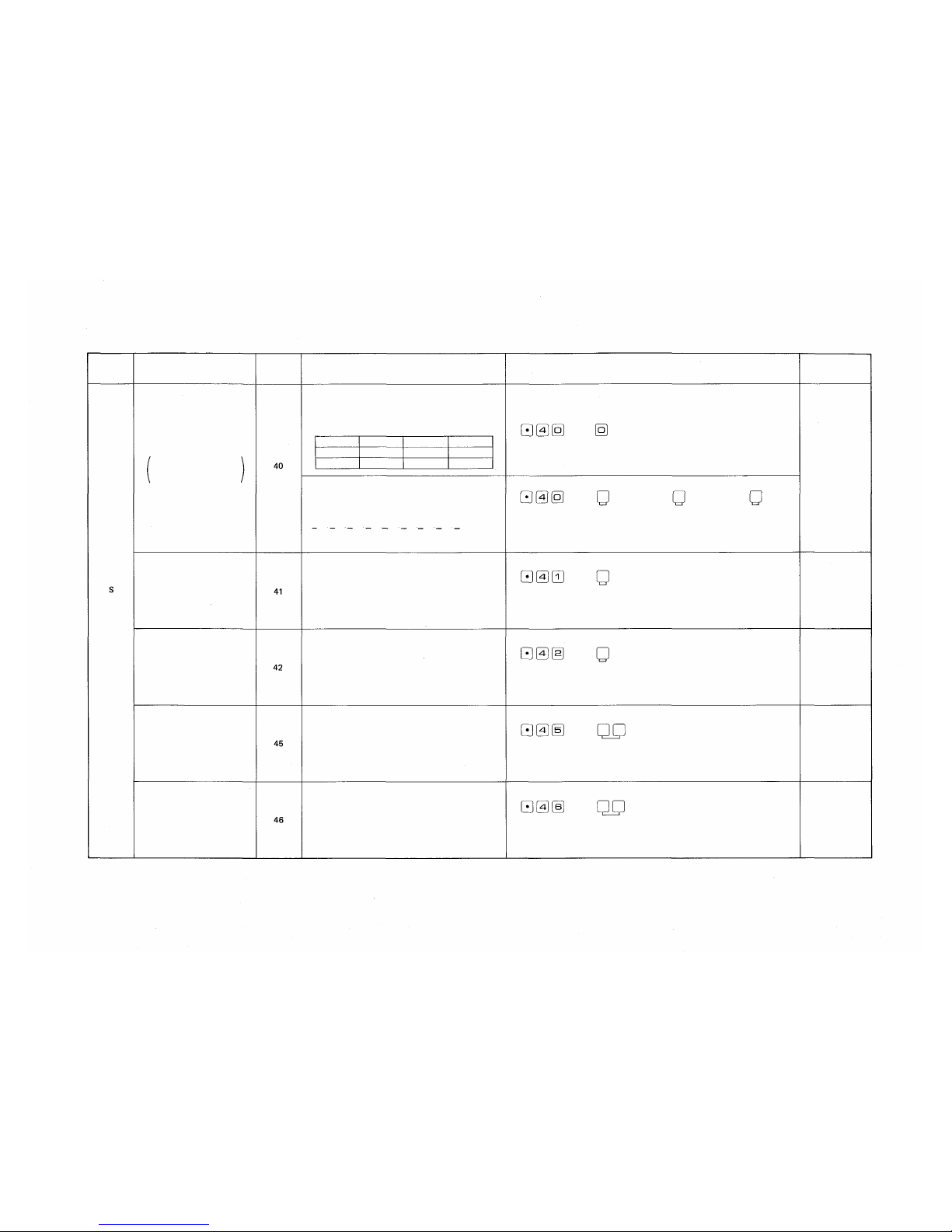
Page 42

Function Table for the System
Function
Group
S
Function
Numbering schedules
of tie- line system
Selection of
Calling Tone
Selection of Paging
Pre-announcement
Tone
Time-out of
conversation
Function
code
40
41
42
45
Registered
data
A
B
C
——
Note of Registration
00
Select the head number of stations
in each exchange from among the
followings:
00
100, 200, 300, 400, 500, 600, 700,
800 or 900
00
0: Without Calling Tone
1: Single tone (0.2 sec.)
2: Calling tone (0.3 sec.)
0: Without Paging
Pre-announcement Tone
1 : Paging Pre-announcement
Tone (1 sec.)
2: Paging Pre-announcement
Tone (2 sec.)
00: Without Time-out function
01 ~ 99: Length limited (min.)
Initial programming
A/B/C=
200/470/740
(SW-E-7 OFF)
200/500/800
(SW-E-7 ON)
1:
Calling Tone
(0.3
sec.)
2:
Paging
Pre-announcement
Tone (2 sec.)
00:
Without Time-out
Time-out of
Paging call
46
00: Without Time-out function
01 ~ 99 : Length limited (min.)
00:
Without Time-out
— 41 —
Page 43

Function Table for Stations
Function Group
Function
Function Code
Name
Hardwired
Station No.
Standard
No.
Without
Personal
No.
Others
Confirmation
of
Conversation
Programmed S tation
No.
Executive Priority
Highest
Executive Priority
Continuous Calling Tone
Stations Allowed Access
to All
Call
Stations
Allowed Access
to
Conference
Automatic
Access
to
Paging
Stations Allowed Access
to One
Shot Output
Stations Allowed Access
to
Make/Break Output
Stations Allowed Access
to 1/8
Select
(or
Decimal)
Output
Stations
Allowed Access
to 4
Decimal
Digits
Output
Secretary
Station
No. *1
Master
Station
No. *1
Transfered
Station
No. for
Group Hunting
*1
*1: Hardwired Station No.
— 42 —
Page 44

PART 3. FUNCTION SELECTION FOR DATA
TRANSMITTING AND RECEIVING UNITS
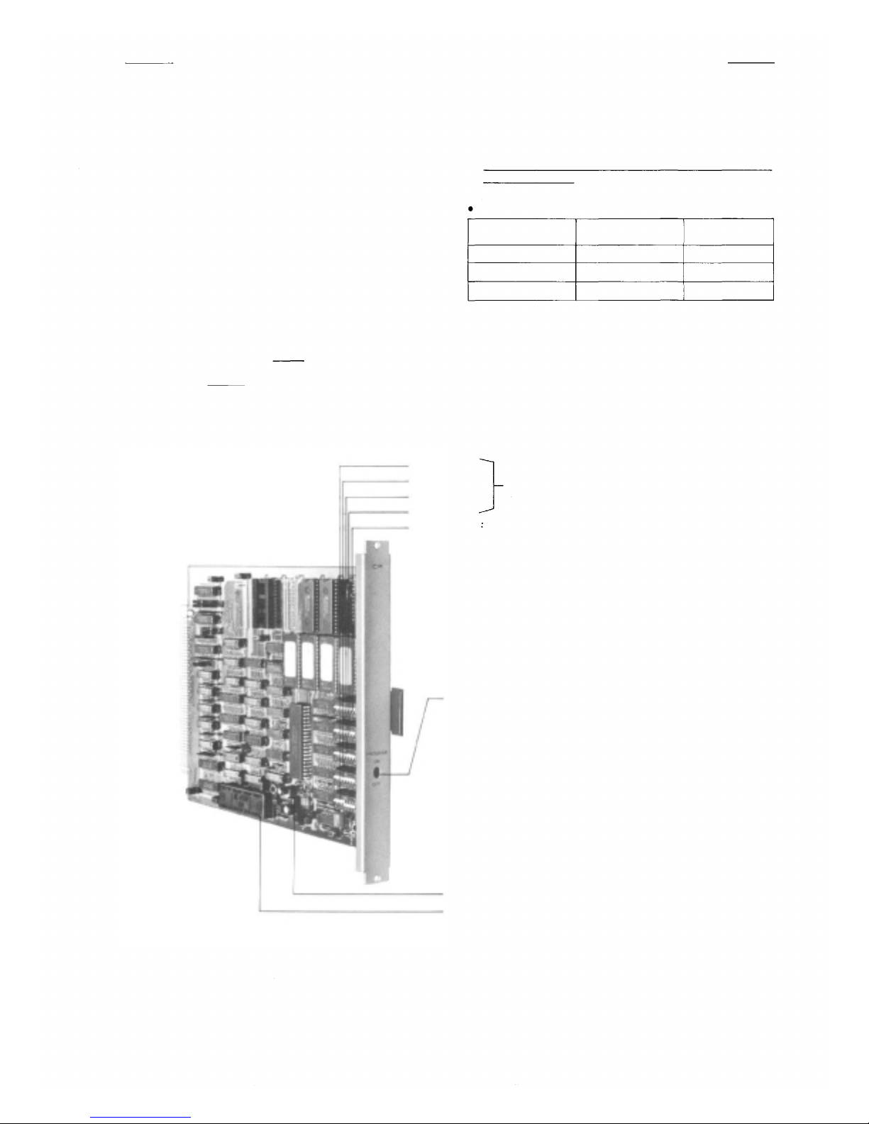
8. SETTING OF CHANNEL SELECT SWITCH OF TRANSMITTING UNIT (DT-E11)
AND WORD SELECT SWITCH OF RECEIVING UNIT (DR-B61)
NOTE
1. Connect the DT-E11 and DR-B61 to Exchange correctly. (Refer
to operation manuals of DT-E11 and DR-B61).
2. Set the function select switches (DIP SWITCH) on CP-64 correctly
and be
sure
to
enter
initial
registration at programming station No.200.
3. Remove the front panel of Data Transmitting Unit (DT-E11) and
take out the printed circuit board. Then set the channel select
switches located on the printed circuit board, according to the
Connecting
Cable YR-802
or YR-806
One Pair Cable
Connecting
Cable YR-803
programming
To other DR-B61
and
function
necessary functions such as IN/OUT Annunciation, Calling Party
Indication etc, and replace in the Unit.
(Refer to 12. Explanation of Data Transmitting Unit Output
Data, Page 48).
4. The DT-E11 sends out 512 bit data (16 bit x 32 words) to
control relays on Data Receiving Unit (DR-B61). Therefore set
the two word select switches on DR-B61, according to necessary
output mode. SW-1 is fo r Relay No.1 to No.16 and SW-2 is for
Relay
No.17
to
No.32.
See
Page
51 for
(Refer to Explanation of Date Receiving Unit Output Channels.)
5. Connecting Cable YR-802 is used for the Rack mounting system.
Connecting Cable YR-806 is used for the Standard Cabinet
mounting system with only One (1) DT-E11 unit.
details.
To other
DT-E11
CHANNEL SELECT
Switch (SW-1)
To other RD-B61
— 43 —
WORD SELECT Switch
(SW-1, SW-2)
Page 45

9. DIP SWITCH TABLE FOR DATA TRANSMITTING AND RECEIVING UNITS
Exchange
Data Transmitter
CH.1)
for
above
(s) (as
DR-B61
to
Data Receiver
Relay Output No.
CHANNEL SELECT Switch.
connected
may be
DT-E11
of
output
Each channel
Note:
shows the Head of a Slide Switch
— 44 —
WORD SELECT Switch
Page 46

10. SYSTEM DIAGRAM OF DATA TRANSMITTING AND RECEIVING UNITS
(Single Exchange)
YR-802
or
YR-806
YR-803
YR-803
YR-803
YR-803
YR-803
Exchange
Data Transmitting Unit
Make-Break Output
(512/100 contacts)
One-shot Make Output
(500/50 contacts)
(1 ) 4 Decimal Digits Output (9 Units)
(2) Decimal Output (9 Units)
(3) 8 Selectable Make Output (9 Units)
(4) Pager Control (100 contacts)
(5) 8 selectable One-shot Make Output
Decimal Output (9 9 Units)
8 Selectable Make Output
(64 Units)
(9 Units)
YR-810
Terminal Board
Two wires
Stations
<Data Receiver
(Equipment using DR-861 )>
a. Conference Room.
b. Reception Room.
Room Condition Indication.
Destination Indication, etc.
Room Condition Indication.
Destination Indication.
VTR.
c. Out
d. Waiting Roo m
YR-803
YR-803
YR-803
YR-803
YR-803
YR-803
YR-803
YR-803
YR-803
Calling Party Indication.
Numerical Type ( 1)
Calling P arty Indication.
Numerical Type (2)
Calling Party Indication
Lamp Type (1 )
I
Calling Party Indication.
Lamp Type (2)
Calling Party Indication.
Lamp Type (3)
Calling Party Indication.
C
Lamp Type ( 4)
Destination Indication (1)
Destination Indication (2}
In/Out Annu nciations (1)
(504 contacts)
Calling Party Display
Board
Indication by decimal
digits.
Calling Party Displ ay
Board.
1 Station 1-lamp
Indication.
8 stations
(8 groups)
Destination
Indication
Station No.
No. 201~232
In/Out Annunciation
Display Board
In/Out Annunciations(2)
(496 contacts)
— 45 —
Page 47

Enlarged Block Diagram of Calling Party Indication
Exchange
YR-802
or
YR-806
YR-803
Data Transmitting Unit
Two wires
<Calling
Party
Display
Panel
with
DR-B61>
Station numbers of
Called Parties with Indicator
16 units
16 units
YR-803
YR-803
YR-803
YR-803
2 units
2 units
2 units
2 units
— 46 —
Page 48

11. SYSTEM DIAGRAM OF DATA TRANSMITTING AN D RECEIVING UNITS
(Tie-line System)
Note: TI-62 : Tie-line Interface Unit
— 47 —
Page 49

12. EXPLANATION OF DATA TRANSMITTING UNIT OUTPUT CHANNELS
Make/Break Output
(512/100 contacts)
One-shot Make Output
(500/50 contacts)
(1) 4 Decimal digits output
(9 units)
(2) Decimal Output
(9 units)
(3) 8 Selectable Make Output.
(9 units)
(4) Pager Control Output
(100 pagers)
(5) 8 Selectable One-shot
Make Output (9 unit)
Decimal Output
(99 units)
8 selectable make Output
(64 units)
Make/Break contacts can be available
at any Master st ation.
One-shot make contacts can be
available at any Master station.
Indicate by 7 segments LEDs.
10 Selectable Decimal Outputs are
available with 7 segments LEDs.
One contact out of 8 selectable make
o
utputs is obtained. "Clear" ope-
ration makes all 8 relays break.
Make output (100 contacts) is
available for pager control.
One contact out of 8 selectable make
outputs is obtained for about 1
or 2 seconds.
10 Selectable Decimal Outputs are
available with 7 segments LEDs.
One contact out of 8 selectable make
outputs is obtained. "Clear" ope-
ration makes all 8 relays break.
• Door Remote
• IN/OUT Annunciation
•
ITV
camera select
• VTR control
•
Prescription annunciation
• Room condition indication
• Destination indication
• Pager
• VTR control
• Room condition indication
•
Destination indication
• Room condition indication
•
Destination indication
Calling Party Indication
Numerical-type (1)
Calling Party Indication
Numerical-type (2)
Calling Party Indication
(One Station; One Lamp) (1)
Calling Party Indication
(One Station; One Lamp) (2)
Calling Party Indication
(One Station; One Lamp) (3)
Calling Party Indication
(One Station; One Lamp) (4)
Destination
Indication (1)
Destination
Indication (2)
In/Out Annunciation (1)
In/Out Annunciation (2)
When a station with a Display Board
is called, calling party number is
indicated until the conversation is
over and also when the called station
is busy or in privary.
Max. 256 Calling station numbers can
be indicated when designated called
station with Display Board is called.
The numbers of call ed stations having
an indication panel can be program-
med at No.200 station.
When a person makes his own
Personal Number Programming at the
station, th e stat ion number at which
the registration was made can be
indicated by th e lamp.
Personal in and out registration can
be accomplished at any Master
station by using personal numbers
Max. 1000 IN/OUT annunciations
may be done.
• The number of calle d s tat ions
are No.201~No.216.
• The number of called stations
are No.217~No.232.
• The group number of called
station(s). No. 1~2
• The group number of called
sta tio n(s). No.3~4
• The group number of cal led
station(s). No.5~6
• The group number of called
station(s). No.5~6
• Personal number No . 1000~1015
• Personal number No.1016~1031
• Personal number No.1000~1503
• Personal number No.1504~1999
(504 persons)
(496 persons)
— 48 —
Page 50

13. EXPLANATION OF DATA RECEIVING UNIT OUTPUT DATA
13-1 Channel 1 (CH. 1) Make/Break Output
Exchange
Data Transmitter
CHANNEL SELECT Switch
(Dial Operation)
(Relay Make)
(Relay Break)
XXX: 000 ~ 511 (512 contacts)
XX: 00 ~ 99 (100 contacts)
Relay Output No.
Each Relay Output shows
Relay Contact Number.
Note:
shows the Head of a Slide Switch
— 49 —
WORD SELECT Switch
Page 51

13-2 Channel 2 (CH. 2) One-Shot Make Output
Each Relay Output shows
Relay Contact Number.
— 50 —
— 50 —
Page 52

13-3 Channel 3 (CH. 3
CHANNEL SELECT Switch
(Example)
(1) 4 Decimal Digits Output
(2) Decimal Output
(3) 8-Selectable Make Output
)
(1) 4 Decimal Digits Output (9 units) (2) Decimal Output (9 units)
(3) 8-Selectable Make Output (9 units) (4) Pager Control Output (100 contacts)
(5) 8-Selectable One-shot Make Output
(9 units)
Display
8-Select.
Decimal
X
1~9
1~8,0 (Clear)
1~9
Bindary Negative
Logic Output
Unit No.4 Condition"1"
Unit No.6 Condition "8"
1: Relay Make
0: Relay Break
Y
0~9
Unit No.4 Condition "1"
Unit No.6 Condition "8"
Each Relay Output shows
Relay Contact Number.
— 51 —
Page 53

13-4 Channel 4 (CH. 4) Decimal Output (99 Units)
Exchange
Data Transmitter
CHANNEL SELECT Switch
(Example)
Unit No.24 Condition "3"
Binary Negative Logic "3"
Unit No.48 Condition"0"
Binary Negative Logic "0"
1: Relay Make
0: Relay Break
WORD SELECT Switch
— 52 —
Page 54

13-5 Channel 5 (CH. 5) 8-Selectable Make Output (64 Units)
CHANNEL SELECT Switch
(Example)
Unit No.8 Condition "1"
Unit No.10 Condition "8"
1: Relay Make
0: Relay Break
— 53 —
Page 55

13-6 Channel 6 (CH. 6) Calling Party Indication Numerical Type (1)
7 Segments Display of "Calling Station No.", "Waiting Station No." and "Total Number of Waiting
Stations". Total Number of Station with Indications, 16 stations/Channel (32 stations/2 Channel)
No.201
No .202
No
.203
(Example)
Station No.205
Lamp "OFF" Condition
No.204
No
.205
No.206
No.207
No .208
No .209
No.210
No.211
d.c.: Digit of Calling Station No.
d.w.: Digit of Wa iting Station No
t.n.w.: Total Number of Waiting
Stations.
—lo gic : Binary negative logic
1: Relay Make
0: Relay Break
— 54 —
No .212
No.213
No.214
No
WOR D SELECT Switch
No.215
.216
Page 56

13-7 Channel 7 (CH. 7) Calling Party Indication Numerical Type (2)
7 Segments Display of "Calling Station No.", "Waiting Station No." and "Total Number of Waiting
Stations". Total Number of Station with Indications, 16 stations/Channel (32 stations/2 Channel)
No
.217
No.218
No.219
No.220
No
.221
No.222
d.c.: Digit of Calling Station No.
d.w.: Digit of Wa iting Station No
t.n.w.: Total Number of Waiting
Stations.
—logic: Binary negative logic
1: Relay Make
0: Relay Break
No
.223
No.224
No.
225
No
.226
No.227
No.228
No.229
No.230
No
.231
No
.232
— 55 —
Page 57

13-8 Channel 8 (CH. 8) Calling Party Indication (Lamp Type) (1)
Each "Calling Station" or "Waiting Station" is shown by Each Lamp of Indic ati on.
Total Number of Station with Indications: 2 Stations/Channel (8 Stations /4Channels)
Total Number of Calling Stations: Max. 256 Stations/Each Indication
Data Receiver
Relay Output No.
Station No.
with Indication
Each Relay Output shows
"Calling Station No."
— 56 —
Page 58

13-9 Channel 9 (CH. 9) Calling Party Indication (Lamp Type) (2)
Each "Calling Station" or "Waiting Station" is shown by Each Lamp o f Indication.
Total Number of Sta tion wit h Indications: 2 Stations/Channel (8 Stations/ 4 Channels)
Total Number of Calling Stations: Max. 256 Stations/Each Indication
Relay Output No. with Indication
Station No.
Each Relay Output shows
"Calling Station No."
WORD SELECT Switch
— 57 —
Page 59

13-10 Channel 10 (CH. 10) Calling Party Indication Lamp Type (3)
Each "Calling Station" or "Waiting Station" is shown by Each Lamp of Indication.
Total Number of Station with Indications: 2 Stations/Channel (8 Stations/4 Channels)
Total Number of Calling Stations: Max. 256 Stations/Each Indication
Data Receiver Relay Output No. with Indication
Station No.
Each Relay Output shows
"Calling Station No."
— 58 —
Page 60

13-11 Channel 11 (CH. 11) Calling Party Indication Lamp Type (4)
Each "Calling Station" or "Waiting Station" is shown by Each Lamp of Indication.
Total Number of Station with Indications: 2 Stations/Channel (8 Stations/4 Channels)
Total Number of Calling Stations: 256 Stations/Each Indication
Each Relay Output s hows
"Calling Station No."
— 59 —
Page 61

13-12 Channel 12 (CH. 12) Destination Indication (1)
(Dial Operation)
• Registration of Personal Number
• Cancellation of Personal Number
Personal Number: Max. 32 persons (No.1000~1031)
Station Number wh ich s hows Person's Destination: Max. 32 stations (No.201~232)
Personal
Number
No.1000
No.1001
No.1002
No.1003
No.1004
No. 1005
EXAMPLE
Indication Panel-lamp on
A person "No.1006" registers his
Personal Number at the station
"No.216", then the Relay contact
"No.216" turns into "Make".
Each Rela y Output shows
"Station No. of Person's Destination"
Each Relay Output shows
"Station No. of
Person's Destination"
No.1006
No.1007
No.1008
No.1009
No.1010
No.1011
No.1012
No.1013
No.1014
No.1015
— 60 —
Page 62

13-13 Channel 13 (CH. 13) Destination Indication (2)
(Dial Operation}
• Registration of Personal Number
• Cancellation of Personal Number
Personal Number: M ax. 32 persons (No.1000~1031)
Station Number w hich shows Person's Destination: Max. 32 stations (No.201~232)
CHANNEL SELECT Switch
EXAMPLE
Indication Panel-lamp on
A person "No.1022" regis ters his
Personal Number at the s tation
"No.216", then the Relay contact
"No.216" turns into "Make".
Each Relay Output shows
"Station No. of Person's Destina-
tion"
Each Relay Output shows
"Station No. of
Person's Destination"
WORD SELECT Switch
— 61 —
Page 63

13-14 Channel 14 (CH. 14) In/Out Annunciation (1 ) (504 persons)
(Dial Operation)
Personal Number Registration
Personal Number Cancellation
(Relay Make) X X X : 000 ~ 503 (504 contacts)
(Relay Break)
Relay Output No.
Each Relay Output shows
last 3 digits (xxx) of Personal
Number
— 62 —
Page 64

13-15 Channel 15 (CH. 15) In/Out Annunciation (2) (496 persons)
(Dial Operation)
Personal Number Registration
Personal Number Cancellation
(Relay Make) X XX : 000 ~ 499 (500 Contacts)
(Relay Break)
Relay Output No.
Each Relay Output shows
last 3 digits (xxx) of Personal
Number
— 63 —
WORD SELECT Switch
Page 65

TOA ELECTRIC CO, LTD.
KOBE, JAPAN
 Loading...