

Page 1
For
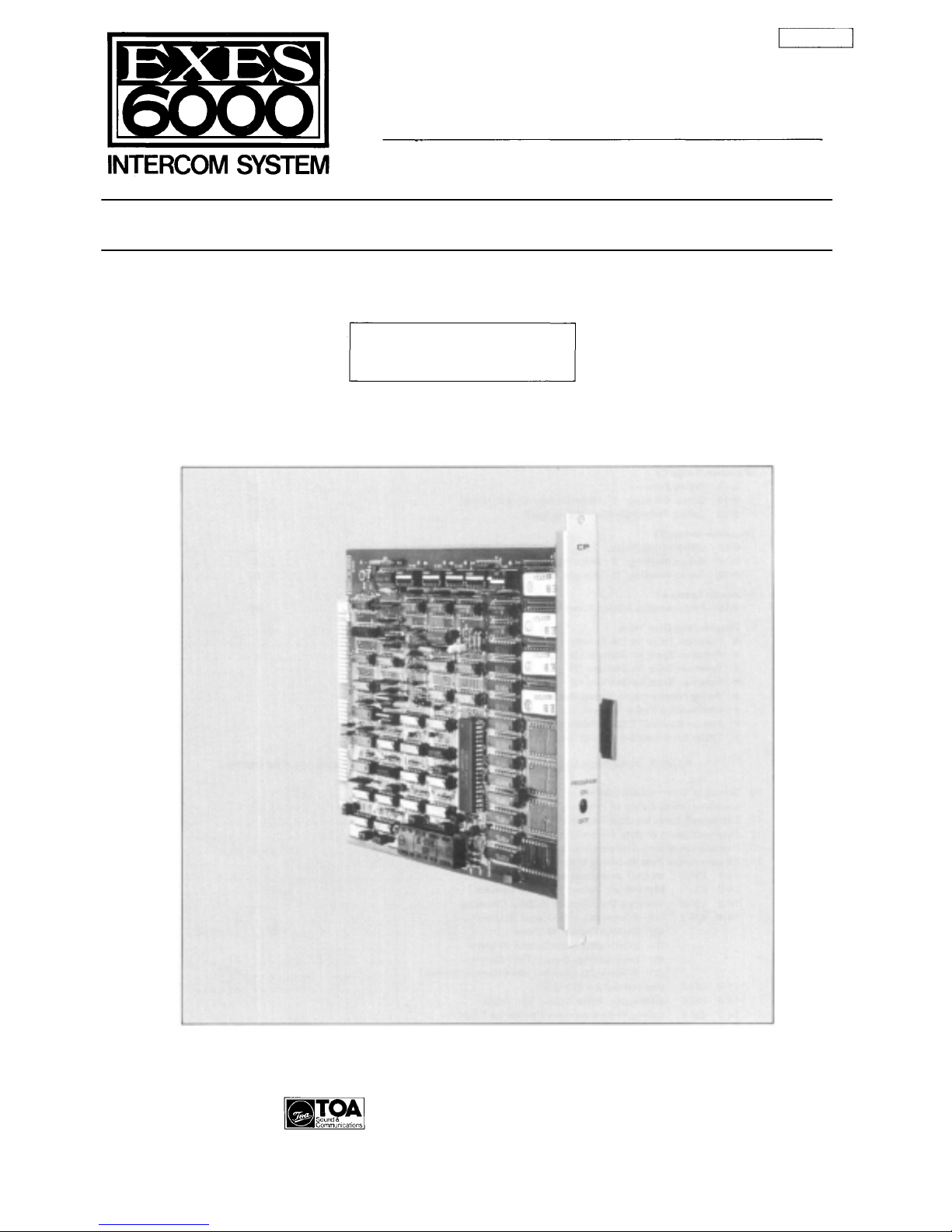
EXES-6000
CP-62
TOA EXES-6
Central Processing Unit for Single Exchange
000
INTERCOM SYSTEM
CP-62
INSTALLATION HAND BOOK
TOA ELECTRIC CO., LTD.
KOBE, JAPAN
133-21-079-2
Page 2

CONTENTS
INTRODUCTION TO THE INSTALLATION
FUNCTIONS WHICH REQUIRE ADDITIONAL UNITS
- PART 1. OPERATING OF CP UNIT AND NO.200 PROGRAMMING -
MANUAL
FOR EXES-6000
Page
2
3
1. Precautions for Installation of CP-62
2.
Initial
CP-62
3. Troubleshooting
4. CP-62 DIP Switches for Function Selection
5. Setting DIP Switch Positions for Four (4) different types of Dial Operation
6. Dip Switch Selection and Station No.200 Programming for Each Function
7. Function Code Table for Station No.200 P rogr amming
8. Stati on No.200 Programming for Each Function
[Function Group A ]
8-1 Executive Priority
8-2 Continuous Calling Tone
8-3 Stations Allowed Access to All Call
8-4 Stations Allowed Access to Conference
8-5 Automatic Access to Paging
8-6 Stations Allowed Access to One-shot Make Output
8-7 Stations Allowed Access to Make/Break Output
8-8 Stations Allowed Access to 8 Selectable (One-shot Make) or Decimal Output
8-9 Stations Allowed Access to 4 Decimal Digits Output
[Function Group B]
8-10 Secretary Transfer
8-11 Master/Sub Relationship
8-12 Group Hunting
[Function Group C]
8-13 Paging Zo ne
8-14 Group Blocking 1 : Establishment of each Group
8-15 Calling Party Indication (Lamp Type)
[Function Group D]
8-16 Combination Paging
8-17 Group Blocking 2 : Allowing Calls among Groups
8-18 Group Blocking 3 : Allowing Group Access to Paging
[Function Group E]
8-19 Programmable Station Numbering
9. Programming Data Table
set up
Function Table for the System
Function Table for Stations (1)
Function Table for Stations (2)
Function Table for Stations (3)
Paging Priority and/or Paging Response Table
Combination Paging Table
Station Numbers Table for Calling Party Indication (Lamp Type)
Tables for Group Blocking (3 Tables)
- PART 2. FUNCTION SELECTION FOR DATA TRANSMITTING AND RECEIVING UNITS -
FUNCTION CODE
50
51
52
53
54
56
57
58
59
60
61
62
70
71
72
80
81
82
90
5
6
7
8
11
12
15
18
18
19
20
21
22
24
25
26
27
28
29
30
31
32
33
34
35
36
37
39
39
40
41
42
43
43
43
44
10. Setting of Channel Select Switch of Transmitting Unit (DT-E11)
and Word Select Switch of Receiving Unit (DR-B61)
11. DIP Switch Table for Data Transmitting and Receiving Units
12. System Diagram of Data Transmitting and Receiving Units
13. Explanation of Data Transmitting Unit Output Channels
14. Explanation of Data Receiving Unit Output Channels
14-1 CH-0 IN-OUT Annunciation (500 Contacts)
14-2 CH-1 Make/Break Output (512/100 Contacts)
14-3 CH-2 One-shot Make Output (500/50 Conta cts)
14-4 CH-3 (1) 4 Decimal Digits Output (9 Units)
(2) Decimal Output (9 Units)
(3) 8-Selectable Make Output (9 Units)
(4) Pager Control Output (100 Contacts)
(5) 8-Selectable One-shot Make Output (9 Units)
14-5 CH-4 Decimal Output (99 Units)
14-6 CH-5 Selectable Make Output (64 Units)
14-7 CH-6 Ca lling Party Indication (Numerical Type) (1)
14-8 CH-7 Calling Party Indication (Numerical Type) (2)
14-9 CH- 8 Calling Party Indication (Lamp Type) (1)
14-10 CH- 9 Calling Party Indication (Lamp Type) (2)
14-11 CH-10 Destination Indication (1)
14-12 CH-11 Destination Indication (2)
46
47
48
50
51
51
52
53
54
54
54
54
54
55
56
57
58
59
60
61
62
— 1 —
Page 3
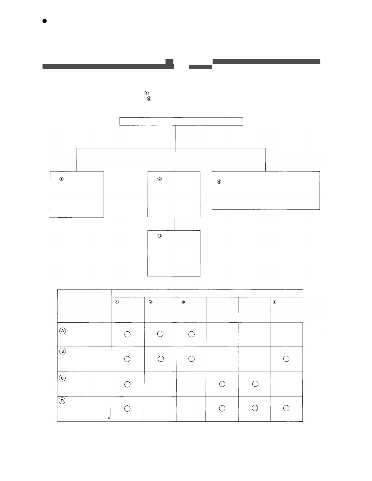
INTRODUCTION TO THE INSTALLATION MANUAL FOR EXES-6000
This manual forms part of the Installation Manual for TOA INTER-
COM SYSTEM EXES-6000.
You may add the CP-62 to your TOA INTERCOM SYSTEM EXES-
-6000, according to your specific needs, to obtain various other
functions. Correct operation of these additional functions is
performed by simply conecting the additional equipments/devices.
Provision of such additional function requires the following:
(1) Connection of the additional equipment, as required.
(2) Selection of func tion s which satis fy your needs and setting up
these functions in the respective equipment.
For (1) Connections of Equipment, etc., refer to " Installation
Handbook of Model EX-610/620 EXCHANGE" or " Operation
Manual of Data Transmitting and Receiving Units", etc.
INSTALLATION HAND BOOK OF EXES-6000
EXES-6000
EX-610/620
INSTALLATION
HAND BOOK
OF EXCHANGE
133-21-100-9
EXES-6000
CP-62
INSTALLATION
HAND BOOK
133-21-079-2
(This Hand Book)
not
This "Installation Handbook of CP-62"deals principally with (2 )
Selection of functions and setting up of respective equipment.
There are certain minimum installation requirements to be met even
though you may not need many additional functions or additional
equipment,
(Page 6 )".
it is
still
necessary
to
read
"2. Initial CP-62
Set Up
When you may use only some of the additional func-
tions or equipments, it is not necessary to read instructions on
unrequired functions. Make sure, however, that careful study of the
necessary parts of this booklet should be done before proceeding
further.
Note: R efer to "Insta llation handbook of CP-63" when i nsta lling
Tie-line system.
DATA TRANSMITTING AND RECEIVI NG UNIT
"DT-E11 OPERATION MANUAL" 133-05-094-1A
"DR-B61 OPERATION MANUAL" 133-05-095-0
EXES-6000
CP-62
INITIAL
CHECKING
SHEET FOR
THE SYSTEM
133-21-083-9
Manuals Necessary for Installation of Exchange.
SYSTEMS OF
EXES-6000
Normal Conversation
and Paging System
Normal Conversation
and Paging System
with Display and
Control Functions
Tie-line System with
Normal Conversation
and Paging Functions
Tie-line System with
Normal Conversation,
Paging, Display
and Control Function
EX-610/620
INSTALLATION
HAND BOOK
OF EXCHANGE
CP-62
INSTALLATION
HAND BOOK
REQUIRED INSTALLATION HAND BOOK
CP-62
INITIAL
CHECKING
SHEET
CP-63
INSTALLATION
HAND BOOK
CP-63
INITIAL
CHECKING
SHEET
DATA TRANSMITTING
AND RECEIVING UNIT
OPERATION MANUAL
— 2 —
Page 4
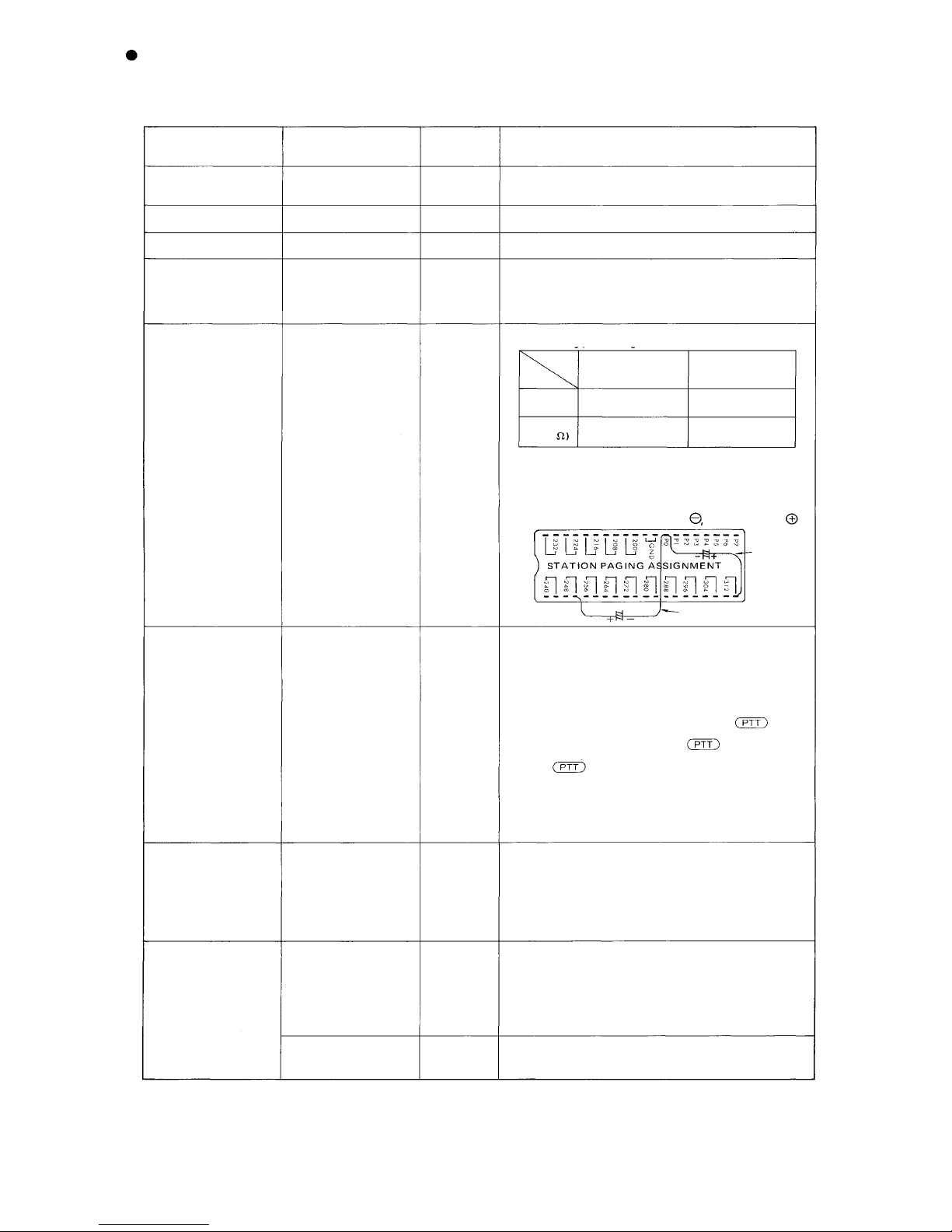
FUNCTIONS WHICH REQUIRE ADDITIONAL UNITS
Those functions of the CP-62 which require either the addition of specific units or processing in existing units are as mentioned below.
Before installation and adjustment of equipment, make sure to check your system.
(For
Data
Transmitting
and
Receiving
units,
refer
to
Part
2.
"Function
Selection
for
Data
Transmitting
and
Receiving
units"
Page
46.)
Function
Talk-Back from
paging speaker
Conference
External PA Paging
Station Paging
(including Paging
Priority)
All call plus 15
individual paging
zones
Additional Equipment
Required
Talk-Back Unit
Conference Unit
Paging Interface Unit
Paging Interface Unit
Paging Interface Unit
Unit Model
Number
TK-12
CL-62
PI-62
PI-62
PI-62
(2
pcs)
Remarks
Not yet available for sale.
External PA Equipment is required.
1. Wiring of "Station Paging Assignment" located at
the back of the frame of the Exchange.
2. Cutting of LM-62 jumper wire to split station paging
system.
1. PI-62 Type 1 is different from PI-62 Type 2 in the
following
parts
being
used
in
each
unit.
PI-6 2 Typ e 1
Type
All- call +7 Paging
(255)
Zones (No. 0-7)
Connected
Not mounted
to
GND.
Parts
Jumper
Wire (JW)
R100
(220K
2. Solder the electrolytic capacitor (33 µ F ) to the
terminals, and "PO" and "No. 319" (paired with No.
312) for EX-620, "PO" and "No. 255" (paired with
No. 248) for EX-610 o f "Station Paging Assignment"
on the rear of exchange frame. Do not connect No.
319
Polarity of capacitor . . . PO : No. 319 (255):
PI-62 Type 2
8 Zones (No. 8-15)
without All-call
Disconnected
Mounted
For EX-620
Press-to-talk
Control
Emergency All-call
Paging
Indication and
Control
Paging Interface Unit
Paging Interface Unit
Data Transmitting Unit
Data Receiving Unit
PI-62
PI-62
DT-E11
DR-B61
For EX-610
1. Insert the PI-62 into the place allocated to the PI-62
Type 2.
2. You can use whichever type, type 1 or 2, of the
PI-62 but be sure not to connect the terminal
"No.319" (paired with the terminal No.312) of the
"Station Paging Assignment" to the ground (GND).
3. When you call any of the stations from No.232
(132) through 239 (139) and press the key,
the corresponding relay contact in the PI unit will
close and open in step with the key.
For example, calling the station No.232 (132) using
the key causes the PI's relay zero (0) to
operate in step or calling the station No.234 causes
the PI's relay 2 to operate in step.
This feature may be used for Door Remote or tor
controlling Radio Transmitting/Receiving Equip-
ment through user provided interface.
This func tion w or ks when the Handset substation
connected to No. 247 (147) is picked up or when the
privacy switch of a Hands-free Substation connected to
No. 247 (147) is moved fr om t he ON to OF F position. If
your wish to use this specified line for any other
purpose, you need to make the device incorporating the
circuit similar to the one of the station but modified to
suit such purpose.
The number tha t can be mounted on the cabinet-mount
type exchange is one (1). Use the connection cable
YR-806.
When more than 2 pieces are mounted, we suggest you
use rack-mount type exchange. For connection between
the exchange and the DT-E11, use the YR-802, and
THE YR-803 for extension of the DT-E11.
Such devices as indicator, control unit, etc. can be made
by using this unit and 24 VDC power supp ly.
— 3 —
Page 5
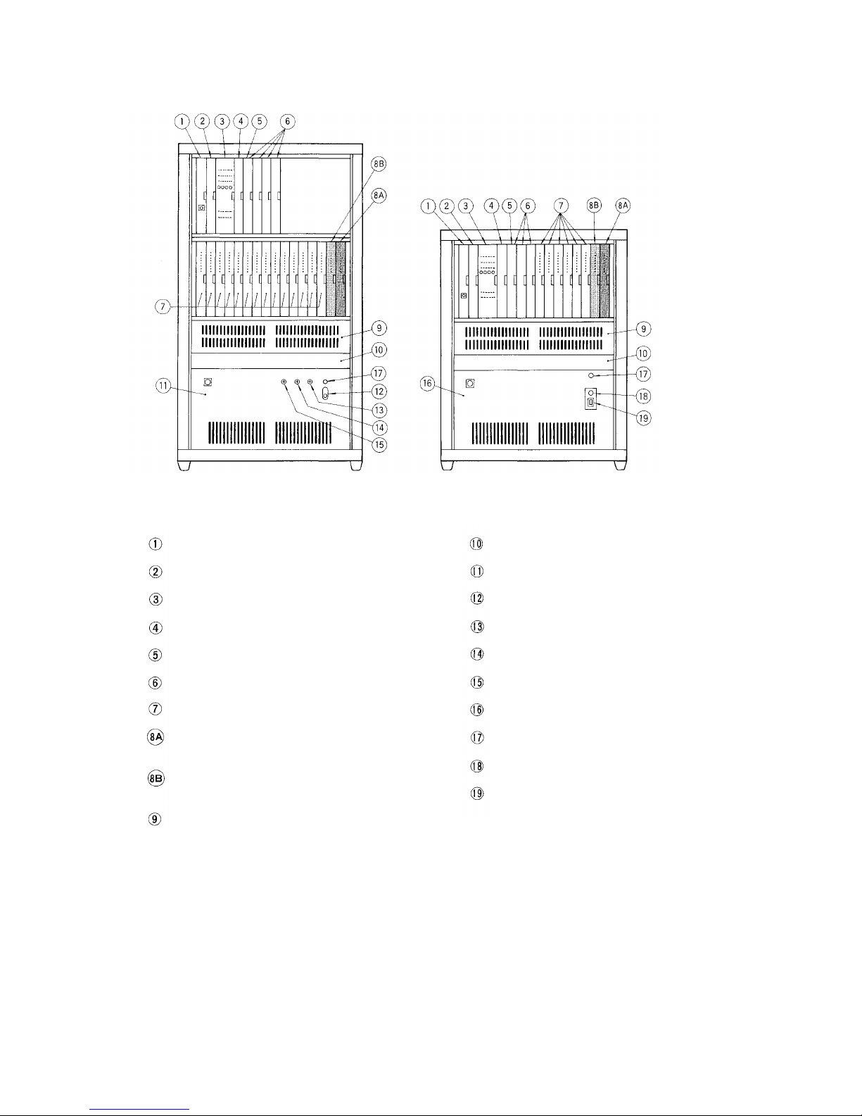
Mounting Example of Cabinet-mount Type Exchange
(All-Call Paging and 15 Indivisual Zone Paging)
Exchange EX-620
Central Processing Unit CP-62
Output Control Unit OC-62
Highway Control Unit HC-62
Signal Generating and Distributing Unit SG-62
Conference Link Unit CL-62
Duplex Link Unit DL-62
Line Modem Unit LM-62
Paging Interface Unit PI-62 (Type 1)
(Zone 0- 7 with All-Call Paging)
Paging Interface Unit PI-62 (Type 2)
(Zone 8-1 5 without All-Call Paging)
Perforated Panel PF-022G
Exchange EX-610
Data Transmitting Unit DT-E11
Power Supply Unit DS-620
Power Switch
AC Fuse
DC Fuse
Battery Fuse
Power Supply Unit DS-610
Power Indication Lamp
Battery Power Indication Lamp
Buzzer Stop Switch
— 4 —
Page 6
PART 1. OPERATING OF CP UNIT AND NO. 200 PROGRAMMING
1. PRECAUTIONS FOR INSTALLATION OF CP-62
Please read following instructions c arefull y to ensure proper operation of the CP-62.
1. Be careful about damage by static electricity as the CP-62
incorporates CMOS IC's. Do not touch components and connectors.
2. Turn off the AC power switch when you take out or insert the
CP-62 unit, or any other unit.
3. Al way s insert the CP-62 unit into the "CP" slot. Otherwise,
there is a danger that the unit will be damaged.
4. Make sure mini-jumper for battery back-up is always placed in
ON position each time it is used.
5. Incorrect setting of function select switches may lead to incor-
rect performance.
6. Even if you do not need programming functions, be sure to carry
out initial programming and registration at station No.200 wh en
you install the new unit. Otherwise, some other functions may
not work properly.
7. The Ni-Cd battery GB50-3FA1 is capable of saving important
memory registration data even at times of power failure.
To keep the battery fully charged, do not cut the power off f or
long hours during the first 8 days after new installation. The
CP-62 unit is capable of maintaining the programmed data for
the period of 4 weeks after fully charged even in the event of
long hours of power failure.
(About 4 weeks (25°C), About 8 days (40°C))
FUNCTION SELECT SWITCHES
8. We suggest you replace the soldere d button battery GB50-3FA1
Expected Life Span of small Ni-Cd Battery
•
Ambient temperature
of exchange
9. When shipping the CP-62 unit independently, place the mini-
(115-42-031 -9) with the new one according to the following list
that shows an expected life span of the battery.
Be sure to make the sta tio n No.200 programming after replace-
ment of the battery.
Ambient temperature
of battery
0°C
25° C
40° C
jumper for battery back-up in "OFF" position. Cover the CP
back with cardboard, wrap connector section in aluminium foil
and put it in a conductive bag.
10° C
35° C
55° C
Life span
About 5 years
About 4 years
About 2 years
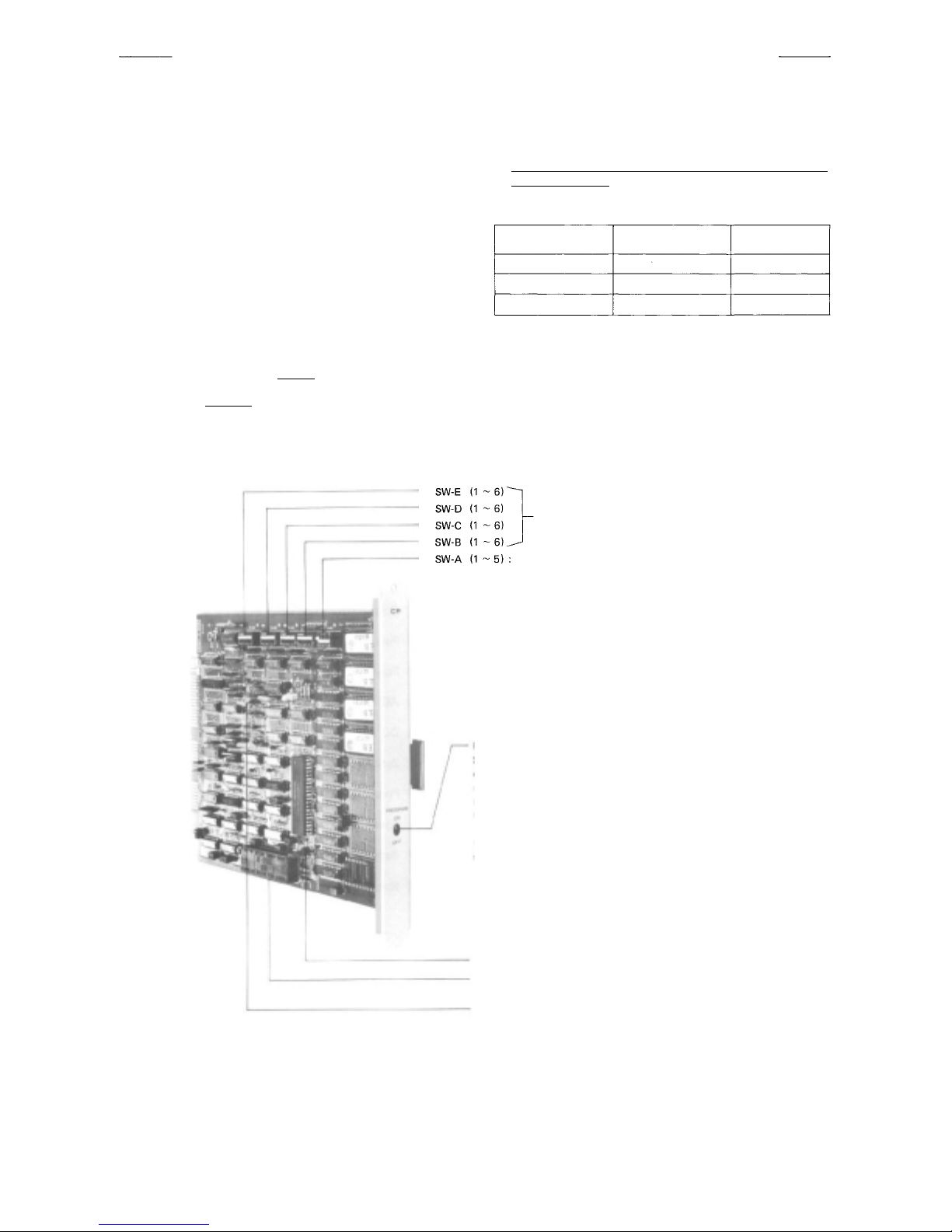
e switches select functions.
Thes
K SELECTION, PAGING AMP. REMOTE
LIN
PROGRAM SWITCH for #200 Programming
Set this to"ON"position only at time of initial programming of the
exchange and registration of functions. In this case, station No.200
is "programming sation" but becomes a normal station when switch
is placed in "OFF" position.
Note:
Depending on the selection of the Numbering Schedules, station
No.100 or 20 or 10 is made the programming station instead of the
station No.200.
MINI-JUMPER for battery back-up (JP1)
Ni-Cd BATTERY GB50-3FA1 (3.6V 50mAh)
FIXED MINI-JUMPER (JP2)
Note: Do not removal
— 5 —
Page 7
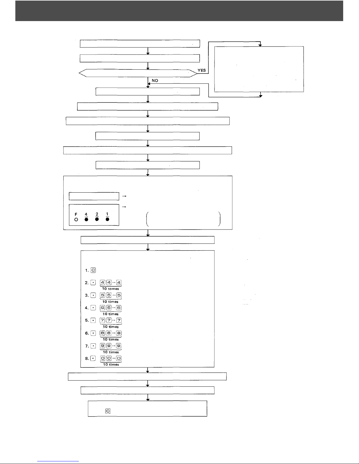
2. INITIAL CP-62 SET UP
Make sure that you have turned off the AC power switch.
Connect the exchange, terminal boards and stations.
Are Data Transmitting and Receiving Units connected?
Remove CP-62 from the exchange.
Set mini-Jumper (JP1) for battery from OFF to ON position.
Set function selection switches (SW-A ~ SW-E) for required functions.
Insert the CP-62 into the exchange.
Put all 4 "Link select" switches of the HC unit upward.(Link No. 15)
Look
COD
at indication of LINE ADDRESS of HC (14 LEDs) and SIGNAL
AL
E indication (4 LEDs)
L LED lamps are out
SIGNAL CODE indication
Switch on the exchange.
Memory is normal
Some errors in memory
Lighted lamps of LINE A DDRESS
LEDs indicate er roneous MEMORY
ICs. See Section 3 (Page 7)
1. Connect Data Transmitting Unit (DT
E11) and Data Receiving Unit (DR
B61).
2. Set channel select switches (CHAN-
NEL SELECT) of DT-E11.
3. Set word select switches (WORD
SELECT) of DR-B61.
-
-
Place program switch on front panel of the CP in "ON" position.
Dial operation from station No. 200.
— Initial programming of the exchange —
Dial the Following:
Dial ton e will be heard
(Station No. 200 (100) becomes a programming station)
Confirmation tone will be heard. *2
(Clears function group S)
Confirmation tone will be heard. *2
(Clears function group A)
Confirmation tone will be heard. *2
(Clears function group B)
Confirmation tone will be heard *2
(Clears function group C)
Confirmation tone will be heard. *2
(Clears function group D)
Confirmation tone will be heard. *2
(Clears function group E)
Confirmation tone will be heard. *2
(Clears personal numbers, single digit dial
numbers and remote numbers)
Program necessary functions (Refer to separate instructions for each function) *2
Place program s witch on front panel of the CP in "OFF" position.
Dial operation from station No. 200. *1
(Station No. 200 becomes a normal station.)
*1
Note:
*1; Depending on the selection of
the Numbering Schedules,
station No. 100, 20 and 10
can function as the Program-
ming Station instead of Station
No.
200.
*2; If there is any error in CMOS
memory, y ou hear calling
tone instead of confirmation
tone.
— 6 —
Page 8
3. TROUBLE SHOOTING
3-1 Check of ROM & NMOS-RAM - No calls on the system.
1. Put the 4 "LINK SELECT" switches of the HC upward (Link No. 15
SELECT) and switch on the AC power of the exchange.
2. If there is no error, the indication lamps will not light.
3. In the event of a memory error, the lamps may light as shown in the example
of
Fig.
4. The error indications will remain on until you use Link No. 15 f or com-
1.
munications.
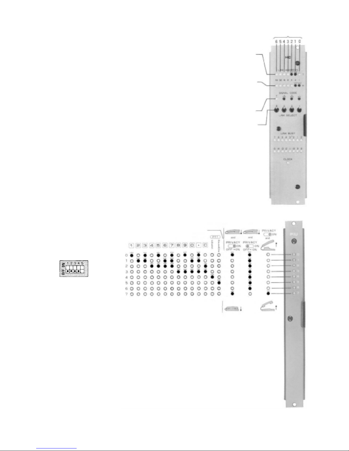
3-2 Confirming of the CP normal working
If the CP, OC and HC are working normally, the HC's indication lamps of LINE
BUSY, LINE ADDRESS and SIGNAL CODE go out.
When any of the lamps lies alight, it is possible that any of the CP, OC or HC is
faulty.
Check first that the CLOCK lamp of the HC is lighting, then confirm that the
CP is working normally by hearing the clicking sound of the PI unit's relay which
is produced when the relay is activated through dial operation of the paging.
If the CP is found working normally, chances are that the HC is faulty, followed
by the OC.
3-3 Check of CMOS-RAM (Programmed data memory)
You hear calling tone instead of confirmation tone, if there is CMOS memory
error at the time of initial programming and registration using station No. 200,
or at the time of registration to Single Digit Number or Personal Number or
Remote Number.
3-4 Dial receiving test
1.
Instead
of the
PI-62
unit,
use the
PIU-52A
(a
unit
used
in the
System) to check the dial receiving section of the CP also to check if the
signal is correctly transmitted as dialed from the station to be tested.
2. If you
place
all
"LINK
"OFF" position, conversation is impossible but the dial code from each
SELECT"
switches
(1 ~ 4) of
SW-A
station is indicated on the LED's of the PIU as dialed. Use this to find the
cause of a ny fault of receiving dial information.
3. With use of the PI-62 unit fitted
with no LED, you can also
check that the CP receives the
dial signal by hearing the click
sound of the relay produced
when it is activated.
EXES-5000
on the
CP-62
Example of
Hands-free/Handset Station
(HF-600M/S)
in
Example
No. 1 and No. 2 out of 4 pcs
ROMs (2732) have "read"
error.
No. 0 and No. 1 out of 4 sets
of N-MOS RAMs(2114) have
"read" error.
(One set of RAMs consist of
2
ICs)
Indicate memory error.
LINK SELECT Switches set
to select No. 15
Error ROM • R AM Chip No.
Fig.
1
Fig. 2 DIP switches
(SW-A
of the CP)
3-5 The order of link usage.
Afte r power is on, links are used in numerical order for each communication.
Remember this to help you when problems are found with specific links.
Remarks:
1. Be sure to avoid mistake at the time of DIP switch installation and No. 200
Programming since such mistake may lead to trouble later.
2. Be sure to make "No. 200 Programming" after "Programming Data Table"
(attached to this manual) is filled out. Keep the finished "Programming Data
Table" (Initial Checking Sheet for the System 133-21-083-9) as a part of
complete drawings for each installation.
Example of
Handset Station
(TL-600M/S)
Fig. 3 Dial code indication
PIU-52A unit
— 7 —
Page 9
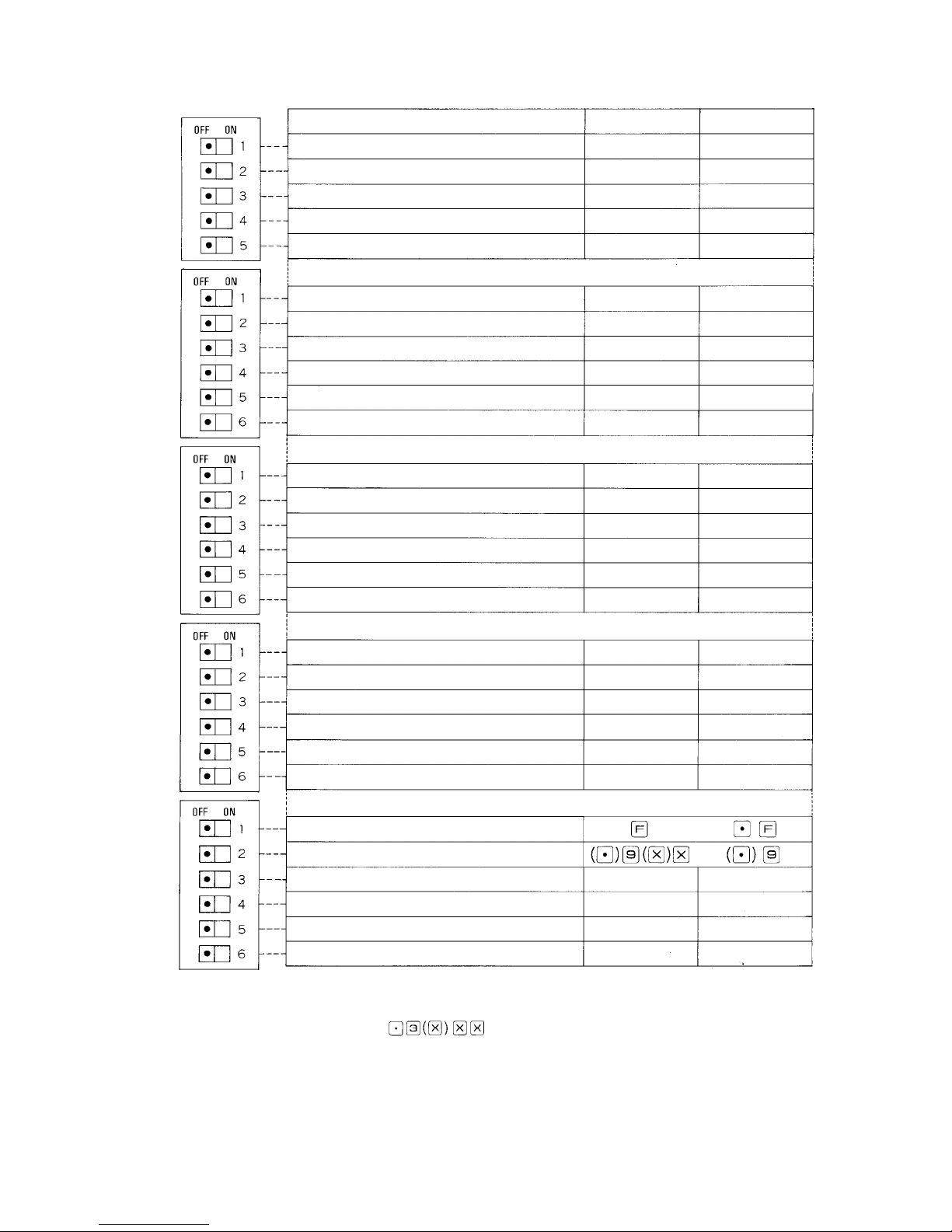
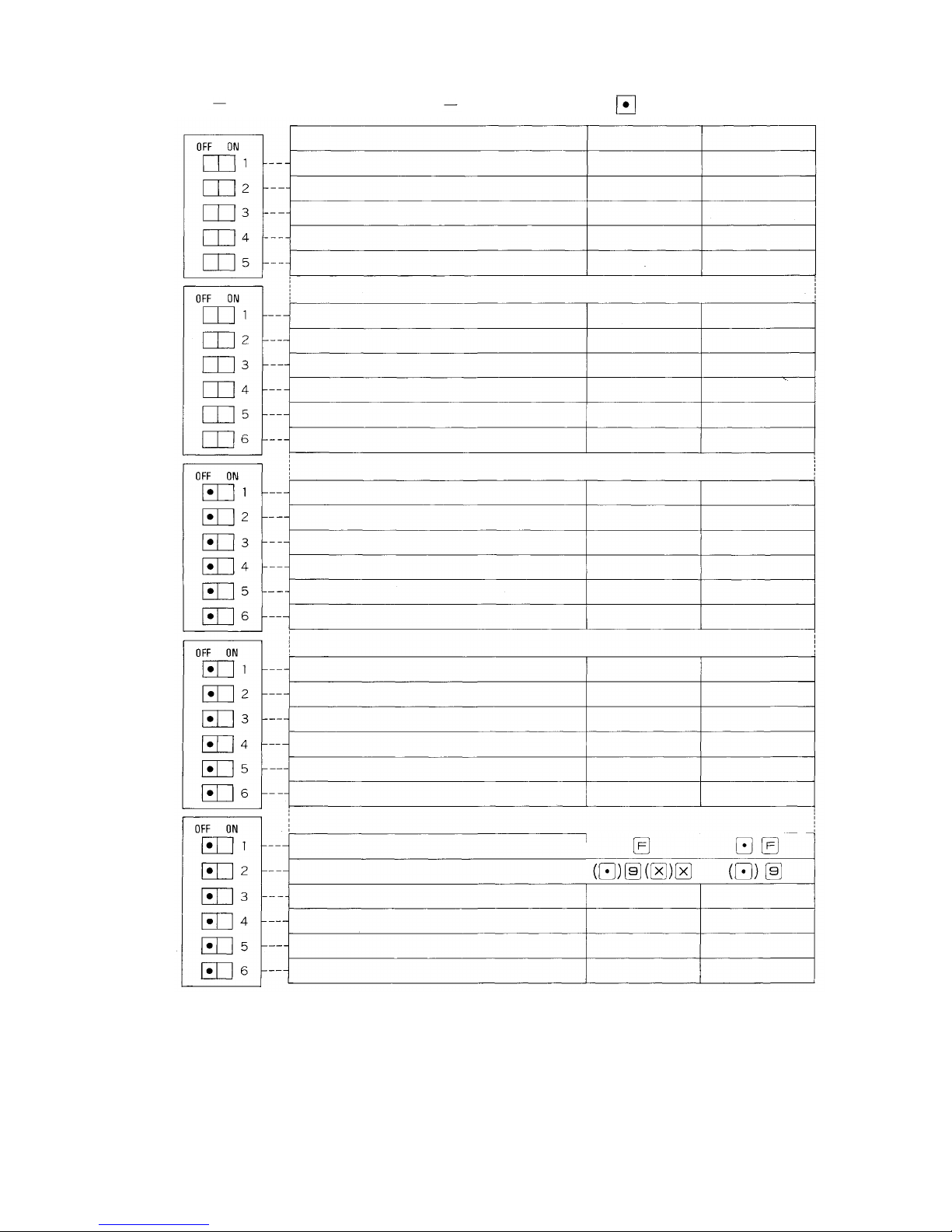
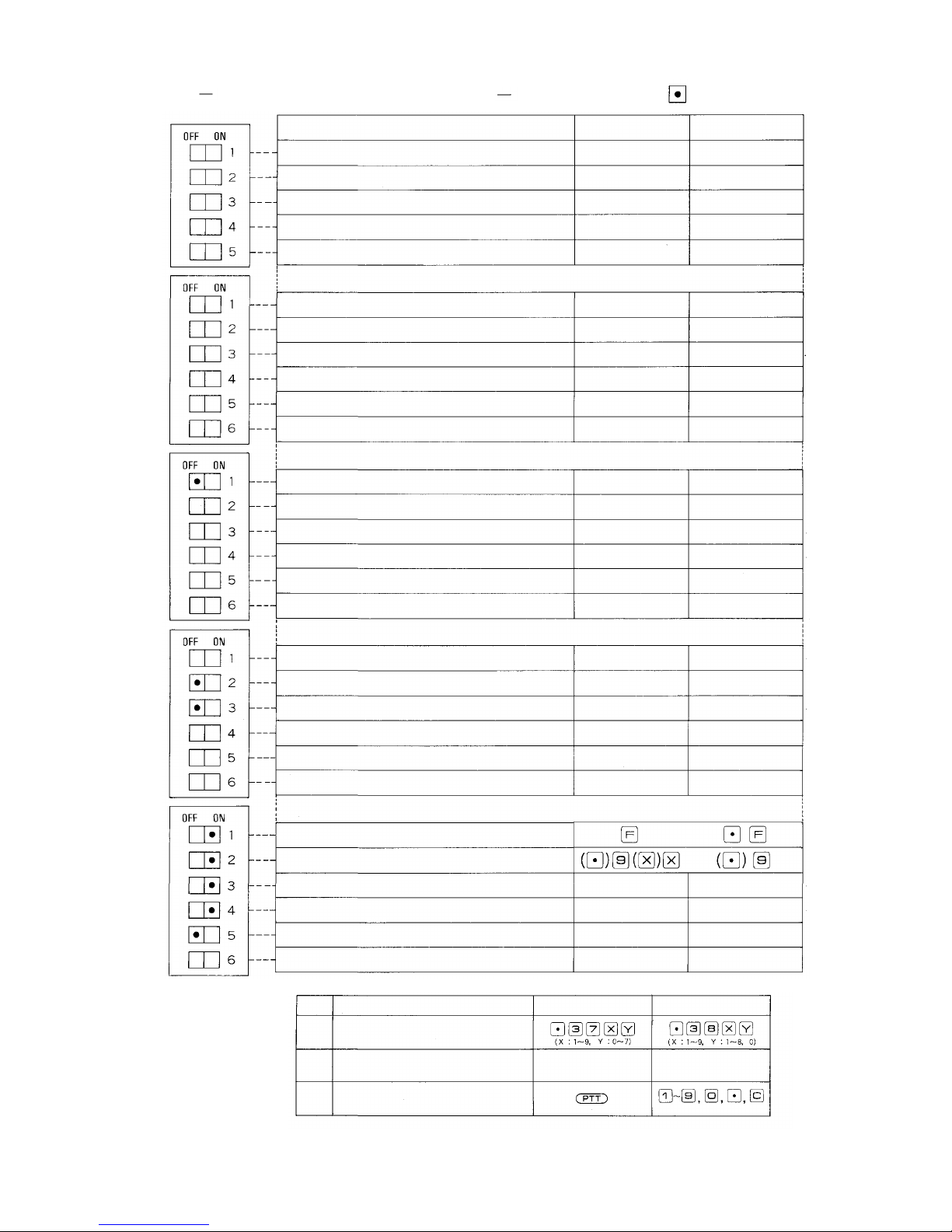
4. CP-62 DIP SWITCHES FOR FUNCTION SELECTION
SW-A
SW-B
SW-C
Functions
Link Selection; Link No. 0 ~ 3
Link Selection; Link No. 4 ~ 7
Link Selection; Link No. 8 ~ 11
Link Selection; Link No. 12 ~ 15
Time Interval Adjustment before Paging
Pre-announcement tone
Conference
Call Transfer, Paging During Normal Call
Priority & Executive Priority
Paging
Secretary Transfer, Group Hunting
System Size Selection
Selectable Numbering Schedules
Emergency All-Call
Paging Priority
Combination Paging
15 Individual Paging Zones
2-Digit Dialing
Switch OFF
Not Activate
Not Activate
Not Activate
Not Activate
None
Not Activate
Not Activate
Not Activate
Not Activate
Not Activate
EX-610
No.200 (20)~
Not Activate
Not Activate
Not Activate
7 Zones
3 Digit
Switch ON
Activate
Activate
Activate
Activate
1 sec
Activate
Activate
Activate
Activate
Activate
EX-620
No.100 (1 0 )~
Activate
Activate
Activate
15 Zones
2 Digit
*1
*1
*1
*1
*1
SW-D
SW-E
Stations Allowed Access to All Call, Conference
and General Purpose Control
Call Forwarding
Personal Number-Paging/Calling
Group Blocking
Programmable Station Numbering
Pager
Not Activate
Not Activate
P.No.Calling
Not Activate
Not Activate
Not Activate
Selectable Function Code
Selectable Dial Operation for Paging Response
Output Capacity of General Purpose Control
Memory of Calling Party Indication (Lamp type)
Tone of Called Mode at Privacy Sw. ON
Continuous Calling Tone (No. 200 Programming)
Note:
*1 Be
sure
to
place
the
SW-B-4
(Paging)
functions are used.
*2 Selection of "Large" adds 1 more digit to the number operated.
Example:
*3 When set to the "Active" position, the lamp continues to light to indicate all the stations that
initiate calls to the called stations in the "Privacy" or "Busy" mode.
*4 Place the DIP switch in "OFF" position if the system to be used is of "PV" type, in "ON"
position if "NP" type.
switch
Small
Without memory
Privacy
Not Activate
in the ON
position
when
Paging
Activate
Activate
P.No.Paging
Activate
Activate
Activate
Large
With memory
Continuous calling
Activate
and its
allied
*1
*1
*2
*3
*4
— 8 —
Page 10
Remarks
1. DIP
Switch
Positions
as the CPU-52A of EXES-5000
to
Turn
out the
Same
Functions
SW-A
SW-B
SW-C
Standard Hands-free Intercom System
Functions
Link Selection; Link No. 0 ~ 3
Link Selection; Link No. 4 ~ 7
Link Selection; Link No. 8 ~ 11
Link Selection; Link No. 12 ~ 15
Time Interval Adjustment before Paging
Pre-announcement tone
Conference
Call Transfer, Paging During Normal Call
Priority & Executive Priority
Paging
Secretary Transfer, Group Hunting
System Size Selection
Selectable Numbering Schedules
Emergency All-Call
Paging Priority
Combination Paging
15 Individual Paging Zones
2-Digit Dialing
Place the DIP Switches in the
Not Activate
Not Activate
Not Activate
Not Activate
None
Not Activate
Not Activate
Not Activate
Not Activate
Not Activate
EX-610
No.200 (20)~
Not Activate
Not Activate
Not Activate
7 Zones
3 Digit
Positions as follows.
Switch OFF
Switch ON
Activate
Activate
Activate
Activate
1 sec
Activate
Activate
Activate
Activate
Activate
EX-620
No. 100
Activate
Activate
Activate
15 Zones
2 Digit
*1
(10)~
*1
*1
*1
*1
SW-D
SW-E
Stations Allowed Access to All Call, Conference
and General Purpose Control
Call Forwarding
Personal Number-Paging/Calling
Group Blocking
Programmable Station Numbering
Pager
Selectable Function Code
Selectable Dial Operation for Paging Response
Output Capacity of General Purpose Control
Memory of Calling Party Indication (Lamp type)
Tone of Called Mode at Privacy Sw. ON
Continuous Calling Tone (No. 200 Programming)
Not Activate
Not Activate
P.No.Calling
Not Activate
Not Activate
Not Activate
Small
Without memory
Privacy
Not Activate
Activate
Activate
P.No.Paging
Activate
Activate
Activate
Large
With memory
Continuous calling
Activate
*1
*1
*2
*3
*4
— 9 —
Page 11
Remarks 2. DIP Switch Positions to turn out the Same Functions
as the CPU-55 of EXES-5000
SW-A
SW-B
SW-C
Hands-free Intercom System with Multi Functions
Functions
Link Selection; Link No. 0 ~ 3
Link Selection; Link No. 4 ~ 7
Link Selection; Link No. 8 ~ 11
Link Selection; Link No. 12 ~ 15
Time Interval Adjustment before Paging
Pre-announcement tone
Conference
Call Transfer, Paging During Normal Call
Priority & Executive Priority
Paging
Secretary Transfer, Group Hunting
System Size Selection
Selectable Numbering Schedules
Emergency All-Call
Paging Priority
Combination Paging
15 Individual Paging Zones
2-Digit Dialing
Place the DIP Switches in the
Switch OFF
Not Activate
Not Activate
Not Activate
Not Activate
None
Not Activate
Not Activate
Not Activate
Not Activate
Not Activate
EX-610
No.200 (20)~
Not Activate
Not Activate
Not Activate
7 Zones
3 Digit
Positions as follows.
Switch ON
Activate
Activate
Activate
Activate
1 sec
Activate
Activate
Activate
Activate
Activate
EX-620
No.100 (10)~
Activate
Activate
Activate
15 Zones
2 Digit
*1
*1
*1
*1
*1
SW-D
SW-E
Stations Allowed Access to All Call, Conference
and General Purpose Control
Call Forwarding
Personal Number-Paging/Calling
Group Blocking
Programmable Station Numbering
Pager
Not Activate
Not Activate
P.No.Calling
Not Activate
Not Activate
Not Activate
Selectable Function Code
Selectable Dial Operation for Paging Response
Output Capacity of General Purpose Control
Memory of Calling Party Indication (Lamp type)
Tone of Called Mode at Privacy Sw. ON
Continuous Calling Tone (No. 200 Programming)
Note: Following specification changes have been made from the CPU-55 to the CP-62.
Function
8 Selectable Make Output
*1
*2
*3
(9 units)
Calling Party Indication (Numerical Type)
The Station having a Indication Board
Continuous Calling Tone
One-touch Response
Small
Without memory
Privacy
Not Activate
CPU-55
Np. 200 ~ 231
No. 201 ~ 232
Activate
Activate
P.No.Paging
Activate
Activate
Activate
Large
With memory
Continuous calling
Activate
CP-62
*1
*1
*2
*3
*
4
— 10 —
Page 12
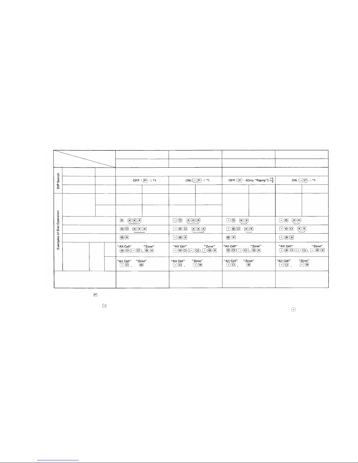
5. SETTING DIP SWITCH POSITIONS FOR FOUR (4) DIFFERENT TYPES OF DIAL OPERATION
The EXES-6000 system incorporating the CP-62 enables you to select the most suitable Numbering Schedule and Dial Operation of functions,
depending on th e Number of stations and on the functions required for t he system.
2-Digit Dialing
Selectable Function
Code
Selectable Numbering
Schedules
Numbering Schedules
SW-C-6
SW-E-1
SW-C-1
Hardwired
Station No.
Programmed
Station No.
Conference
Single Digit Registration
Paging Call
Comparison with the EXES-5000
Item
Type and Feature
of Dial Operation
Type 1
3-Digit Dialing, Standard
Type 2
3-Digit Dialing, Prog. St. No.
Type 3
2-Digit Dialing, Paging mainly
Type 4
2-Digit Dialing, 90 Station s
OFF (3-Digit Dialing)
ON (2-Digit Diali ng)
OFF
(200
(20))
No.200~327
No.200~399
ON
(100
(10))
*3
No.100~227
No.100~399
OFF
(200
(20))
No.200~327
No.200~999
ON (100(10)) *3
No.100~227
No.100~999
OFF
(200
(20))
No. 20~79
(60 Stations)
ON
(100
(10))
*3
No. 10~79
(70 Stations)
OFF
(200
(20))
No.20~99
(80 Stations)
ON
(100
(10))
*3
No.10~99
(90 Stations)
More functions but same easy dial
operation as the CPU-52A permits.
3-Digit Dial Operation allowed by
the CPU-55. Used when "Programmable Station Numbering"
in necessary.
New typ e which gives an easier
access to Station Calling and
Paging in Dialing .
2-Digit Dial Operation a llowed by
the CPU-55.
*4 In the
case
the DIP
Switch
is
selected
for
"Without
Zone
Number
(SW-E-2:
ON)", the Programming at No.200 Station for "Paging Zone Registration
(Function Code 70)" is essential in order to operate Paging Response to a
Zone Paging.
*5 Key operations for "General Purpose Control" always require dialing in
the first place of each function dial operation regardless of the position of
the DIP Switch SW-E-1.
*6 Refer to our "Functions & Operating Instructions fo r EXES-6000 CP-62" as
to dial operations for each function.
Note:
*1 In t he above table , means a numerical dial number.
*2 In the case the DIP Switch SW-E-1 for "Selectable Function Code" is placed
to OFF pos ition while the SW-C-6 for "2-digit Dialing" is in ON position,
you
cannot
omit
dialing
in
each
function
dial operation
except
the
cases
for "Paging" and "Paging Response".
*3 in the case th e DIP Switch SW-C-1 for "Selectable Numbering Schedules" is
turned to ON position "No.100 (10)", both of the "Personal Number Call"
and "Personal Number Paging" cannot be operated.
Paging
Response
SW-E-2
OFF
ON
*4
— 11 —
Page 13
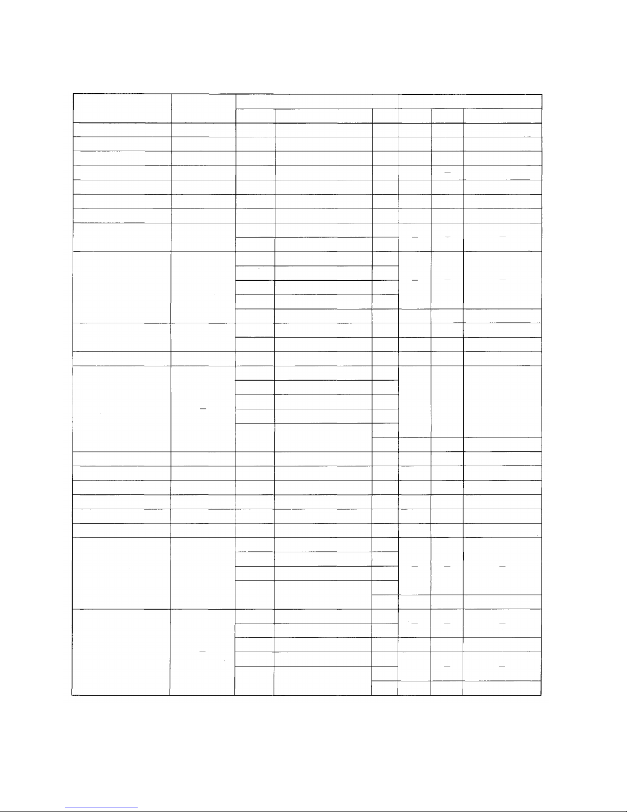
6. DIP SWITCH SELECTION AND STATION NO. 200 PROGRAMMING
FOR EACH FUNCTION
No.200 Programming should be proceeded in the following manner.
1. Write down the required data in "9. Programming Data Table (Page 39 ~ 45)".
2. Carry out the registration according to "7. Function Code Table for Station No.200 Programming (Page 15 ~ 17)" and
"8. Station No.200 Programming for Each Function (Page 18 ~ 38)".
Function
Single Digit Dialing
Automatic Access to Paging
Master/Sub Relationship
Privacy
Continuous Calling Tone
at Privacy Mode
Continuous Calling Tone
One-touch Response
Press-To-Talk Control
Personal Number Call
Personal Number Paging
Remote Response
Call Transfer
Paging during Normal Call
Group Hunting
Secretary Transfer
Call Forwarding
Priority
Executive Priority
Conference
Paging
Combination Paging
Registration or
Operation at
Each Station
Single Digit Registration
Single Digit Registration
-
Privacy SW.ON
Privacy SW.ON
-
-
Personal Number
Registration
Per sonal Number
Registration
Remote Response
Registration
-
-
Privacy SW.ON
Call Forwarding
Registration
-
-
-
-
No.
-
-
-
SW-E-5
SW-E-5
SW-E-6
SW-C-5
SW-C-1
SW-D-3
SW-B-4
SW-A-5
SW-C-1
SW-C-5
SW-E-2
SW-E-5
or SW-E-6
SW-B-2
SW-B-2
SW-B-4
SW-A-5
SW-C-5
SW-E-2
SW-B-5
SW-B-5
SW-D-2
SW-B-3
SW-B-3
SW-B-1
SW-B-4
SW-A-5
SW-C-5
SW-E-2
SW-B-4
SW-A-5
SW-C-4
SW-C-5
SW-E-2
CP DIP Switch
Function
-
-
-
Ton e of C alle d Mode
at Privacy SW.ON
Tone of Called Mode
at Privacy SW.ON
Continuous Calling Tone
15 Individual Paging Zones
Sele ctab le Numbering Schedules
Personal Number Paging
Paging
Time Interval Adjustment before
Paging Pre-announce Tone
Selectable Numbering Sche dul es
15 Individual Paging Zones
Select able Dial Operation
for Paging Response
Ton e of Cal led Mode at
Privacy SW.ON
or Continuous Calling Tone
Call Transfer, Paging during
Normal Call
Call Transfer, Paging during
Normal Call
Paging
Time Interval Adjustment before
Paging Pre-announce Tone
15 Individual Paging Zones
Selectable Dial Operation
for Paging Response
Secretary Transfer, Group Hunting
Secretary Transfer, Group Hunting
Call Forwarding
Priority & Executive Priority
Priority & Executive Priority
Conference
Paging
Time Interval Adjustment bef ore
Paging Pre-announce Tone
15 Individual Paging Zones
Selectable Dial Operation
for Paging Response
Paging
Time Interval Adjustment before
Paging Pre-announcement Tone
Combination Paging
15 Individual Paging Zones
Selectable Dial Operation
for Paging Response
ON/OFF
-
-
-
OFF
ON
ON
OFF
OFF
OFF
ON
ON/OFF
OFF
ON/OFF
ON
ON
ON
ON
ON
ON
ON/OFF
ON/OFF
OFF
ON
ON
ON
ON
ON
ON
ON
ON
ON/OFF
ON/OFF
OFF
ON
ON
ON/OFF
ON
ON/OFF
OFF
ON
Function
Group
-
A
B
-
-
A
-
C
A
-
C
B
B
-
-
A
-
C
D
-
C
No. 200 Programning
Function
Code
-
54
61
-
51
-
70
51
-
70
62
60
-
-
50
-
70
80
70
Function
-
Automatic Access to Paging
Master/Sub Relationship
-
-
Continuous Calling Tone
-
Paging Zone
Continuous Calling Tone
-
-
Paging Zone
Group Hunting
Secretary Transfer
-
-
Executive Priority
-
Paging Zone
Combination Paging
Paging Zone
— 12 —
Page 14
Function
Emergency All-call Paging
Paging Priority
(Z one No . 1 ~ 7 )
Type 1
Dialing
3-Digit
Type 2
Operation
Dial
and
Schedules
Type 3
Numbering
Only Paging
Dialing
2-Digit
Type 4
Output Capacity of
General Purpose Control
Programmable Station Numbering
Group Blocking
No.
200~
No.
100~
No.
200~
No.
100—
No.
20~
No.
10~
No.
20~
No.
10~
Registration or
Operation at
Each Station
-
-
-
-
-
-
-
-
-
-
-
-
No.
SW-B-4
SW-C-2
SW-C-5
SW-B-4
SW-A-5
SW-C-3
SW-C-5
SW-E-2
SW-C-6
SW-E-1
SW-C-1
SW-C-6
SW-E-1
SW-C-1
SW-C-6
SW-E-1
SW-C-1
SW-C-6
SW-E-1
SW-C-1
SW-C-6
SW-E-1
SW-C-1
SW-C-6
SW-E-1
SW-C-1
SW-C-6
SW-E-1
SW-C-1
SW-C-6
SW-E-1
SW-C-1
SW-E-3
SW-D-5
SW-D-4
CP DIP Switch
Function
Paging Zone
Emergency All-call Paging
15 Individual Paging Zones
Paging
Time Interval Adjustment before
Paging Pre-announce Tone
Paging Priority
15 Individual Paging Zon es
Selectable Dial Operation
for Paging Response
2-Digit Dialing
Selectable Function Co de
Sel ect ab le Numbering Schedules
2-Digit Dialing
Selectable Function C ode
Sele ctab le Numbering Schedules
2-Dig it Dialing
Selec table Function Code
Selectable Numbering Schedules
2-Digit Dialing
Selectable Function C ode
Selectable Numbering Schedules
2-Digit Dialing
Sele cta ble Function Code
Sel ecta ble Numbering Schedules
2-Digit Dialing
Selectable Function Code
Selectable Numbering Schedules
2-Digit Dialing
Selectable Function Cod e
Sel ect ab le Numbering Schedules
2-Digit Dialing
Selectable Function Cod e
Selectable Numbering Schedules
Output Capacity of
General Purpose Control
Programmable Station Numbering
Group Blocking
ON/OFF
ON
ON
ON/OFF
ON
OFF
ON
ON/OFF
OFF
ON
OFF
OFF
OFF
OFF
OFF
ON
OFF
ON
OFF
OFF
ON
ON
ON
OFF
OFF
ON
OFF
ON
ON
ON
OFF
ON
ON
ON
ON/OFF
ON
ON
Function
Group
-
C
C
-
E
C
D
D
No. 200 Programning
Function
Code
-
-
Paging Zone (No. 1 ~ 7)
Paging Zone (No.8 ~ 15)
Programmable Station
Numbering
Establishment of
Each Groups
Allowing Call s
among Groups
Allowing Acess to
Paging Zones
70
70
90
71
81
82
Function
-
-
— 13 —
Page 15
Function
Programmable
Restricted Access
for Stations
Selecti on of Calling Tone
Selection of Paging Pre-announce
Tone Duration
Time-out of Con versation
Time-out of Paging Call
In/Out Annunciation
Destination indication
Calling Party Indication
(Lamp Type)
Pager
Registration or
Operation at
Each Station
No.
SW-D-1
SW-C-1
SW-C-1
SW-E-4
SW-D-6
CP DIP Switch
Function
Stations Allowed
Access to All Call,
Conference and
General Purpose
Control
Sel ecta ble Numbering Schedules
Selectable Numbering Schedules
Memory of Calling Party Indication
(Lamp Type)
Pager
ON/OFF
ON
OFF
OFF
ON/OFFONC
Function
Group
A
A
A
A
A
A
No. 200 Programing
Function
Code
52
53
56
57
58
59
41
42
45
46
72
Function
Stations Allowd Access to
All Ca ll
Stations Allowed Acces to
Conference
Stations Allowed Access to
One-shot Make Output
Stations Allowed Access to
Make/Break Output
Stations Allowed Access to
8 Selectable (One-Shot Make)
/Decimal Output
Station Allowed Access
to 4 Decimal
Digits Output
Selection of Calling Tone
Selection of Paging
Pre-announce Tone Durat ion
Time-out of Conversation
Time-out of Paging Call
Group of Calling
Indication
Party
— 14 —
Page 16
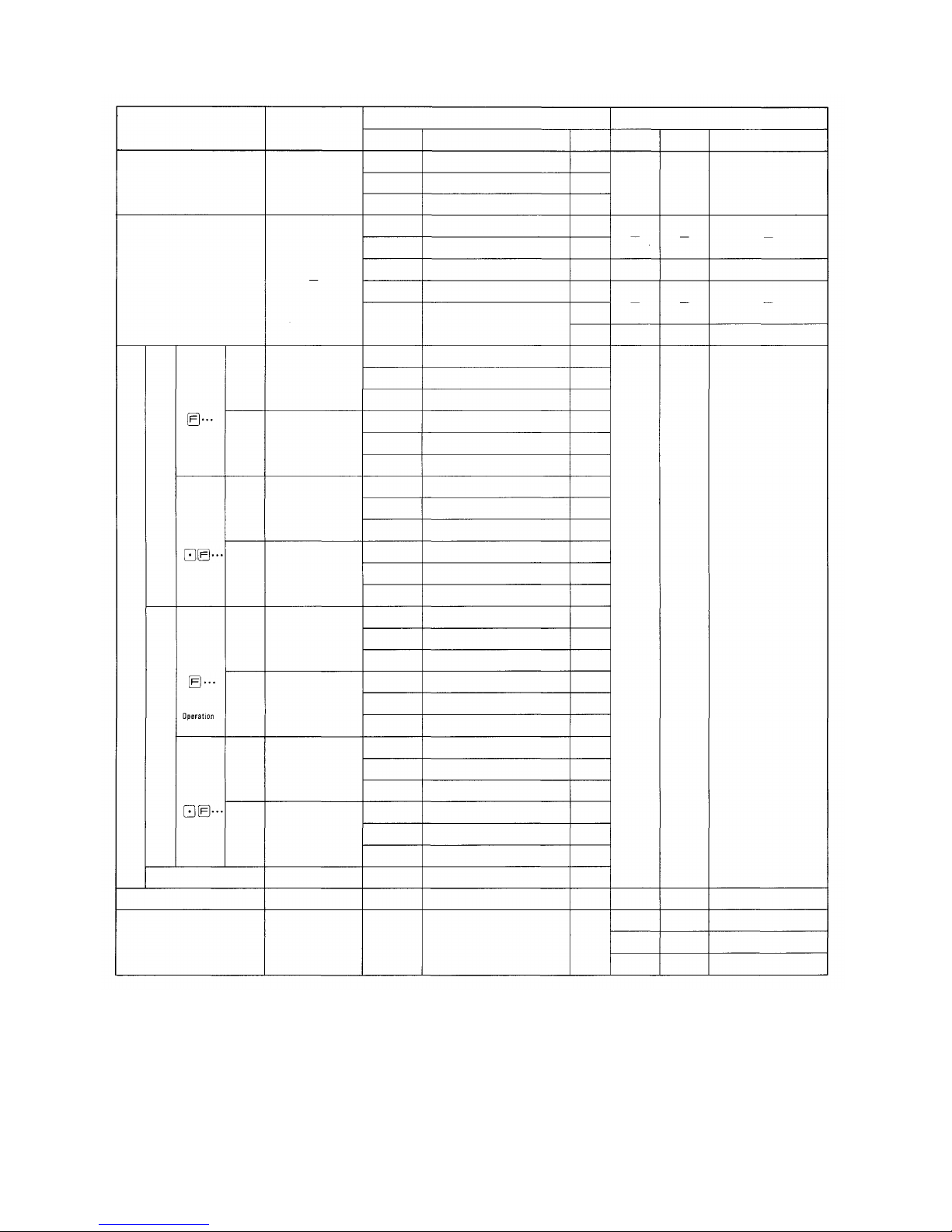
7. FUNCTION CODE TABLE FOR STATION NO. 200 PROGRAMMING
A. Clearance at one time
Function
Group
S
A
B
C
D
E
Function
Selection of Calling
Tone
Selection of Paging
Pre-announcement Tone
Time-out of
Conversation
Time-out of Paging
Call
Executive Priority
Continuous Calling
Tone
Station Allowed
Access to All Call
Stations Allowed
Access to Conference
Automatic Access to
Paging
Stations Allowed
Access to One Shot
Make Output
Stations Allowed
Access to Make/
Brake Output
Stations Allowed
Access to 8 Selectable/
Decimal Output
Stations Allowed
Access to 4 Decimal
Digits Output
Secretary Transfer
Master/Sub
Group Hunting
Paging Responce,
Paging Priori ty
Group Blocking of
Each Group
Group of Calling
Party Indication
Combination Paging
Group Blocking:
Allowing Calls
Among Groups
Group Blocking:
Allowing Access
to Paging Zones
Programable Station
Numbering
Personal Number
Single Digit Dialing
Remote Response
Function
Code
41
42
45
46
50
51
52
53
54
56
57
58
59
60
61
62
70
71
72
80
81
82
90
-
Note: *Can be registered at each station.
Clearance of Function
Function Registration on All Stations
Clearance of Function by Function Group
(Clears function group S)
(Clears function group A)
Confir-
mation
tone
Confirmation
tone
Confirmation
tone
Confirmation
tone
(Clears function group B)
Confirmation
tone
(Clears function group C)
Confirmation
tone
(Clears function group D)
Confirmation
tone
(Clears function group E)
Confirmation
tone
(Clears functions of Personal
No., Single Digit Dialing and
Remote Response)
Confirmation
tone
Confirmation
tone
Confirmation
tone
Confirmation
tone
Confirmation
tone
Confirmation
tone
Confirmation
tone
Confirmation
tone
Confirmation
tone
— 15 —
Page 17
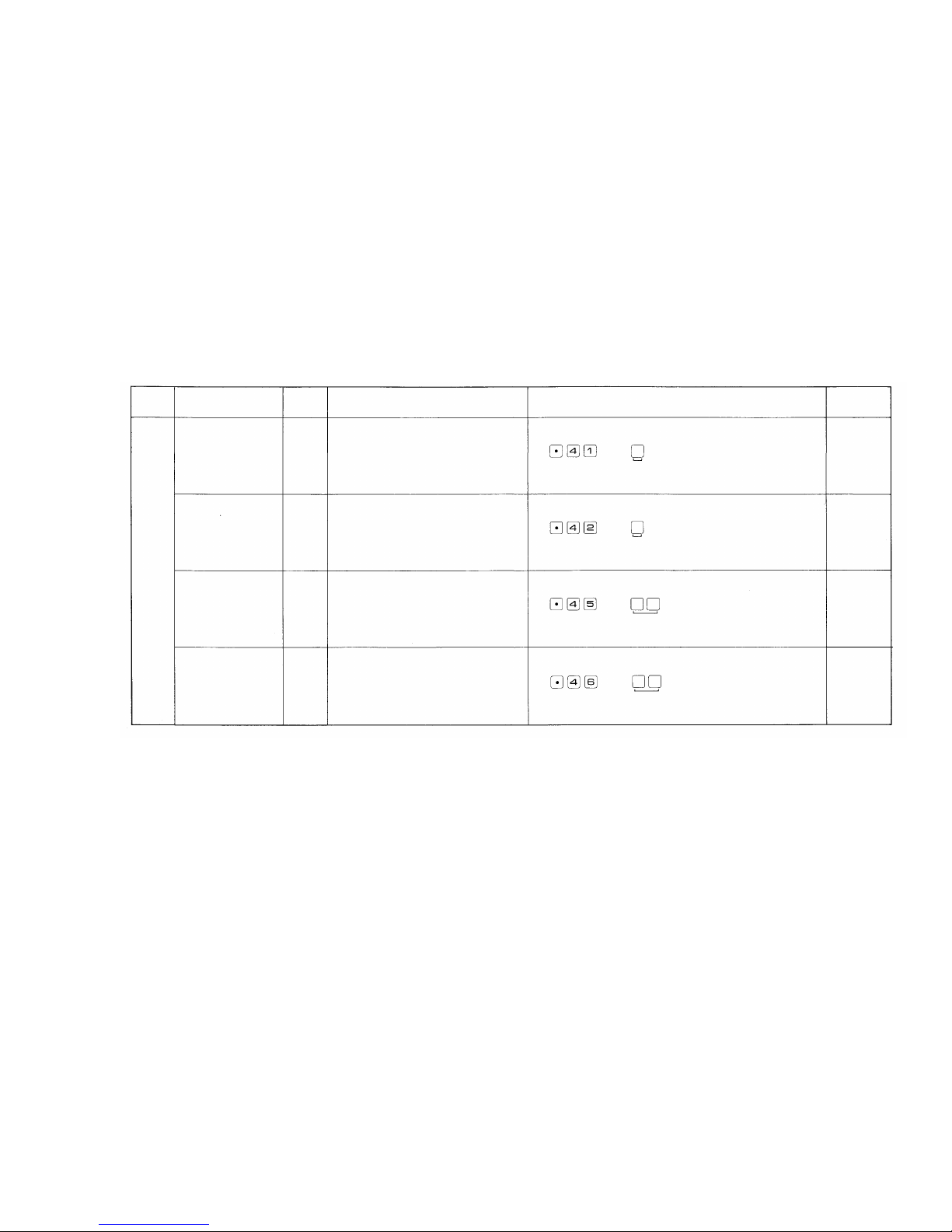
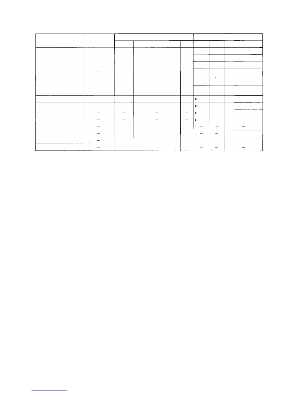
FUNCTION CODE TABLE FOR STATION NO. 200 PROGRAMMING
B. Programming of System
Function
Group
S
Function
Selection of Calling Tone
Selection of Paging
Pre-announcement
Tone Duration
Time-out of Conversation
Time-out of Paging Call
Function
Code
41
42
43
44
Remarks
Two different calling tones, single note tone or
trill
note
tone,
are
available
in
selection
for
the Hands-free syst em except the continuous
calling tone.
You c an select the length of time of paging
pre-announcement tone.
Stations can be disconnected automatically
from the speech path in the unit of Minute and
the Hurry-up Signal Tone can be heard 10
seconds before the disconnection.
Stations can be disconnected a utomatically
from the Paging circuit in the unit of Minute
and the Hurry-up Signal Ton e can be heard 10
seconds bef ore the disconnection.
Initially
Programmed
Mode
Trill note Tone
(0.3
sec.)
Paging
Pre-announce-
ment To ne
(2
sec.)
Without
Time-out
Without
Time-out
Operating for Programming
0: Without Calling Tone
1: Single Note Tone (0.2 sec.)
2: Trill note Tone (0.3 sec.)
0: Wit hout Paging Pre-announcement Tone.
1: Paging Pre-announcement To ne (1 sec.)
2: Paging Pre-announcement Tone (2 sec.)
00: Without Time-out function
01~99: Length limited (minute)
00: Without Time-out function
01~99: Length limited (minute)
— 16 —
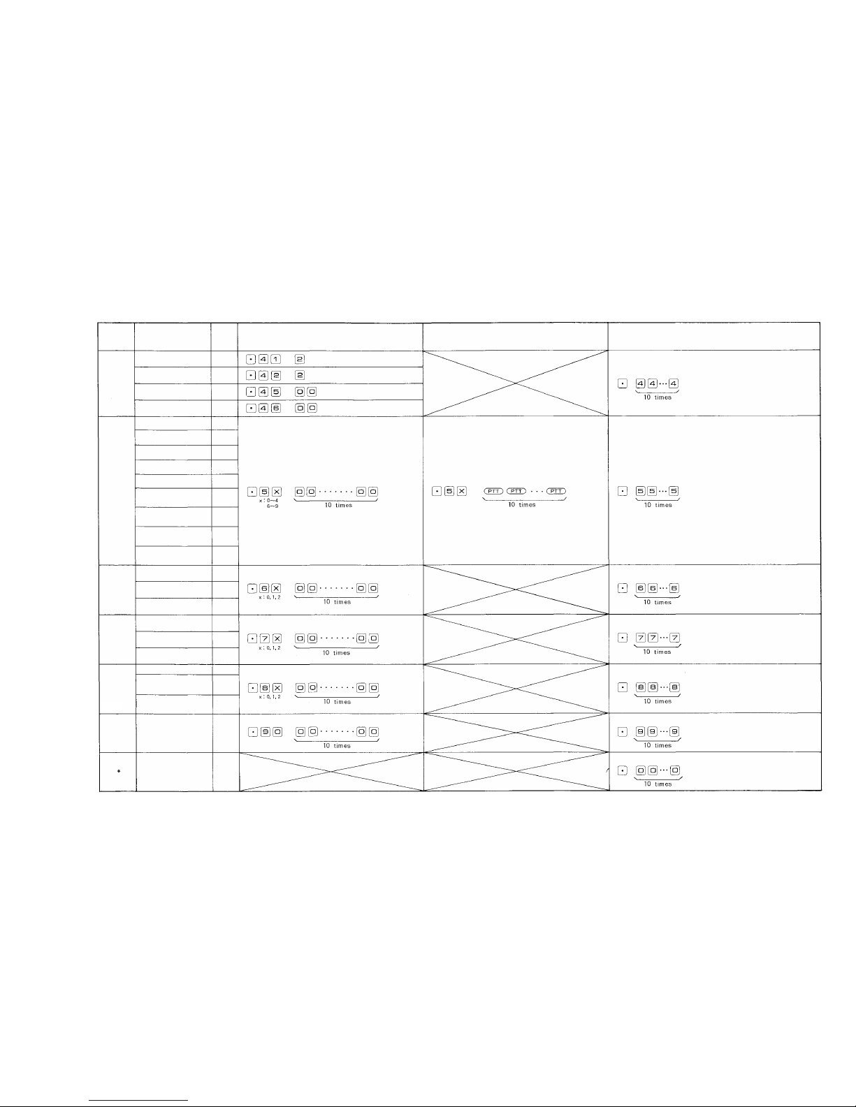
Page 18
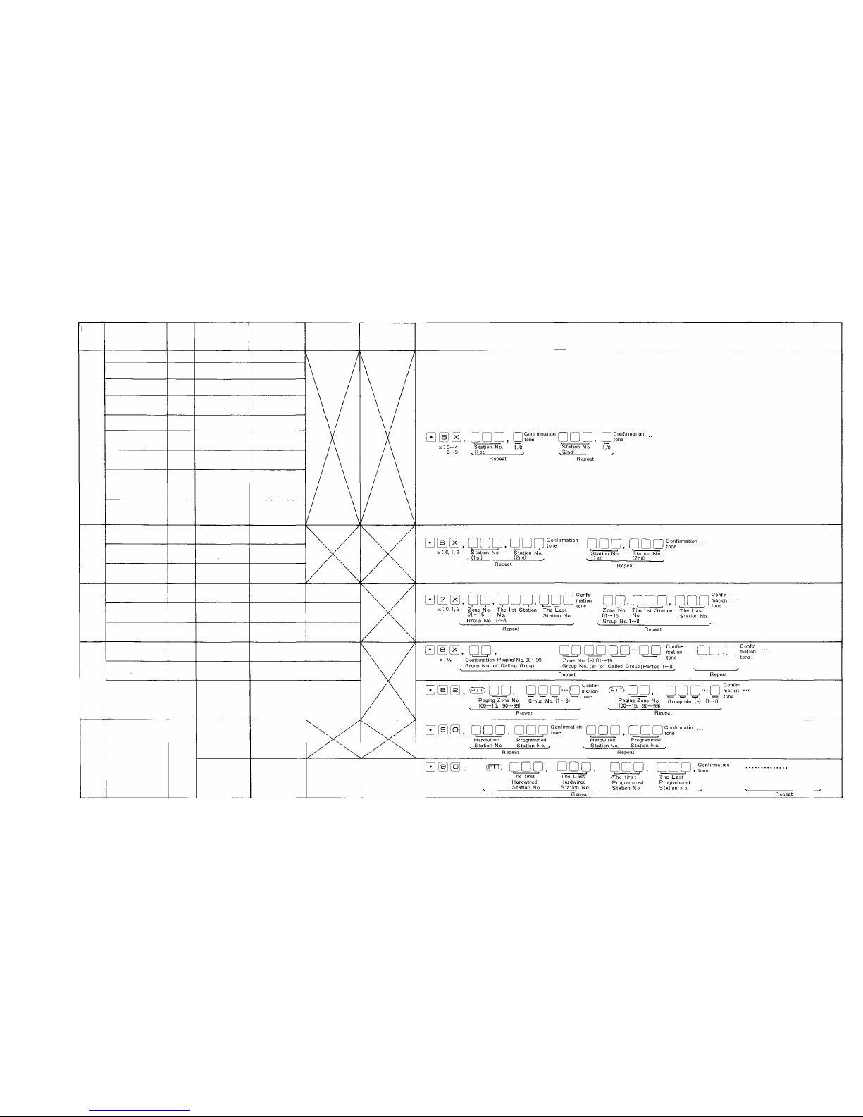
FUNCTION CODE TABLE FOR STATION NO. 200 PROGRAMMING
C. Programming of each Function
*1
Station
No.'s
except
Programmed
Station
No.'s
are
Hardwired
Station
No.'s
No.200~327/No.100~227/No.20~99/No.
10-99.
*2
Programmed
Station
No.'
s are
No.200~999/No.100~999/No.20~99/No.
10-99.
3rd Parameter
4th Parameter
OPERATING FOR PROGRAMMING
Function
Group
A
B
C
Function
Executive Priority
Continuous Calling
Tone
Station Allowed
Access to All Call
Stations Allowed
Access to
Conference
Automatic Access to
Paging
Stations Allowed
Access to One Shot
Make Output
Stations Allowed
Access to Make/
Break Output
Stations Allowed
Access
to 8 Selectable
(One Shot Make)/
Decimal Output
Stations Allowed
Access to 4
Decimal Digits
Output
Secretary Transfer
Master/Sub
Group Hunting
Paging Zone
Group Blocking:
Establishment of
Each Group
Group of Calling
Party Indication
Function
Code
50
51
52
53
54
56
57
58
59
60
61
62
70
71
72
1st Parameter
Station No.
Station No.
Station No.
Station No.
Station No.
Station No.
Station No.
Station No.
Station No.
Executive
Station No.
Sub Station No.
Main station No.
Zone No. (01~15)
Group No. (1~8)
Group No. (1~8)
2nd Parameter
ON/OFF (1/0)
ON/OFF (1/0)
ON/OFF (1/0)
ON/OFF (1/0)
ON/OFF (1/0)
ON/OFF (1/0)
ON/OFF (1/0)
ON/OFF (1/0)
ON/OF F (1/0)
Secretary Station
No.
Master Station No.
Transfered Station
No.
The First Station
No. of the Zone
The First Station
No. of the Group
The First Station
No. of the Group
The Last Station
No. of the Zone
The Last Station
No. of the Group
The Last Statio n
No. of the Group
D
Combination Paging
Group Blocking:
Allowing Calls
Among Groups
Group Blocking:
Allowing Access
to Paging Zones
80
81
82
Combination
Zone No. (90~99)
Calling Group No.
(1~8)
Paging Zone No. of
Paged Group
(00~15, 90~99)
Zone No. (s) (01 ~ 15) (Plural)
Called Group No.(s) (1~8)
(Plural)
Paing Group No.(s) (1~8)
(Plural)
E
Programable
Station Numbering
90
Hardwired Station
No.
*2
The First
Hardwired
Station No.
*1
Programmed Sta-
tion No.
*2
The Last
Hardwired
Station No.
*1
The First
Programmed
Staion No.
*2
The Last
Programmed
Station No.
*2
— 17 —
Page 19
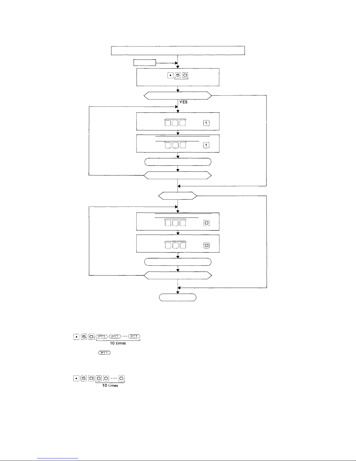
8. STATION NO. 200 PROGRAMMING FOR EACH FUNCTION
8-1 EXECUTIVE PRIORITY (FUNCTION CODE 50)
EXECUTIVE PRIORITY
STEP1
Touch
Function Code
New Registration?
Executive Station No.
Touch
Executive Station No.
Touch
Confirmation tone
NO
New Registration finished?
Executive Station No.
Touch
Executive Station No. OFF
Touch
Confirmation tone
YES
Release?
YES
NO
ON
ON
NO
OFF
NO
NOTES
1. To allow all the stations to have this function,
Touch
Be sure to depress the
keys steadily.
(Confirmation tone
will be heard.)
2. To release at one time the data programmed into all the
stations for this function,
Touch
(Confirmation tone
wil l be heard.)
Release finished?
YES
Return
3. Re-start at Step 1 when mis-dialing occures.
(All other registrations remain valid.)
4. Station No. should be 2 digits in length when 2 Digit Dialing
function is employed.
5. CP DIP switch B-3 must be "ON" to employ this function.
— 18 —
Page 20
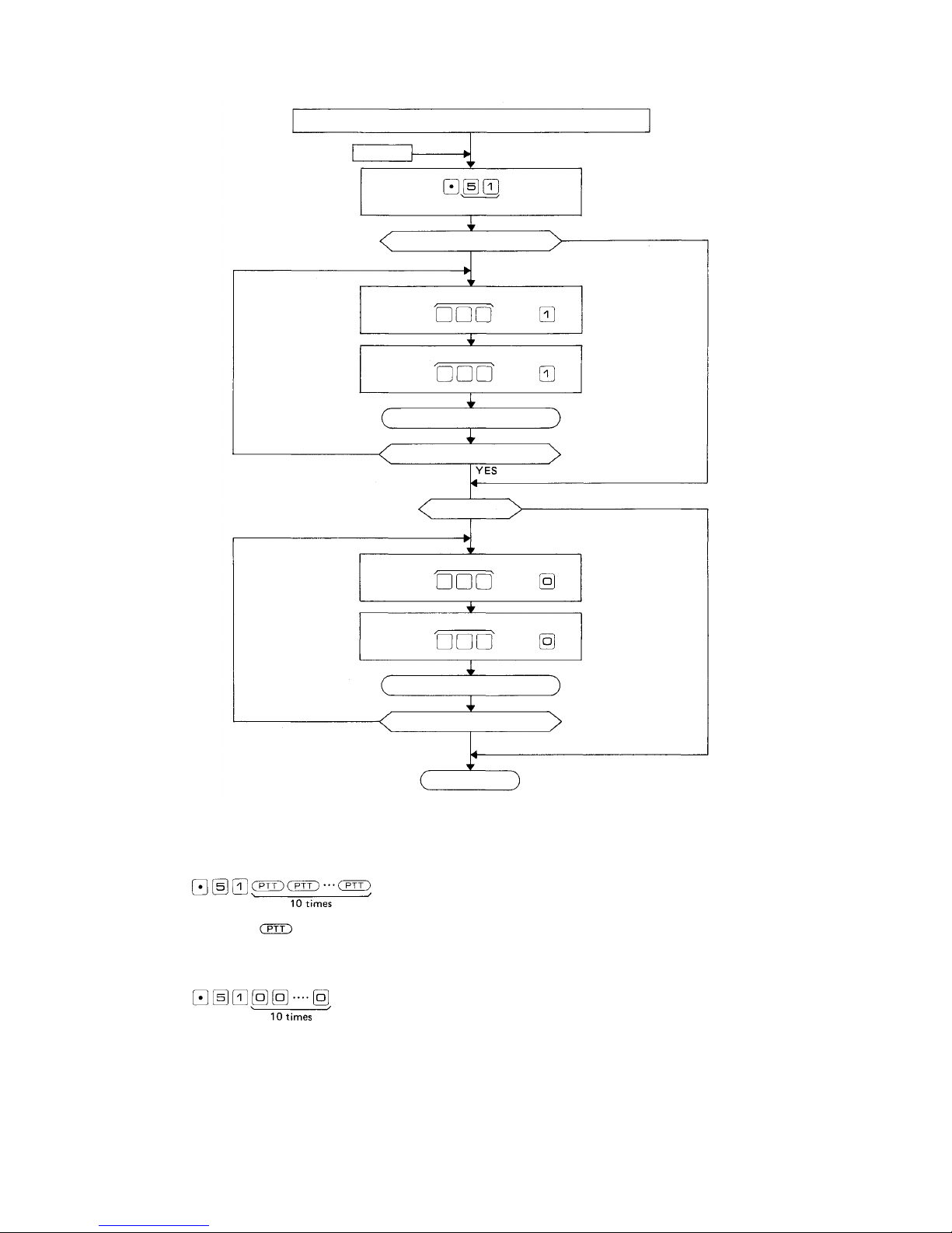
8-2 CONTINUOUS CALLING TONE (FUNCTION CODE 51)
CONTINUOUS CALLING TONE
STEP1
Touch
Function Code
New Registration?
YES
Continuously Called Station No. ON
Touch
Continuously Called Station No. ON
Touch
Confirmation tone
NO
New Registration finished?
Release?
YES
Continuously Called Station No. OFF
Touch
Continuously Called Station No.
Touch
Confirmation tone
NO
NO
OFF
NOTES
1. To allow all the stations to have this function,
Touch
the
keys steadily.
data
programmed
Be sure to depress the
2. To
release
at one
time
stations for this function,
Touch
(Confirmation tone
wil l be heard.)
NO
(Confirmation tone
will be heard.)
into
all the
Release finished?
YES
Return
3. Re-start at Step 1 when mis-dialing occures.
(All other registrations remain valid.)
4. Station No. should be 2 digits in length when 2 Digit Dialing
function is employed.
5. CP DIP switch E-6 must be "ON" to employ this function.
— 19 —
Page 21

8-3 STATIONS ALLOWED ACCESS TO ALL CALL (FUNCTION CODE 52)
STATIONS ALLOWED ACCESS TO ALL CALL
STEP1
Touch
Function Code
NO
New Registration?
YES
Allowed Station No. ON
Touch
Allowed Station No. ON
Touch
Confirmation tone
New Registration finished?
YES
Release?
YES
Allowed Station No. OFF
Touch
Allowed Station No. OFF
Touch
Confirmation tone
NO
NO
NO
NOTES
1. To allow all the stations to have this function,
Touch
Be sure to depress the
keys steadily.
(Confirmation tone
will be heard.)
2. To release at one time the data programmed into all the
stations for this function,
Touch
(Confirmation tone
will be heard.)
Release finished?
YES
Return
3. Re-start at Step 1 when mis-dialing occures.
(All other registrations remain valid.)
4. Station No. should be 2 digits in length w hen 2 Digit Dialing
function is employed.
5. Programming is necessary only if CP DIP switch D-1 is "ON".
— 20 —
Page 22

8-4 STATIONS ALLOWED ACCESS TO CONFERENCE (FUNCTION CODE 53)
STATIONS ALLOWED ACCESS TO CONFERENCE
STEP 1
Touch
NO
Allowed Station No. ON
Touch
Allowed Station No. ON
Touch
Confirmation tone
NO
NOTES
New Registration finished?
Touch
Touch
NO
1. To allow all the stations to have this function,
Touch
Be sure to depress the
keys steadily.
(Confirmation tone
will be heard.)
2. To release at one time the data programmed into all the
stations for this function,
Touch
(Confirmation tone
wil l be heard.)
YES
Release?
YES
Allowed Station No. O FF
Allowed Station No. OFF
Confirmation tone
Release finished?
YES
Return
NO
3. Re-start at Step 1 when mis-dialing occures.
(All other registrations remain valid.)
4. Station No. should be 2 digits in length when 2 Digit Dialing
function is employed.
5. Programming is necessary only if CP DIP switch D-1 is "ON".
Switch B-1 must be "ON" to employ this function.
— 21 —
Page 23

8-5 AUTOMATIC ACCESS TO PAGING (FUNCTION CODE 54)
HANDSET SUBSTATIONS ALLOWED ACCESS TO PAGING
STEP 1
Touch
Function Code
NO
New Registration?
YES
Allowed Station No. ON
Touch
Allowed Station No. ON
Touch
Confirmation tone
New Registration finished?
YES
Release?
YES
Allowed Station No. OFF
Touch
Allowed Station No. OFF
Touch
Confirmation tone
NO
NO
NO
NOTES
1. To allow all the stations to have this function,
Touch
Be sure to depress the
keys steadily.
(Confirmation tone
will be heard.)
2. To release at one time the data programmed into all the
stations for this function.
Touch
(Confirmation tone
wil l be heard.)
Release finished?
YES
Return
3. Re-start at Step 1 when mis-dialing occures.
(All other registrations remain valid.)
4. Station No. should be 2 digits in length when 2 Digit Dialing
function is employed.
— 22 —
Page 24

COMPLEMENTARY NOTES
(1) Automatic Access to Paging
This function facilitates Paging / Paging response from a
Substation TL-600S. Just picking up the Handset of Substation automatically activates Paging or Paging Response
mode.
(2) Required Programming for Automatic Access to Paging
from Handset Substation.
2-1) First, connect a Master Station HF-600M or TL-600M in place
of a Substation TL-600S.
2-2) Program at that station a necessary function for Single Digit
Dialing such as Paging, Paging Response, Personal Number Call
or
etc.
2-3) Then, replace the Master Station with a Substation TL-600S.
2-4) Program "Automatic Access to Paging fr om Handset Substation
(Function Code 54)" at the Station No. 200 according to the
programming instructions.
(5) Call by Dialing
Function
Single Digit
Dialing
& Picking up the Handset
Necessary
Programming
Single Digit
Registration
at Station
By dialing
at
HF-620S or
HF-600S
(3) Single Digit Dialing and Automatic Access to Paging
By programming "Single Digit Dialing" at any master station, a
single touch of the dial activates "Station Call", "Personal
Number Call", "Paging" or "Paging Response" mode. But in
using a TL-600S and a HF-600S, "Automatic Access to Paging
from Handset Substation" function cannot be adopted only by
programming "Single Digit Dialing" at the station. It also
reqires the programming for Function Code 54 at No. 200
Station.
(4) A call to Master Station from Handset or Hands-free/
Handset Substation
"Master/Sub Relationship (Function Code 61)" can be
programmed into Handset Substation TL-600S or Hands-free/
Handset Substation HF-600S etc., wh ere you can call the
relative Master Station by a single touch of the dial , or by
picking up the Handset.
In activating a mode with Hands-free/Handset Substation
HF-600S by picking up the Handset, "Privacy" switch on the
Station is to be "ON" position.
Call to Master Station
By picking up
Handset
at
TL-600S or
HF-600S
(Privacy SW. ON)
Paging Call, Paging Response
or Personal Number Call
By dialing
at
HF-620S or
HF-600S
By picking up
Handset
at
TL-600S or
HF-600S
(Privacy SW. ON)
Master/sub
Relationship
Automatic Acess to Paging
Paging (or Calling)
from Handset Substation
Programming at
Station No. 200
(Function Code 61)
1. Single Digit
Registration
at Station
2. Programming at
Station No.200
(Function Code 54)
Note.
Possible
Impossible
Possible but usually Not to be used
— 23 —
Page 25

8-6 STATIONS ALLOWED ACCESS TO ONE-SHOT MAKE OUTPUT (FUNCTION CODE 56)
STATION ALLOWED ACCESS TO ONE SHOT MAKE OUTPUT
STEP1
Function Code
Allowed Station No.
Touch
Allowed Station No. ON
Touch
Confirmation tone
NO
New Registration finished?
Allowed Station No. OFF
Touch
Allowed Station No. OFF
Touch
New Registration?
YES
YES
Release?
YES
Confirmation tone
NO
ON
NO
NO
NOTES
1. To allow all the stations to have this function,
Touch
Be sure to depress the
keys steadily.
(Confirmation tone
will be heard.)
2. To release at one time the data programmed into all the
stations for this function,
Touch
(Confirmation tone
will be heard.)
Release finished?
YES
Return
3. Re-start at Step 1 when mis-dialing occures.
(All other registrations remain valid.)
4. Station No. should be 2 digits in length when 2 Digit Dialing
function is employed.
5. Programming is necessary only if CP DIP switch D-1 is "ON".
— 24 —
Page 26

8-7 STATIONS ALLOWED ACCESS TO MAKE/BREAK OUTPUT (FUNCTION CODE 57)
STATIONS ALLOWED ACCESS TO MAKE/BREAK OUTPUT
STEP 1
Touch
Function Code
New Registration?
Allowed Station No. ON
Touch
Allowed Station No. ON
Touch
Confirmation tone
NO
New Registration finished?
Allowed Station No. OFF
Touch
Allowed Station No. OFF
Touch
Confirmation tone
YES
Release?
NO
NO
NO
NOTES
1. To allow all the stations to have this function,
Touch
Be sure to depress the
keys steadily.
(Confirmation tone
will be heard.)
2. To release at one time the data programmed into all the
stations for this function,
Touch
(Confirmation tone
will be heard.)
Release finished?
YES
Return
3. Re-start at Step 1 when mis-dialing occures.
{Al l other registrations remain valid.)
4. Station No. should be 2 digits in length when 2 Digit Dialing
function is employed.
5. Programming is necessary only if CP DIP switch D-1 is "ON".
— 25 —
Page 27

8-8 STATIONS ALLOWED ACCESS TO 8 SELECTABLE (ONE-SHOT MAKE) OR DECIMAL OUTPUT
(FUNCTION CODE 58)
STATIONS ALLOWED ACCESS TO 8 SELECTABLE
(ONE-SHOT MAKE) OR DECIMAL OUTPUT
STEP1
Touch
Function Code
New Registration?
Allowed Station No. ON
Touch
Allowed Station No. ON
Touch
Confirmation tone
New Registration finished?
YES
Release?
Allowed Station No. OFF
Touch
Allowed Station No. OFF
Touch
Confirmation tone
NO
NO
NO
NOTES
1. To allow all the stations to have this function,
Touch
Be sure to depress the
keys steadily.
(Confirmation tone
will be heard.)
2. To release at one time the data programmed into all the
stations for this function,
Touch
(Confirmation tone
will be heard.)
Release finished?
Return
3. Re-start at Step 1 when mis-dialing occures.
(All other registrations remain valid.)
4. Station No. should be 2 digits in length when 2 Digit Dialing
function is employed.
5. Programming is necessary only if CP DIP switch D-1 is "ON".
— 26 —
Page 28

8-9 STATIONS ALLOWED ACCESS TO 4 DECIMAL DIGITS OUTPUT (FUNCTION CODE 59)
STATIONS ALLOWED ACCESS TO 4 DECIMAL DIGITS OUTPUT
STEP 1
Touch
Function Code
New Registration?
Allowed Station No. ON
Touch
Allowed Station No. ON
Touch
Confirmation tone
NO
New Registration fi nished?
Allowed Station No. OFF
Touch
Allowed Station No. OFF
Touch
Confirmation tone
YES
YES
Release?
YES
NO
NO
NO
NOTES
1. To allow all the stations to have this function,
Touch
Be sure to depress t he
keys steadily.
(Confirmation tone
will be heard.)
2. To release at one time the data programmed into al l the
stations for this function,
Touch
(Confirmation tone
will be heard.)
Release finished?
YES
Return
3. Re-start at Step 1 when mis-dialing occures.
(All other registrations remain valid.)
4. Station No. should be 2 digits in length when 2 Digit Dialing
function is employed.
5. Programming is necessary only if CP DIP switch D-1 is "ON".
— 27 —
Page 29

8-10 SECRETARY TRANSFER (FUNCTION CODE 60)
SECRETARY TRANSFER
Step 1
Touch
Function Code
New Registration?
Executive Station No.
Touch
Executive Station No.
Touch
Confirmation tone
New Registration finished?
Secretary Station No.
Secretary Station No.
Release?
Executive Station No. Executive Station No.
Touch
Executive Station No. Executive Station No.
Touch
Confirmation tone
Release finished?
NOTES
1. To release at one time the data programmed into all the
stations for this function,
Touch
2. Re-start at Step 1 when mis-dialing occurs.
(All other registrations remain valid.)
(Confirmation tone
wil l be heard.)
Return
3. Station No. should be 2 digits in length when 2 Digit Dialing
function is employed.
4. Switch B-5 must be "ON" to employ this function.
5. Programming of Secretary Transfer can be made in a daisy
chain method. For their examples, refer to the following sketch.
— 28 —
Page 30

8-11 MASTER/SUB RELATIONSHIP (FUNCTION CODE 61)
MASTER/SUB RELATIONSHIP
Step 1
Touch
Function Code
New Registration?
YES
Sub Station No. Master S tatio n No.
Touch
Sub Station No. Master Station No.
Touch
Confirmation tone
NO
New Registration finished?
YES
Release?
YES
Sub Station No. Sub Station No.
Touch
Sub Station No. Sub Station No.
Touch
NO
NO
NO
NOTES
1. To release at one time the data programmed into all the
stations for this function,
Touch
(Confirmation tone
wil l be heard.)
2. Re-start at Step 1 when mis-dialing occurs.
(All other registrations remain valid.)
Confirmation tone
Release finished?
Return
3. Station No. should be 2 digits in length when 2 Digit Dialing
function is employed.
— 29 —
Page 31

8-12 GROUP HUNTING (FUNCTION CODE 62)
TRANSFERED STATION No. FOR GROUP HUNTING
Step 1
Touch
Original Station No. Transfered Station No.
Touch
Original Station No. Transfered Station No.
Touch
NO
New Registration finished?
Function Code
New Registration?
Confirmation tone
Release?
Original Station No. Original Station No.
Original Station No. Original Station No.
Touch
NOTES
1. To release at one time the data programmed into all the
stations for this function,
Touch
(Confirmation tone
will be heard.)
2. Re-start at Step 1 when mis-dialing occurs.
(All other registrations remain valid.)
Confirmation tone
Release finished?
Return
3. Station No. should be 2 digits in length when 2 Digit Dialing
function is employed.
4. Switch B-5 must be "ON" to employ this function.
5. Programming of Group Hunting can be made in a daisy chain
method. For their examples, refer to the following sketch.
— 30 —
Page 32

8-13 PAGING ZONE (FUNCTION CODE 70)
ESTABLISHMENT OF EACH PAGING ZONE
Step 1
Touch
Function Code
Paging Zone No.
(01 ~ 15)
Touch
Paging Zone No.
(01 ~ 15)
Touch
New Registration finished?
NOTES
1. To
release
at one
time
the
data
programmed
into
all the
Zones for this function,
Touch
(Confirmation tone
will be heard.)
2. Re-start at Step 1 when mis-dialing occurs.
(All other registrations remain valid.)
3. Station No. should be 2 digits in length when 2 Digit Dialing
function is employed.
1st Station No.
of the Zone
1st Station No.
of the Zone
Confirmation tone
Return
4. Switch B-4 must be "ON" to employ this function.
5. 2-Digit dialing is necessary even in the case of Zone No. 1
6. In the case "Paging Response Without Zone Number" mode
7. In the
Last Station No.
of the Zone
Last Statio n No.
of the Zone
to No. 7.
Ex. Zone No.2
is selected by the DIP Switch SW-E-2, th is
registration is essential.
case
"Paging
Priority"
function
is
adopted
by the DIP
Switch SW-C-3, this registration should be made for each
Paging Zone of No. 01 t o No. 07.
— 31 —
Page 33

8-14 GROUP BLOCKING 1 : ESTABLISHMENT OF EACH GROUP (FUNCTION CODE 71)
GROUP BLOCKING 1
ESTABLISHMENT OF EACH GROUP
Step 1
Touch
Function Code
Group No. 1st Station No. Last Station No.
(1~8) of the Zone of the Zone
Touch
Group No. 1st Station No. Last Station No.
(1~8) of the Zone of the Zone
Touch
Confirmation tone
NO
New Registration finished?
NOTES
1. To release at one time the data programmed into all the
groups for this function,
Touch
2. Re-start at Step 1 when mis-dialing occurs.
(All other registrations remain valid.)
(Confirmation tone
wil l be heard.)
Return
3. Station No. should be 2 digits in length when 2 Digit Dialing
function is employed.
4. CP DIP swit ch D-4 must be "ON" to employ this function.
— 32 —
Page 34

8-15 CALLING PARTY INDICATION (LAMP TYPE) (FUNCTION CODE 72)
ESTABLISHMENT OF EACH GROUP
Step 1
Touch
Function Code
Group No. 1st Station No. Last Station No.
(1 ~ 8) of the Zone of the Zone
Touch
Group No. 1st Station No. Last Station No.
(1 ~ 8) of the Zone of the Zone
Touch
Confirmation tone
NO
New Registration finished?
NOTES
1. To release at one time the data programmed into all the
groups for this function,
Touch
2. Re-start at Step 1 when mis-dialing occurs.
(Confirmation tone
will be heard.)
(Al l other registrations remain valid.)
Return
3. Station No. should be 2 digits in length when 2 Digit Dialing
function is employed.
4. When the Indication Panel belongs to only one (1) station,
you should write the station number in both "First Station
No." and "Last Station No." columns.
— 33 —
Page 35

8-16 COMBINATION PAGING (FUNCTION CODE 80)
COMBINATION PAGING
Step 1
Touch
Function Code
New Registration?
Combination Paging Paging Zone No. (s)
Zone No. (90 ~ 99) (01 ~ 15) (01 ~ 15)
Touch
Combination Paging Paging Zone No. (s)
Zone No. (90 ~ 99) (01 ~ 15) (01 ~ 15)
Touch
Confirmation tone
New Registration finished?
Combination Paging Zone No. (90 ~ 99)
Touch
Combination Paging Zone No. (90 ~ 99 )
Touch
NOTES
1. To release at one time the data programmed into all the
Zones for this function,
Touch
(Confirmation tone
wil l be heard.)
2. Re-start at Step 1 when mis-dialing occurs.
(Al l other registrations remain valid.)
Release?
Confirmation tone
Release finished?
Return
3. CP DIP switch B-4 and C-4 must be "ON" to employ this
function.
— 34 —
Page 36

8-17 GROUP BLOCKING 2 : ALLOWING CALLS AMONG GROUPS (FUNCTION CODE 81)
GROUP BLOCKING 2
ALLOWING CALLS AMONG GROUPS
Step 1
Touch
Function Code
New Registration?
Calling Group Called Group
No. (1 ~ 8) No. (s) (1 ~ 8)
Touch
Calling Group Called Group
No. (1 ~ 8) No. (s) (1 ~ 8}
Touch
Confirmation tone
New Registration finished?
(max.
(max.
7)
7)
Calling Group No. (1 ~ 8)
Touch
Calling Group No. (1 ~ 8)
Touch
NO
NOTES
1. To release at one time the data programmed into all the
groups for this function,
Touch
2. Re-start at Step 1 when mis-dialing occurs
(All other registrations remain valid.)
(Confirmation tone
will be heard.)
Release?
Confirmation tone
Release finished?
YES
Return
3. Do not register a Group to call itself.
4. CP DIP switch D-4 must be "ON" to employ t his function.
— 35 —
Page 37

8-18 GROUP BLOCKING 3 : ALLOWING GROUP ACCESS TO PAGING (FUNCTION CODE 82)
GROUP BLOCKING 3
ALLOWING ACCESS TO PAGING ZONES
Step 1
Touch
Function Code
New Registration?
Paging Zone (00 ~ 15) or Paging Group No. (S)
Combination Paging Zone (90 ~ 99) (1 ~ 8) (max. 8)
Touch
Paging Zone (00 ~ 15) or Paging Group No. (S)
Combination Paging Zone (90 ~ 99) (1 ~ 8) (max. 8)
Touch
Confirmation tone
New Registration finished?
Paging Zone (00 ~ 15) or
Combination Paging Zone (90 ~ 99)
Touch
Paging Zone (00 ~ 15) or
Combination Paging Zone (90 ~ 99)
Touch
NOTES
1. To release at one time the data programmed into all the
groups for this function,
Touch
(Confirmation tone
wil l be heard.)
Release?
Confirmation tone
Release finished?
Return
2. Re-start at Step 1 when mis-dialing occurs
(All other registrations remain valid.)
3. CP DIP switch D-4 must be "ON" to employ this function.
— 36 —
Page 38

8-19 PROGRAMMABLE STATION NUMBERING (FUNCTION CODE 90)
A. Programming of Single Station Number
PROGRAMMABLE STATION NUMBERING
Step 1
Touch
Function Code
New Registration?
Hardwired Station No. Programmed Station No.
Touch
Hardwired Station No. Programmed Station No.
Touch
Confirmation tone
New Registration finished?
Hardwired Station No. Hardwired Station No.
Touch
Hardwired Station No. Hardwired Station No.
Touch
Confirmation tone
Release fi nished?
NOTES
1. To release all registered Programmed Station No.'s at one time,
Touch
(Confirmation tone
wil l be heard.)
2. Re-start at Step 1 when mis-dialing occurs.
(All other registrations remain valid.)
Release?
Return
3. Any one Programmed Station No. cannot be assigned to more
than one Hardwired Station.
4. CP DIP switch D-5 must be "ON" to employ this function.
— 37 —
Page 39

PROGRAMMABLE STATION NUMBERING (FUNCTION CODE 90)
B. Programming of Serial Station Numbers
PROGRAMMABLE STATION NUMBERING
Step 1
Touch
Function Code
New Registration?
First Last First Last
Hardwired Station No. Hardwired Station No. Programmed Station No. Programmed Station No.
First Last First Last
Hardwired Station No. Hardwired Station No. Programmed Station No. Programmed Station No.
Confirmation tone
New Registration finished?
First Last First Last
Hardwired Station No. Hardwired Station No. Hardwired Station No. Hardwired Station No.
First Last First Last
Hardwired Station No. Hardwired Station No. Hardwired Station No. Hardwired Station No.
Confirmation tone
Release finished?
NOTES
1. To release all registered Programmed Station No.'s at one time,
Touch
2. Re-start at Step 1 when mis-dialing occurs.
(All other registrations remain valid.)
(Confirmation tone
wil l be heard.)
Release?
Return
3. Any one Programmed Station No. cannot be assigned to more
than one Hardwired Station.
4. CP DIP switch D-5 must be "ON" to employ this function.
— 38 —
Page 40

9. PROGRAMMING DATA TABLE
< PROGRAMMING DATA TABLE 1 >
Function Table for the System
Function
Group
S
Function
Selection of
Calling Tone
Selection of
Paging
Pre-announcement
Tone
Time-out of
conversation
Time-out of
Paging call
Function
Code
41
42
45
46
Registered
Deta
Note of Registration
0: Without Calling Tone
1: Single note tone (0.2 sec.)
2: Trill note tone (0.3 sec.)
0: Without Paging Pre-announcement
Tone
1: Paging Pre-announcement Tone
(1
sec.)
2: Paging Pre-announcement Tone
(2
sec.)
00: Without Time-out function
01~99: Length limited (min.)
00: Without Time-out function
01~99: Length limited (min.)
Initial Programming
2:
Trill note Tone
(0.3 sec.)
2:
Paging
Pre-announcement
Tone (2 sec.)
00:
Without Time-out
00:
Without Time-out
— 39 —
Page 41

*1: Hardwired Station No. *2: Programmed Station No.
< PROGRAMMING DATA TABLE 2>
Function Table for Stations (1)
Executive
Priority
Continuous
Calling
Tone
Stations
Allowed
Access
to All
Call
Stations
Allowed
Access
to
Conference
Automatic
Access
to
Paging
Stations
Allowed
Access
to One
Shot
Output
Stations
Allowed
Access
to
Make/Break
Output
Stations
Allowed
Access
to 1/8
Select
(or
Decimal)
Output
Stations
Allowed
Access
to 4
Decimal
Digits
Output
Secretary
Station
No. *1
Master
Station
No. *1
Transfered
Station
No. for
Group
Hunting
*1
Paging
Zone
No.
Group
No. for
Group
Blocking
Group
No. for
Calling
Party
Indication
Programmed
Station
No.
Function Group
A
B
C
E
Function
Function Code
Hardwired
Station No.
Name
With
Personal No.
Without
Personal No.
— 40 —
Page 42

<PROGRAMMING DATA TABLE 3>
Function Table for Stations (2)
*1: Hardwired Station No. *2: Programmed Station No.
Executive
Priority
Continuous
Calling
Tone
Stations
Allowed
Access
to All
Call
Stations
Allowed
Access
to
Conference
A
Automatic
Access
to
Paging
Stations
Allowed
Access
to One
Shot
Output
Stations
Allowed
Access
to
Make/Break
Output
Stations
Allowed
Access
to 1/8
Select
(or
Decimal)
Output
Stations
Allowed
Access
to 4
Decimal
Digits
Output
Secretary
Station
No. *1
B
Master
Station
No. *1
Transfered
Station
No. for
Group
Hunting
*1
Paging
Zone
No.
Group
No. for
Group
Blocking
Group
No. for
Calling
Party
Indication
E
Programmed
Station
No.
Function Group
Function
Function Code
Hardwired
Station No.
Name
— 41 —
Page 43

*1: Hardwired Station No.
*2: Programmed Station No.
<PROGRAMMING DATA TABLE 4>
Function Table for Stations (3)
Function Grou p
Function
Function Code
Hardwired
Station No.
Name
Executive
Priority
Continuous
Calling
Tone
Stations
Allowed
Access
to All
Call
Stations
Allowed
Access
to
Conference
A
Automatic
Access
to
Paging
Stations
Allowed
Access
to One
Shot
Output
Stations
Allowed
Access
to
Make/Break
Output
Stations
Allowed
Access
to 1/8
Select
(or
Decimal)
Output
Stations
Allowed
Access
to 4
Decimal
Digits
Output
Secretary
Station
No. *1
B
Master
Station
No. *1
Transfered
Station
No. for
Group
Hunting
*1
Paging
Zone
No.
Group
No. for
Group
Blocking
Group
No. for
Calling
Party
Indication
E
Programmed
Station
No.
— 42 —
Page 44

<PROGRAMMING DATA TABLE 5>
Paging Priority and/or Paging Response Table
Station Paging Zone
Department
70
Code
Function
Combination Paging Table
Selected
Paging Zone
No.
First Station No.
Last Station No.
Priority
Paging
For
Response
Paging
For
Combination
Paging Zone
80
Code
Function
Department
Station Numbers Table for Calling Party Indication
(Lamp Type)
72
Code
Calling Party Indication
Name
Group No.
First Station No.
Last Station No.
Function
Note. When the indication panel belongs to only one (1) station, you should write the station number
in both "First Station No." and "Last Station No." columns.
— 43 —
Page 45

<PROGRAMMING DATA TABLE 6>
Tables for Group Blocking (3 Tables)
Group Blocking for each Group
Group
71
Code
Function
Group Blocking among Groups
81
Code
Function
Calling
Group No.
No.
First Station No.
Called Group No.
Last Station No.
Others
Others
Group Blocking for Paging Groups
Paging Zone
Department
All call
Zones
Paging
82
Code
Function
Individual
No.
Paging Group No.
Others
Zones
Paging
Combination
No need to register.
— 44 —
Page 46

Summary Table of
Group Blocking (Function Code 71, 81, 82),
Paging Zone (Function Code 70) and
Combination Paging (Function Code 80).
indicates that registration is not necessary,
indicates stations not belonging to any group.
Note:
Stations
in
Each Group
Calling (Paging)
Group No.
Called
(Paged and
Responding)
Group No.
Stations in
Each
Paging
Zone
Dial Operation
of Paging Cal l
7 Individual
Paging Zones
15 Indivisual
Paging Zones
Paging Zon e
Type of Paging
Paging P riority
Dial Operation
of Paging Response
All Call Paging
Station Paging or PA Paging
Possible Only in Zone No. 1~7
Indivisual Zone Paging
Station Paging or PA Paging
Possible
PA Paging
Impossible
Combination Paging
Station Paging or PA Paging
Possible Only in Indivisual Zone No.1~7
Stations
not belonging
to any Zone
Paging Response
Combination Paging Zone
Stations belonging to
Each Indivisual Zone
— 45 —
Page 47

PART 2. FUNCTION SELECTION FOR DATA
TRANSMITTING AND RECEIVING UNITS
10. SETTING OF CHANNEL SELECT SWITCH OF TRANSMITTING UNIT (DT-E11) AND
WORD SELECT SWITCH OF RECEIVING UNIT (DR-B61)
NOTE
1. Connect the DT-E11 and DR-B61 to Exchange correctly. (Refer
to operation manuals of DT-E11 and DR-B61).
2. Set the function select switches (DIP SWITCH) on CP-62 cor-
rectly and be sure to enter initial programming and function
registration at programming station No.200.
3. Remove the front panel of Data Transmitting Unit (DT-E11) and
take out the printed circuit board. Then set the channel select
switches located on the printed circuit board, according to the
Connecting
Cable YR-802
or YR-806
necessary functions such as IN/OUT Annunciation, Calling Party
Indication etc,and replace in the Unit.
(Refer to 13. Explanation of Data Transmitting Unit Output
Channels, Page 50).
4. The DT-E11 sends out 512 bit data (16 bit x 32 words) to
control relays on Data Receiving Unit (DR-B61). Therefore set
the two word select switches on DR-B61, according to necessary
output mode. SW-1 is for Relay No.1 to No.16 and SW-2 is for
Rel ay No.17 to No.32. See Page 51 fo rd at ai ls .
(Refer to Explanation of Date Receiving Unit Output Channels.)
5. Connecting Cable YR-802 is used for the Rack mounting system.
Connecting Cable YR-806 is used for the Standard Cabinet
mounting system with only One (1) DT-E11 unit.
Cable YR-803
To other
DT-E11
One Pair Cable
Connecting
CHANNEL SELECT
Switch (SW-1)
To other DR -B 61
To other RD-B61
WORD SELECT Switch
(SW-1, SW-2)
— 46 —
Page 48

11. DIP SWITCH TABLE FOR DATA TRANSMITTING AND RECEIVING UNITS
Exchange
Data Transmitter
CH.0)
for
above
(s) (as
DR-B61
to
connected
may be
Data Receiver
Relay Output No.
CHANNEL SELECT Switch
DT-E11
of
output
channel
Each
Note
shows the Head of a Slide Switch
— 47 —
WORD SELECT Switch
Page 49

12. SYSTEM DIAGRAM OF DATA TRANSMITTING AND RECEIVING UNITS
YR-802
or
YR-806
YR-803
YR-803
YR-803
YR-803
Exchange
YR-810
Data Transmitting Unit
In/Out Annunciations
(500 contacts)
Make-Break Output
(51 2/1 00 contacts)
One-shot-Make Output
(500/50 contacts)
(1) 4 Decimal Digits Output (9 Units)
(2) Decimal Output (9 Units)
(3) 8 Selectable Ma ke Output (9 Units)
(4) Pager Control (100 contacts)
(5) 8 selectable One-shot Make Output
(9 Units)
Two wires
Stations
(Data Receiver
(Equipment using DR-B61)
In/Out Annunciation
Display Board
Prescription Display
Board, etc.
Prescription Display
Board, etc.
a. President,
b. Department Chief,
Room Condition Indication,
Destinatio n Indication, etc.
c. Section Chief,
d. Chief Clerk
YR-803
YR-803
YR-803
YR-803
YR-803
YR-803
YR-803
Decimal Output (99 Units)
8 Selectable Make Output
(64 Units)
Calling Pa rty Indication.
Numerical Type (1)
Calling Party Indication.
Numerical Type (2)
Calling Part y Indication.
Lamp Type (1 )
Calling Party Indication.
Lamp Type ( 2)
Destination Indication (1)
Destination Indication (2)
a. Conference Room,
b. Reception Room,
Room Condition Indication,
Destination Indication, etc.
Room Condition Indication,
Destination Indication.
Called Party with
Indicator
No. 201~216
Called Party with
Indicator
No. 217 ~ 232
Called Party with
Indicator
4 stations (4 groups)
Called Party with
Indicator
4 stations (4 groups)
Personal No.
No. 1000~1015
Personal No.
No. 1016~1031
c. Out
d. Waiting Room
Calling Party Display
Board.
Indication by decima l
digits.
Calling Party Display
Board.
1 Station 1 -lamp
Indication.
8 stations
(8 groups)
Destination
Indication
Station No.
No. 201~232
— 48 —
Page 50

Enlarged Block Diagram of Calling Party Indication
Exchange
YR-802
or
YR-806
YR-803
Data Transmitting Unit
Calling Part y Indication.
Numerical Type. (1)
Calling Party Indication.
Numerical Type. ( 2)
Two wires
(Calling Party Display Panel with DR-B61)
Station numbers of
Called Parties with Indicator
16 units
16 units
YR-803
YR-803
Calling Party Indication.
Lamp Type. ( 1)
1 -station = 1 -lam p indication.
Calling Party Indication.
Lamp Type. (2)
1 -station= 1 -lamp indication.
4 units
4 units
— 49 —
Page 51

13. EXPLANATION OF DATA TRANSMITTING UNIT OUTPUT CHANNELS
CHANNEL SELECTION
FUNCTIONS
IN/OUT Annunciation
(500 persons)
Make/Break Output
(512/100 contacts)
One-shot Make Output
(500/50 contacts)
(1) 4 Decimal digits output
(9 units)
(2) Decimal Output
(9 units)
(3) 8 Selectable Make Output.
(9 units)
(4) Pager Control Output
(100 pagers)
(5) 8 Selectable One-shot
Make Output (9 unit)
DESCRIPTION
Personal in and out registration can
be accomplished at any Master
station by using personal numbers
Max. 500 IN/OUT annunciations
may be done.
Make/Break contacts can be available
at any Master station.
One-shot make contacts can be
available at any Master station.
Indicate by 7 segments LEDs.
10 Selectable Decimal Outputs are
available with 7 segments LEDs.
One contact out of 8 selectable make
outputs is obtained. "Clear" ope-
ration makes all 8 relays break.
Make output (100 contacts)
available for pager control.
One contact out of 8 selectable make
outputs is obtained f or about 1
or 2 seconds.
APPLICATION
• IN/OUT Annunciation
• Door Remote
• IN/OUT Annunciation
• ITV camera select
• VTR control
• Prescription annunciation
• Room condition indication
• Destination indication
• Pager
• VTR control
Decimal Output
(99 units)
8 selectable make Output
(64 units)
Calling Party Indication
Numerical-type (1)
Calling Party Indication
Numerical-type (2)
Calling Party Indication
(One Station; One Lamp)
Calling Party Indication
(One Station; One Lamp)
Destination
Indication (1)
Destination
Indication (2)
10 Selectable Decimal Outputs are
available with 7 segments LEDs.
One contact out of 8 selectable make
outputs is obtained. "Clear" ope-
ration makes all 8 relays break.
When a station with a Display Board
is called, calling party number is
indicated until the conversation is
over and also when the called station
is busy or in privary.
Max. 128 Calling station numbers can
be indicated when designated called
station with Display Board is called.
The numbers of called stations having
an indication panel can be programmed at No.200 station .
When a person makes his own
Personal Number Programming at the
station, the station number at which
the registration was made can be
indicated by the lamp.
• Room condition indication
• Destination indication
• Room condition indication
• Destination indication
• The number of called stations
are No.201~No.216.
• The number of called stations
are No.217~No.232.
• The group number of ca lled
station(s). No.1~4
• The group number of called
station(s). No.5-8
• Personal number No.1000~ 1015
• Personal number No.1016~1032
— 50 —
Page 52

14. EXPLANATION OF DATA RECEIVING UNIT OUTPUT CHANNELS
14-1 Channel 0 (CH. 0) In/Out Annunciation
(Dial Operation)
Exchange
Personal Number Registration
Personal Number Cancellation
Data Transmitter
CHANNEL SELECT Switch
Date Receiver
Relay Output No.
Each Relay Output shows
last 3 digits (xxx) of Personal
Number
Note
shows the Head of a Slide Switch
— 51 —
WORD SELECT Switch
Page 53

14-2 Channel 1 (CH. 1) Make/Break Output
(Dial Operation)
Exchange
Data Transmitter
CHANNEL SELECT Switch
Data Receiver
Relay Output No.
Each Relay Output shows
Relay Contact Number.
Note
shows the Head of a Slide Switch
— 52 —
WORD SELECT Switch
Page 54

14-3 Channel 2 (CH. 2) One-Shot Make Output
Exchange
Data Transmitter
CHANNEL SELECT Switch
(Dial Operation)
Data Receiver
Relay Output No.
Each Rela y Output shows
RElay Contact Number.
Note
shows the Head of a Slide Switch
— 53 —
WORD SELECT Switch
Page 55

14-4 Channel 3 (CH. 3)
Exchange
Data Transmitter
CHNNEL SELECT Switch
(Example)
(1) 4 Decimal Digits Output
Binary Output Negative Logic
(2) Decimal Output
(3) 8-Selectable Make Output
Display
8-Select.
Decimal
Unit No.8 Condition "9"
(1) 4 Decimal Digits Output (9 units)
(3) 8-Selectable Make Output (9 units)
(5) 8-Selectable One-shot Make Output
(9 units)
Data Receiver
(2) Decimal Output (9 units)
(4 ) Pager Control Output (100 contacts)
Relay Output No.
Output
Digits
Decimal
(1) 4
Decimal
(2)
Units]
[9
Units]
Output
[9
Bindary Negative
Logic Output
Unit No.4 Condition"!"
Unit No.6 Condition "8"
1: Relay Make
0: Relay Break
(4) Pager Control Output
Pager No.79 is being called.
(5) 8-Selectable One-shot Make
Output
Unit No.4 Condition "1"
Unit No.6 Condition "8"
Each Relay Output shows
Relay Contact Number.
Output
Units]
[9
8-Selectable
Make
(3)
Output
Control
Contacts]
[100
Pager
(4)
Output
Make
Units]
One-shot
[9
Note
shows the Head of a Slide Switch
— 54 —
8-Selectable
(5)
WORD SELECT Switch
Page 56

14-5 Channel 4 (CH. 4) Decimal Output (99 Units)
Exchange
Data Transmitter
CHANNEL SELECT Switch
(Example)
Unit No.24 Condition "3"
Binary Negative Logic "3"
Unit No.48 Condition"0"
Binary Negative Logic "0"
(Dial Operation)
Data Receiver
Relay Output No.
1: Relay Make
0: Relay Break
Note
shows the Head of a Slide Switch
— 55 —
WORD SELECT Switch
Page 57

14-6 Channel 5 (CH. 5) 8-Selectable Make Output (64 Units)
Exchange
Data Transmitter
CHNNEL SELECT Switch
(Example)
Unit No.8 Condition "1"
Unit No.10 Condition "8"
(Dial Operation)
Data Receiver
Relay Output No.
1: Relay Make
0: Relay Break
Note
shows the Head of a Slide Switch
— 56 —
WORD SELECT Switch
Page 58

14-7 Channel 6 (CH. 6) Calling Party Indication Numerical Type (1)
Exchange
Data Transmitter
CHANNEL SELECT Switch
(Example)
Station No.205
Lamp "OFF" Condition
Station No.207
Lamp "ON" Condition
7 Segments Display of "Calling Station No.", "Waiting Station No." and "Total Number of Waiting
Stati ons". Tota l Number of Station with Indi cati ons, 16 stations/Channel (32 stations/2 Channel)
Data Receiver
Relay Output No.
Station No.
with Indication
No.201
No.202
No.203
No.204
No
No.206
No.207
.205
Digit of Calling Station No.
d.c.:
Digit of W aiting Station No.
d.w.:
Total Number of Waiting
t.n.w.:
Stations.
Binary negative logic
—logic:
1:
Relay Make
0:
Relay Break
No .208
No.209
No.210
No.211
No.212
No.213
No.214
No.215
No.216
Note
shows the Head of a Slide Switch
— 57 —
WORD SELECT Switch
Page 59

14-8 Channel 7 (CH. 7) Calling Party Indication Numerical Type (2)
Exchange
Data Transmitter
CHANNEL SELECT Switch
(Example)
Station No.221
Lamp "OFF" Condition
Station No.223
Lamp "ON" Condition
7 Segments Display of "Calling Station No.", "Wa iting Station No." and "Total Number of Waiting
Stations". Total Number of Station with Indications, 16 stations/Channel (32 stations/2 Channel)
Data Receiver
Relay Output No.
Station No.
with Indication
No.217
No.218
No.219
No.220
No.221
No.222
No.223
Digit of C alling Station No.
d.c.:
Digit of Waiting Station No.
d.w.:
Total Number of Waiting
t.n.w.:
Stations.
-logic:
Binary negative logic
Relay Make
1:
0:
Relay Break
No.224
No.225
No.226
No.227
No.228
No.229
No.230
No.231
No.232
Note
shows the Head of a Slide Switch
— 58 —
WORD SELECT Switch
Page 60

14-9 Channel 8 (CH. 8) Calling Party Indication Lamp Type (1)
Each "Calling Station" or "Waiting Station" is shown by Each Lamp of Indication.
Exchange
Total Number of Station with Indications: 4 Stations/Channel (8 Stations/2 Channels)
Total Number of Calling Stations: Max. 128 Stations/Each Indication
Data Transmitter
CHANNEL SELECT Switch
Data Receiver
Relay Output No.
Station No.
with Indication
Group 1
Group 2
Each Relay Output shows
"Calling Station No."
Note
shows the Head of a Slide Switch
Group 3
Group 4
WORD SELECT Switch
— 59 —
Page 61

14-10 Channel 9 (CH. 9) Calling Party Indication Lamp Type (2)
Each "Calling Station" or "Waiting Station" is shown by Each Lamp of Indication.
Exchange
Total Number of Station with Indications: 4 Stations/Channel (8 Stations/2 Channels)
Total Number of Calling Stations: Max. 128 Stations/Each Indication
Data Transmitter
CHANNEL SELECT Switch
Data Receiver
Relay Output No.
Station No.
with Indication
Group 5
Group 6
Each Relay Output shows
"Calling Station No."
Note
shows the Head of a Slide Switch
— 60 —
Group 7
Group 8
WORD SELECT Switch
Page 62

14-11 Channel 10 (CH. 10) Destination Indication (1)
(Dial Operation)
Registration of Personal Number
Exchange
Date Transmitter
CHANNEL SELECT Switch
Cancellation of Personal Number
Personal Number: Max. 32 persons (No.1000~1031)
Station Number which shows Person's Destination: Max. 32 stations (No.210~232 (101 ~132/21 ~52/
11-42))
Data Receiver
Rela y Output No.
Personal
Number
No.1000
No.1001
No.1002
No.1003
No.
1 0 0 4
No.1005
EXAMPLE
Indication Panel-lamp on
A person "No.1006" registers his
Personal Number at the station
"No.216",
then
the
Relay
contact
"No.216" turns into "Make".
Each Relay Output shows
"Station No. of Person's Destina-
tion"
Each Relay Output shows
"Station No. of
Person's Destination"
No.1006
No.1007
No.1008
No.1009
No.1010
No.1011
No.1012
No.1013
Note
shows the Head of a Slide Switch
— 61 —
No.1014
No.1015
WORD SELECT Switch
Page 63

14-12 Channel 11 (CH. 11) Destination Indication (2)
(Dial Operation)
Registration of Personal Number
Exchange
Date Transmitter
CHANNEL SELECT Switch
Cancellation of Personal Number
Personal Number: Max. 32 persons (No.1000~1031)
Station Number which shows Person's Destination: Max. 32 stations (No.210~232 (101~132/21 ~52/
11~42))
Data Receiver
Relay Output No.
Personal
Number
No.1016
No.1017
No.1018
No.1019
No. 1020
No.1021
EXAMPLE
Indication Panel-lamp on
A person "No.1022" registers his
Personal Number at the station
"No.216", then the Re lay contact
"No.216" tu rns into "Make".
Each Relay Output shows
"Station No. of Person's Destina-
tion"
Each Relay Output shows
"Station No. of
Person's Destination"
No.1022
No.1023
No.1024
No.1025
No.1026
No .1027
No. 1028
No.1029
Note
shows the Head of a Slide Switch
— 62 —
No.1030
No.1031
WORD SELECT Switch
Page 64

TOA ELECTRIC CO., LTD.
KOBE, JAPAN
 Loading...