

Page 1
Thank you for purchasing TOA Digital Video Recorder. Please carefully follow the instructions in this
manual to ensure long, trouble-free use of your equipment.
DIGITAL VIDEO
RECORDER
C-DR091D PL
C-DR161D PL
OPERATING INSTRUCTIONS
Page 2

2
TABLE OF CONTENTS
1. SAFETY PRECAUTIONS .................................................................................. 7
2. HANDLING PRECAUTIONS .......................................................................... 10
3. GLOSSARY OF TERMS .................................................................................. 11
4. GENERAL DESCRIPTION ............................................................................. 12
5. MODEL NUMBER CONFIGURATION ........................................................ 12
6. FEATURES .......................................................................................................... 12
7. NOMENCLATURE AND FUNCTIONS
[ Front ] ..................................................................................................................... 14
[ Rear ] ..................................................................................................................... 17
8. RACK MOUNTING ............................................................................................ 19
9. CONNECTIONS
9.1. Basic System ................................................................................................... 20
9.2. About Star Wiring ............................................................................................. 20
9.3. Digital Video Recorder's Expansion System (Cascade connection) ................ 21
10. EXTERNAL TERMINAL CONNECTIONS
10.1. RS-232C Terminal Communications Specifications ........................................ 23
10.1.1. Communications protocol .................................................................... 23
10.1.2. RS-232C Connector pin arrangement ................................................. 23
10.2. 10BASE-T/100BASE-TX Terminal Connections .............................................. 23
10.3. Alarm Input Terminal Connections ................................................................... 24
10.3.1. Terminal connection ............................................................................. 24
10.4. Control I/O Terminal Connections .................................................................... 25
10.4.1. Time synchronization input/output terminal connections ..................... 25
11. DIGITAL VIDEO RECORDER ACTIVATION
AND TERMINATION
11.1. Recorder's Activation ....................................................................................... 26
11.2. Recorder's Power Off and Disconnect ............................................................. 26
12. INITIAL SETTINGS
12.1. Setting the DVR-ID .......................................................................................... 27
12.2. Clock Settings .................................................................................................. 27
12.3. Hard Disk Initialization ..................................................................................... 28
OPERATION
CONNECTIONS
GENERAL DESCRIPTION
Page 3

3
12.4. Auto-Recording Settings .................................................................................. 29
12.4.1. Schedule setting .................................................................................. 29
12.4.2. Setting the group .................................................................................. 30
12.4.3. Other settings ....................................................................................... 30
13. MONITOR DISPLAY
13.1. Monitor Switch ................................................................................................. 31
13.2. About Live and Playback Modes ...................................................................... 31
13.3. Display When In Live Mode ............................................................................. 32
13.4. Display During Playback .................................................................................. 33
13.5. Full- Screen Display ......................................................................................... 33
13.6. Multi-Segment Split- Screen Display ............................................................... 34
13.7. Sequence Display ............................................................................................ 35
13.8. Zoom Display ................................................................................................... 35
14. OTHER FUNCTIONS
14.1. Triplex Display ................................................................................................. 36
14.2. Position Setting Display ................................................................................... 37
15. RECORDING
15.1. Before Recording ............................................................................................. 38
15.1.1. Disk mode ............................................................................................ 38
15.1.2. Recording order to hard disks .............................................................. 38
15.1.3. Disk recording mode ............................................................................ 39
15.2. Recording Mode ............................................................................................... 39
15.3. Priority Recording ............................................................................................ 39
15.3.1. How to perform priority recording ......................................................... 39
15.4. Auto Recording (Alarm Event Recording and Normal Recording) ................... 40
15.4.1. Alarm event recording .......................................................................... 40
15.4.2. Normal recording ................................................................................. 40
15.5. Pre-Recording .................................................................................................. 41
15.6. Recording State ............................................................................................... 41
15.7. Recording Operation When Edge/Level Settings Are Performed .................... 43
15.8. Picture Quality .................................................................................................. 43
15.9. Recording Rate ................................................................................................ 44
15.10. Recording time ................................................................................................. 44
15.11. Available Disk Time and Operation .................................................................. 44
16. PLAYBACK
16.1. Type of Playback ............................................................................................. 45
16.2. How to Perform Playback ................................................................................ 45
16.2.1. Playback .............................................................................................. 45
16.2.2. Reverse playback ................................................................................ 45
16.2.3. Playback stop ....................................................................................... 45
16.2.4. Earliest image display .......................................................................... 46
16.2.5. Latest image reverse playback ............................................................ 46
16.2.6. Fast forward/reverse playback ............................................................. 46
16.2.7. Pause ................................................................................................... 46
16.2.8. Frame advance/reverse playback ........................................................ 46
16.3. Event ................................................................................................................ 47
16.3.1. Instance event access ......................................................................... 47
Page 4

4
17. SEARCH
17.1. Date/Time Search ............................................................................................ 48
17.2. Event Search ................................................................................................... 49
17.2.1. Event search list display ...................................................................... 50
18. ARCHIVE .............................................................................................................. 51
18.1. Archiving Time ................................................................................................. 52
18.2. Archiving by Entering the Date and Time ........................................................ 53
18.3. Archiving from the Playback Screen ................................................................ 54
18.4. Display During Archiving .................................................................................. 55
18.4.1. Display during archiving ....................................................................... 55
18.4.2. Archiving stop ...................................................................................... 55
18.4.3. Archiving completion ............................................................................ 55
18.4.4. About error messages .......................................................................... 56
18.5. When Viewing Saved Data .............................................................................. 57
18.5.1. PC Operating conditions and image data ............................................ 57
18.5.2. Folder Configuration and File Name .................................................... 57
18.5.3. Playback by way of viewer software .................................................... 58
18.5.4. Tampering/alteration check .................................................................. 59
19. ABOUT SECURITY SETTING
19.1. Securing the Digital Video Recorder's Operating Keys .................................... 60
19.1.1. Password and operation levels ............................................................ 61
19.2. Security Settings Using a USB Key ................................................................. 62
19.2.1. USB Key Level Settings and Operation Levels .................................... 62
19.2.2. USB Key registration ............................................................................ 62
19.2.3. Resetting the USB Key registration ..................................................... 63
19.3. Login and Logout by Password ........................................................................ 63
19.3.1. Password Entry .................................................................................... 63
19.3.2. When USB key settings are invalid... ................................................... 63
19.3.3. When USB key settings are valid... ...................................................... 64
19.4. Security Settings Against Remote External Access ......................................... 65
19.5. Security Settings Against Web Access ............................................................ 65
20. MALFUNCTION OPERATION
20.1. Stopping the Buzzer ......................................................................................... 66
20.2. Hard Disk Errors .............................................................................................. 66
20.2.1. "Playback stopped" warning display .................................................... 66
20.2.2. "Restart" warning display ..................................................................... 67
20.2.3. Checking hard disks when an error has occurred ................................ 67
20.2.4. If a hard disk error occurs .................................................................... 67
20.3. Video Loss ....................................................................................................... 68
20.3.1. If video loss occurs... ........................................................................... 68
20.4. Fan Malfunction ............................................................................................... 69
20.4.1. If a fan malfunction occurs.... ............................................................... 69
20.5. "Hard Disk Full" Warning ................................................................................. 69
20.5.1. If the hard disk becomes full.... ............................................................ 69
20.6. Operation after the power is restored .............................................................. 70
20.6.1. Monitor display ..................................................................................... 70
20.6.2. Recording ............................................................................................. 70
Page 5

5
21. SETTING PROCEDURES AND ITEM LIST
21.1. Basic Setting Procedures ................................................................................. 71
21.2. Setting Item List ............................................................................................... 72
22. MAIN MENU SETTING
22.1. About the Main Menu Setting ........................................................................... 74
22.1.1. Saving setting ...................................................................................... 75
22.1.2. Implementing setting ............................................................................ 75
23. RECORDING SETTING ................................................................................... 76
23.1. Priority Recording Setting ................................................................................ 77
23.1.1. Recording setting ................................................................................. 78
23.2. Auto Recording Setting .................................................................................... 79
23.2.1. Schedule .............................................................................................. 79
23.2.2. Settings of groups A-F ........................................................................ 80
23.2.3. Special day setting ............................................................................... 83
23.2.4. Motion detection settings ..................................................................... 84
23.3. Pre-Recording Settings .................................................................................... 85
24. SCREEN DISPLAY SETTING ........................................................................ 86
24.1. Character Display Settings .............................................................................. 87
24.2. Monitor Output Setting ..................................................................................... 88
24.3. Sequence Setting ............................................................................................. 88
24.4. Camera Name Setting ..................................................................................... 89
24.5. DVR Name Setting ........................................................................................... 89
25. NETWORK SETTING ....................................................................................... 90
26. MAIL SETTING ................................................................................................... 91
26.1. Transmission Condition Setting ....................................................................... 92
27. SYSTEM SETTING ............................................................................................ 93
27.1. I/O Terminal Mode Setting ............................................................................... 94
27.2. Control Output Terminal Setting ...................................................................... 95
27.3. Security Setting ................................................................................................ 96
27.4. Camera Preset Pattern Setting ........................................................................ 97
28. LOG DISPLAY
28.1. Recording Log .................................................................................................. 98
28.2. Failure Log ....................................................................................................... 99
28.3. System Log ...................................................................................................... 99
29. DATE/TIME SETTING .................................................................................... 100
30. EQUIPMENT MAINTENANCE .................................................................... 101
30.1. Hard Disk Drive Initialization .......................................................................... 102
SETTINGS
Page 6

6
31. WEB SERVER FUNCTIONS
31.1. About the Functions ....................................................................................... 103
31.2. System Requirements .................................................................................... 103
31.3. Note on Using a Windows Vista PC ............................................................... 104
31.3.1. How to activate the browser as "Execute as an Administrator" ......... 104
31.3.2. Message display of playback transmission ........................................ 104
31.4. How to Log In ................................................................................................. 105
31.4.1. Access inhibit ..................................................................................... 105
31.5. Top Page ....................................................................................................... 106
31.5.1. For administrator account .................................................................. 106
31.5.2. For user account ................................................................................ 106
31.6. Menu Screen .................................................................................................. 107
31.6.1. Menu screen setting ........................................................................... 107
31.7. Live Image Transmission ............................................................................... 108
31.7.1. For administrator account .................................................................. 108
31.7.2. For user account ................................................................................ 108
31.7.3. Screen change button ........................................................................ 109
31.7.4. Camera control section ...................................................................... 109
31.8. Playback Transmission .................................................................................. 111
31.8.1. Playback Operations .......................................................................... 112
31.8.2. Searching ........................................................................................... 112
31.8.3. Download ........................................................................................... 113
31.8.4. Duplex display .................................................................................... 114
31.9. Remote Control .............................................................................................. 115
31.10. Web Indication setting .................................................................................... 116
32. RECORDING TIME TABLE
32.1. About Picture Quality Settings During Recording .......................................... 117
33. TROUBLESHOOTING ................................................................................... 122
34. INDEX................................................................................................................... 124
35. SPECIFICATIONS ........................................................................................... 130
Accessory ................................................................................................................. 132
Optional product ....................................................................................................... 132
ADDITIONAL INFORMATION
WEB FUNCTIONS
Page 7
7
1. SAFETY PRECAUTIONS
• Before installation or use, be sure to carefully read all the instructions in this section for correct and safe
operation.
• Make sure to observe the instructions in this manual as the conventions of safety symbols and messages
regarded as very important precautions are included.
• We also recommend you keep this instruction manual handy for future reference.
Safety Symbol and Message Conventions
Safety symbols and messages described below are used in this manual to prevent bodily injury and property
damage which could result from mishandling. Before operating your product, read this manual first and
understand the safety symbols and messages so you are thoroughly aware of the potential safety hazards.
Indicates a potentially hazardous situation which, if mishandled, could
result in death or serious personal injury.
WARNING
When Installing the Unit
• This is a class A product. In a domestic environment this product may cause radio interference in which case
the user may be required to take adequate measures.
• Use the unit only with the voltage specified on the unit. Using a voltage higher than that which is specified
may result in fire or electric shock.
• Do not cut, kink, otherwise damage nor modify the power supply cord. In addition, avoid using the power
cord in close proximity to heaters, and never place heavy objects -- including the unit itself -- on the power
cord, as doing so may result in fire or electric shock.
• Avoid installing or mounting the unit in unstable locations, such as on a rickety table or a slanted surface.
Doing so may result in the unit falling down and causing personal injury and/or property damage.
• When mounting the unit in an equipment rack, be sure to position it below the heat generating component
such as camera drive unit keeping a space with a perforated panel in between. Doing otherwise may cause
heat to build up inside the rack, possibly resulting in fire.
• Do not apply excessive voltage to the LAN terminal. Never connect the LAN terminal to networks that could
present excessive voltage. Failure to follow this instruction could result in electric shock or fire.
When the Unit is in Use
• If any of the following irregularities occurs, immediately switch off the power, disconnect the power supply
plug from the AC outlet and inform the shop from where the unit was purchased. Further using the unit may
result in fire or electric shock.
· If you detect smoke or a strange smell coming from the unit
· If water or any metallic object gets into the unit
· If the unit falls, or the unit case breaks
· If the power supply cord is damaged (exposure of the core, disconnection, etc.)
· If no image appears
• To prevent a fire or electric shock, never open the unit case nor modify the unit as there are high voltage
components inside the unit. Refer all servicing to your nearest TOA dealer.
• Do not place cups, bowls, or other containers of liquid or metallic objects on top of the unit. If they
accidentally spill into the unit, this may cause a fire or electric shock.
• Do not insert nor drop metallic objects or flammable materials in the ventilation slots of the unit's cover, as
this may result in fire or electric shock.
Do not expose the unit to rain or an environment where it may be
splashed by water or other liquids, as doing so may result in fire or
electric shock.
WARNING
Page 8

8
Indicates a potentially hazardous situation which, if mishandled, could
result in moderate or minor personal injury, and/or property damage.
CAUTION
When Installing the Unit
• Never plug in nor remove the power supply plug with wet hands, as doing so may cause electric shock.
• When unplugging the power supply cord, be sure to grasp the power supply plug; never pull on the cord
itself. Operating the unit with a damaged power supply cord may cause a fire or electric shock. When
removing the power cord, be sure to hold its plug to pull.
• When moving the unit, be sure to remove its power supply cord from the wall outlet. Moving the unit with the
power supply cord connected to the outlet may cause damage to the power supply cord, resulting in fire or
electric shock.
• Do not block the ventilation slots in the unit's cover. Doing so may cause heat to build up inside the unit and
result in fire.
• Avoid installing the unit in humid or dusty locations, in locations exposed to the direct sunlight, near the
heaters, or in locations generating sooty smoke or steam as doing otherwise may result in fire or electric
shock.
When the Unit is in Use
• Do not place heavy objects on the unit as this may cause it to fall or break which may result in personal
injury and/or property damage. In addition, the object itself may fall off and cause injury and/or damage.
• Clean the unit periodically. Contact your TOA dealer regarding the cleaning. If dust is allowed to accumulate
in the unit over a long period of time, a fire may result.
• If dust accumulates on the power supply plug or in the wall AC outlet, a fire may result. Clean it periodically.
In addition, insert the plug in the wall outlet securely.
• Switch off the power, and disconnect the power supply plug from the AC outlet when cleaning or leaving the
unit unused for long periods of time. Doing otherwise may cause a fire or electric shock.
• An all-pole mains switch with a contact separation of at least 3 mm in each pole shall be incorporated in the
electrical installation of the building.
Indicates a potentially hazardous situation which, if mishandled, could
result in death or serious personal injury.
WARNING
When the Unit is in Use
• Do not touch the power supply plug or control line during thunder and lightning, as this may result in electric
shock.
• The socket-outlet shall be installed near the equipment and the plug (disconnecting device) shall be easily
accessible.
• A readily accessible disconnect device shall be incorporated in the building installation wiring.
Page 9

9
The equipment must be connected to an earthed mains socket-outlet.
-Finland
"Laite on liitettävä suojamaadoituskoskettimilla varustettuun pistorasiaan"
-Norway
"Apparatet må tilkoples jordet stikkontakt"
-Sweden
"Apparaten skall anslutas till jordat uttag"
This equipment is classified as a LASER CLASS 1 PRODUCT. The following classification label is located on
the drive.
CLASS 1 LASER PRODUCT
CAUTION:
INVISIBLE LASER RADIATION WHEN OPEN.
AVOID EXPOSURE TO BEAM.
Page 10

10
2. HANDLING PRECAUTIONS
• The supplied power supply cord is designed for exclusive use with the Digital Video Recorder. Never use it
with other equipment.
• It is recommended that the Recorder be always used in locations where the ambient temperature ranges
from +5°C to +40°C (41°F to 104°F) and humidity levels of less than 80% to ensure that no condensation is
formed.
• When moving the Recorder, first disconnect its power supply plug from the AC outlet and then wait at least
30 seconds before moving.
• Avoid moving the Recorder suddenly from a cold location to a warm location, or installing it in close
proximity to an air-conditioner outlet, as internal condensation could result. When condensation occurs, do
not switch on the power until the Recorder has sufficiently dried. Also, when brought into a warm room from
the cold outdoors, be sure to leave it unused for at least half a day before using it.
• Be sure to clean the ventilation slots periodically. (Annual cleaning is recommended.)
• When cleaning the Recorder, be sure to switch off the power. Wipe with a soft dry cloth. If it gets very dirty,
use the soft cloth slightly moistened in neutral cleanser. Never use volatile spirits like thinner, benzine, or
alcohol. Such chemicals may damage its plastic surface.
• Avoid installing the unit in close proximity to walls. The temperature inside the unit may rise, possibly
resulting in unit failure. (Install the unit at least 100 mm (3.9 inch) away from the nearest wall surface.)
• Since the Recorder is equipped with a cooling fan, a motor sound is generated. Avoid installing the Digital
Video Recorder in locations which resonate electrical motor noise.
• Do not install the Recorder in locations influenced by strong electrical or magnetic fields, as monitor screen
pictures may become distorted or the Recorder could fail.
• The Recorder can be used only in a commercial and industrial area. Operation of this equipment in a
residential area is likely to cause radio disturbance and TV interference.
• Avoid jarring or striking the Recorder. The Recorder is a piece of precision equipment and accidentally
dropping it or subjecting it to strong impacts could cause its failure. When transporting the Recorder,
carefully pack it in the supplied carton to protect it from shock.
• Avoid using the Recorder in locations exposed to vibration. The Recorder is a piece of precision equipment,
as this may cause the unit malfunction.
• Avoid installing the Recorder vertically or tilting it at extreme angles, since it is designed to be used in a
horizontal position only.
• About the hard disks
• If the hard disk fails, recorded data cannot be restored.
• Save important recordings to DVD-R disk.
• Recordings copied from video images or video recordings with registered copyrights may not be used for
commercial purposes other than for private use without express permission from the copyright holder.
• TOA takes no responsibility for any incidental damage, such as loss of sales opportunities, that may result.
• Avoid using the camera in line-locked mode. Failure to do so may cause the displayed camera images to
flicker. Also, video may be lost if power frequency fluctuates significantly.
Page 11

11
3. GLOSSARY OF TERMS
Triplex
This function permits recording while viewing live and recorded images in multi-screen display. In Triplex
setting, individual live or recorded images can be set to be displayed on individual split-screen segments.
Pre-Recording
Retroactive recordings can be made for up to 5 minutes before the occurrence of an alarm event (alarm signal
input or motion movement) or priority recording, even if no recording is currently in progress.
Mirror Recording
Recording can be simultaneously made on 2 hard disks. Even if one hard disk should fail, the other hard disk
continues to record or play back.
Master and Slave Units
When synchronizing the Digital Video Recorders' clock, one can be designated as a master unit, which can be
used to control the other slave units.
Normal Mode
When the first hard disk finishes recording, the second hard disk automatically begins to record. When the
settings (recording rate and picture quality) of both normal and mirror modes are set to be identical, the
recording time for normal mode is twice that of mirror mode.
Alarm Event Recording
Refers to both alarm recording and motion detected recording. Alarm recording is performed when the alarm
input terminal of the Digital Video Recorder or Combination Camera receives a signal. Motion detected
recording begins when movement is detected in the camera image.
Recording Rate (IPS)
Refers to the number of image frames to be recorded per second. The unit is IPS. The larger IPS value is, the
shorter recording intervals can become.
Event
Recording data from the start to the end of recording mode (Priority recording, Alarm Event recording and
Normal recording) is expressed as one event.
Post time
Set the time until the hard disk finished recording.
Schedule
The Digital Video Recorder’s auto-recording mode allows recording to be made according to a preset
schedule.
Live mode
Mode displaying current live camera images.
Playback mode
Mode displaying recorded camera images.
Page 12

12
4. GENERAL DESCRIPTION
TOA's C-DR Series Digital Video Recorders feature a digital compression method that permits camera images
to be recorded on an internal hard disk. The C-DR091 Series is designed for 9 channels, while the C-DR161
Series can be used for up to 16 channels.
It can simultaneously play back recorded camera images while continuing to record images onto the hard
disk.
Mounting in EIA-Standard equipment racks can also be easily performed with the addition of optional rack
mounting brackets.
6. FEATURES
• Simultaneous Recording/Playback Function
Recorded images can be played back without interrupting recording.
• Triplex (Recording + Playback + Live Image) Function
Live and recorded images can be simultaneously viewed during recording in multi-screen display.
• Pre-Recording
Retroactive recordings can be made for up to 5 minutes before the occurrence of an alarm event (alarm
signal input or motion movement) or priority recording, even if no recording is currently in progress.
• Speed Search Function
Date/time Search and Event Search functions permit desired scenes to be quickly found and viewed.
• Mirroring Recording
Mirroring Recording function performs the simultaneous recording of data onto the two hard disks. Even if
one of the disks fails, recording and playback can still be performed using the other disk.
The possibility of data loss due to hard disk failure is greatly reduced, increasing reliability.
• High Picture Quality and High Frame Rate
Recording and playback can be simultaneously performed at a maximum of 100 IPS. (Image compression
method: Motion-JPEG.) Picture quality can be adjusted in five levels, allowing high quality recording or
extended recording according to the intended purpose of use. Picture quality and recording intervals can be
freely set for individual cameras and recording system.
• Auto-recording
The Digital Video Recorder starts recording shortly after power on and makes recordings by preset
schedule. The auto-recording function permits Normal recording and Alarm event recording, for each of
which different setting can be performed. (Refer to p. 79; Auto-recording setting.)
5. MODEL NUMBER CONFIGURATION
For the Digital Video Recorder's model and channel numbers, see below.
C-DR161D
09 : for 9 channels
16 : for 16 channels
Model number
C
-
DR091D
-
DR161D
C
Channel number
9-CH
16-CH
Page 13

13
• Network Function
Use this function to remotely monitor or control cameras connected to the Digital Video Recorder, or search
or play back their recorded images on a PC web browser.
• Email Function
Email can be transmitted when an alarm event or failure occurs. Up to 4 destination addresses can be
programmed.
• Cascade Connections
Cascade-connecting 8 Digital Video Recorders permits camera images of up to 128 cameras to be viewed
on a single monitor display. Up to 4 C-RM1000 Remote Controllers can be connected in a system with the
addition of the C-RF1000 Interface Unit, allowing each controller to control all Digital Video Recorders and
Combination Cameras. (Refer to p. 20; Connections.)
• Archive Function
Recorded images can be copied onto the DVD-R or to the USB memory. Viewer software is also
downloaded at the same time. (Refer to p. 51; Archive.)
• Security Function
Two security settings, using a password and USB key lock, are made available. The use of both methods
ensures the highest security. (Refer to p. 60; About security setting.)
• Hard disk expansion
Up to 2 Disk Arrays of C-DA1000-1 (1.2 TB) and/or C-DA1000-2 (2.4 TB) can be connected per Digital
Video Recorder. UP to 4.8 TB can be added to the Digital Video Recorder's hard disk capacity.
Page 14
14
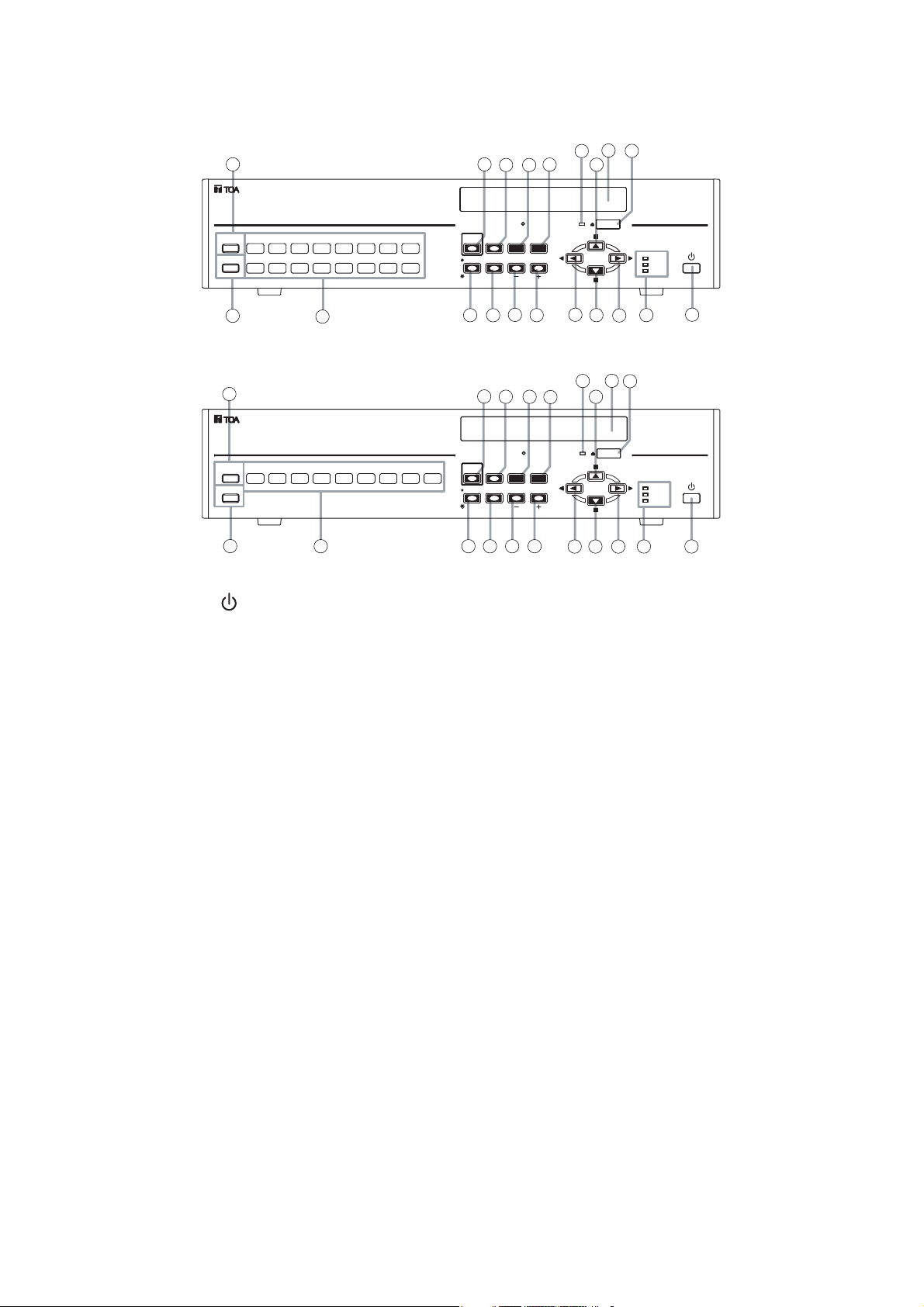
(1) Power key [ ]
Pressing the Power key changes the Digital
Video Recorder's mode from standby to
operation mode. To switch from operation mode
to standby mode, hold down the Power key for 2
seconds or more. (Refer to p. 26; Digital video
recorder activation and termination.)
(2) Archive Terminal
Use this terminal when copying video data
recorded on a hard disk to a USB memory.
(Refer to p. 51; Archive.)
(3) Key lock terminal
Insert the preprogrammed USB key into this
terminal to cancel the security lock setting.
(Refer to p. 60; Securing the digital video
recorder's operating keys.)
(4) Camera selector key
Selects cameras displayed on the live or
playback screens. Pressing the Camera selector
key displays the corresponding camera image
on the full screen.
(5) Priority recording key
Used to start priority recording. To stop priority
recording, hold down the Priority recording key
for 2 seconds or more. The Priority recording
key flashes red during priority recording. (Refer
to p. 39; Priority recording.)
(6) Monitor key
Use this key when switching operation between
Monitor 1 and Monitor 2 outputs.
This key lights when pressed, and extinguishes
when pressed again. Monitor 1 output is
enabled when the key is unlit, and Monitor 2
output is enabled when the key is lit. Monitor 2
output can be operated with the Camera
selector keys, Multi-screen key, and Sequence
key. (Refer to p. 31; Monitor display.)
(7) Buzzer stop key (Alarm reset key)
When priority recording, equipment failure, or
alarm event recording takes place, a buzzer
sounds. Pressing this key disables the buzzer.
Use this key to reset alarm event recording.
Hold down this key for 2 seconds or more to
reset alarm event recording.
(8) Zoom key
Use the Zoom key to zoom in on the live and
playback screens (2x zoom). If this key is
pressed during full-screen display, the cursor for
determining the zoom position is displayed. If
the zoom position is confirmed and the Menu
key is pressed, the 2X zoomed screen is
displayed. Pressing this key again cancels the
zoom mode. (Refer to p. 35; Zoom display.)
7. NOMENCLATURE AND FUNCTIONS
[ C-DR161D Front ]
[ C-DR091D Front ]
KEY LOCK
KEY LOCK
20
19
12
18
11
14
DVD
MENU/
ENTER
REC
FAILUR E
HD FULL
DIGITAL VIDEO RECORDER
REC
FAILURE
HD FULL
1
1
13
15
18
14
11
DVD
MENU/
ENTER
13
15
19
16
20
16
17
DIGITAL VIDEO RECORDER
17
2
1ARCHIVE
1681571461351241131029
3
4
2
9
87654321ARCHIVE
3
4
5
7
BUZZER STOP/
PRIORITY
ALARM RESET
REC
SEARCH
MONITOR 1 SEQUENCESCREEN
MONITOR 2
PRIORITY
MONITOR 1 SEQUENCESCREEN
MONITOR 2
6
MULTI
ZOOM
8
6
10
5
7
BUZZER STOP/
ALARM RESET
REC
SEARCH
MULTI
ZOOM
8
10
9
9
12
Page 15

15
(9) Search key
Use this key to search for recorded images. If
the Search key is pressed when the live or
playback screen is displayed, the search screen
is displayed. To exit the search screen, press
the [ ] key. (Refer to p. 48; Search.)
(10) Multi-Screen / [-] Key
• Multi-screen display
Displays live or recorded camera images on
the multi-segment split screen. The screen
switches to 4-segment, 9-segment and 16segment split screen displays with each
depression of this key. (Refer to p. 34; Multi-
segment split-screen display.)
• Reverse setting value selection [-]
Pressing this key while setting values are
selected on the menu screen varies setting
values in the reverse direction.
• Triplex setting screen activation
If the Multi-Screen key is continuously pressed
for 2 seconds or more while the multi-segment
split screen is displayed, the Triplex setting
screen is displayed. To exit the Setting screen,
hold down the Menu key for 2 seconds or
more. (Refer to p. 36; Triplex display.)
• Position setting screen activation
If the Multi-screen key is continuously pressed
for 2 seconds or more while multi-split screen is
displayed in the Live mode, the Position setting
screen is displayed. To exit the Setting screen,
hold down the Menu key for 2 seconds or
more. (Refer to p. 37; Position setting display.)
(11) Menu key
• Activating the Menu screen
Holding down the Menu key for 2 seconds or
more when the Monitor key remains unlit
displays the menu screen on the Monitor 1
screen. To return to live mode, press the [
] key. (Refer to p. 74; Main menu setting.)
• Menu item confirmation
Use this key when confirming selected setting
items on the menu screen, such as "Yes," "No"
or "Execute." (Refer to p. 74; Main menu
setting.)
• Advancing to the next menu setting screen
Press this key when advancing from the
position indicated by the mark on the
menu setting screen to the next menu setting
screen. (Refer to p. 74; Main menu setting.)
• Exiting the motion setting screen
Hold down the Menu key for 2 seconds or
more to exit the motion detection setting on the
menu screen. (Refer to p. 84; Motion detection
settings.)
• Activating the Password entry screen
Holding down the Menu key for 2 seconds or
more when the Security setting is activated
displays the Password entry screen. (Refer to
p. 96; Security setting.)
(12) Sequence/ [ +] Key
• Sequence
Pressing the Sequence key in live mode
causes the camera outputs to be displayed in
preprogrammed sequential order. (Refer to
p. 35; Sequence display.)
• Forwarding [+] the setting value
Pressing the setting value on the Menu screen
during selection changes the setting value in
forward direction.
(13) Reverse playback [ ] key
• Reverse playback
Images are played back in reverse if the
Reverse playback key is pressed. (Refer to
p. 45; Playback.)
• Moving the cursor to the left on the menu
screen
Use this key to move the cursor to the left on
the menu screen.
• Returning the Menu screen to the previous
screen
Pressing the [ ] key when the cursor
positions to the left on the Menu screen returns
the display to the previous screen.
• Returning to the live mode
Pressing the [ ] key on the Menu screen
returns the display to the live mode.
(14) Pause [ , ] key
• Pause of playback/reverse playback screens
Use this key to temporarily stop the playback
display. Operation can be performed for the
archive menu display, frame advance/reverse
playback, and instant event access playback
while the display is temporarily stopped. (Refer
to p. 51; Archive.) (Refer to p. 45; Playback.)
• Moving the cursor upward on the Menu
screen
Used this key to move the cursor upward on
the Menu screen.
(15) Stop [ , ] key
• Stop of playback/reverse playback
Use this key to stop playback or reverse
playback. (Refer to p. 45; Playback.)
Note
Recording does not stop even if the Stop key
is pressed.
Page 16

16
• Moving the cursor downward on the Menu
screen
Use this key to move the cursor downward on
the Menu screen.
(16) Playback [ ] key
Pressing the Playback key plays back recorded
images. (Refer to p. 45; Playback.)
• Moving the cursor to the right on the Menu
screen
Use this key to move the cursor to the right on
the Menu screen.
(17) Informational Indicator
• Recording indicator
Lights during recording (Priority recording,
Normal recording, Alarm Event recording)
• Failure indicator
Flashes when video is lost or when a fan or
hard disk failure occurs. Refer to the failure log
on the menu screen for the cause of each
equipment failure. The LED flashes until the
Recorder returns to normal state.
• Available hard disk space indicator
Flashes when the available disk space falls
below the specified warning level while in write
protect mode and when the available disk
spaces runs out of time. This indicator does
not light (flash) while in overwrite mode.
(Refer to p. 93; System setting.)
(18) DVD indicator
Flashes when the DVD-R is inserted and while
the inserted disk is being recognized, and
continuously lights while the disk is being
written.
(19) DVD receptacle
Place a DVD-R here when copying data
recorded on the Digital Video Recorder.
(20) DVD eject Key
Use this key to insert or eject a DVD-R.
Page 17
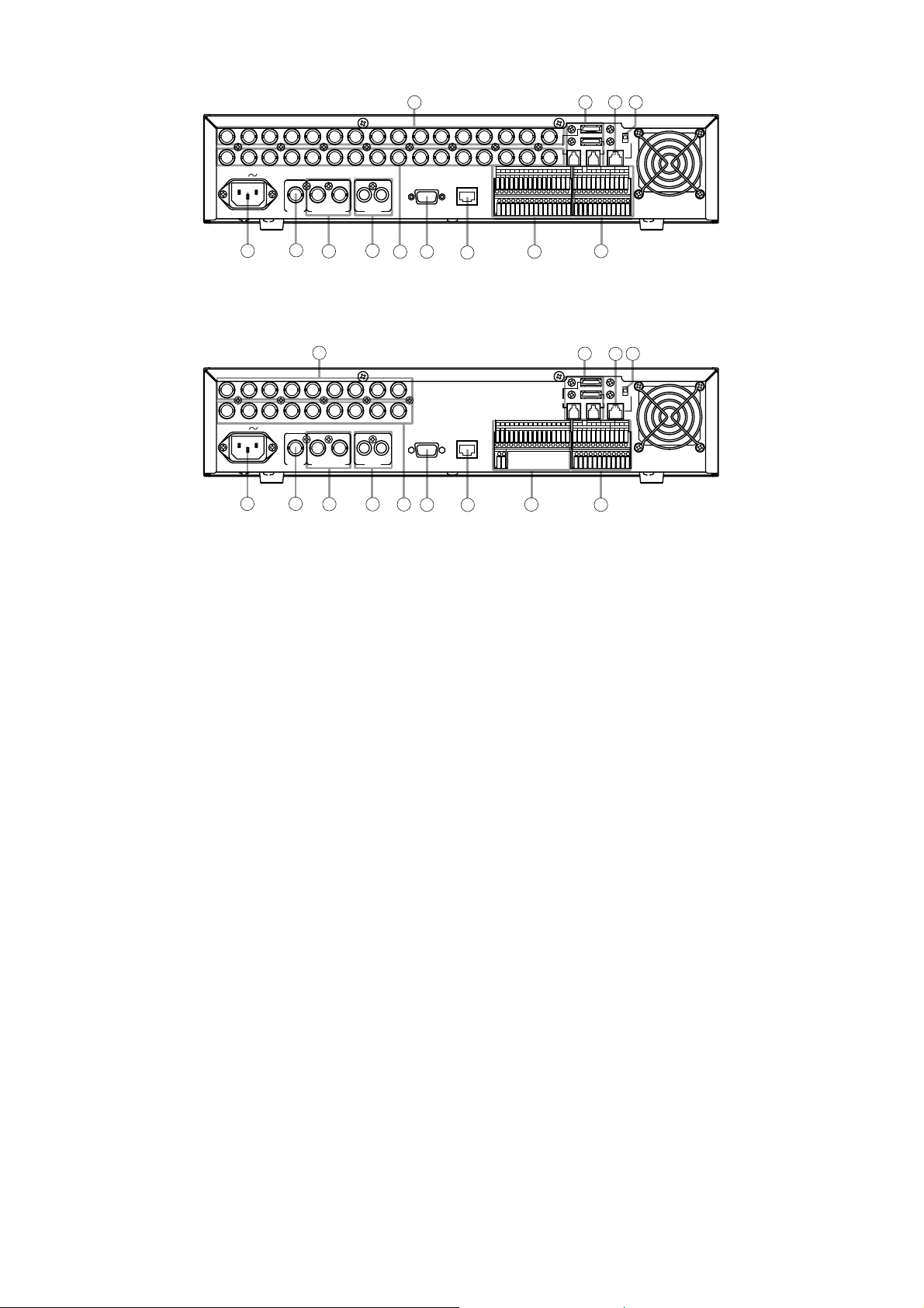
17
[C-DR091D Rear]
[C-DR161D Rear]
(21) AC inlet
Connect the supplied power cord to this socket.
(22) Link input terminal
Use this terminal to cascade-connect two or
more Digital Video Recorders. (Refer to p. 21;
Digital video recorder's expansion system.)
(23) Monitor output terminal
• Monitor 1 output terminal
Outputs the Monitor 1's camera images.
• Monitor 2 output terminal
Outputs Monitor 2’s camera images. Live
images can be displayed in full-screen or 4segment split-screen display. Reproduced
images cannot be output.
(24) Audio input/output terminal
• Audio input terminal
This terminal is used for audio recording.
• Audio output terminal
Outputs audio input terminal signals during live
screen display, and outputs the recorded audio
during playback display.
(25) Video input terminal
Connect the camera to this terminal. Connecting
the camera automatically terminates the Digital
Video Recorder at 75 Ω.
(26) Video output terminal
A loop through output for the Video input terminal.
Connecting the BNC plug to the Video output
terminal automatically cancels the 75Ω
termination.
(27) RS-232C terminal
Connect this terminal to a computer’s RS-232C
terminal when performing control from a
personal computer. Connect this terminal to the
PC's RS-232C terminal using a nullmodem
cable. (Refer to p. 23; RS-232C Terminal
communications specifications.)
(28) LAN terminal
Use this terminal to remotely monitor or control
cameras connected to the Digital Video
Recorder, or search or play back their recorded
images on a PC web browser.
(29) Alarm input terminal
Use this terminal to make Alarm event recording. Connect no-voltage contact signals of
sensors, etc. to this terminal.
(Refer to p. 24; Alarm input terminal connections.) (Refer to p. 94; I/O Terminal mode
setting.)
1
AC MAINS
VIDEO
25
31
33
IN
1615141312111098765432
1
DISK ARRAY
OUT
ALARM IN
1
1681571461351241131029
GGGGGGGG
GGGGGGGG
PRIORITY RM IN-BCAMERA
NC
IN
32
RM
TERMINATION
ON
OFF
RM IN-A
2
RM OUT-B
---+++GGGG
TIME SYNCCONTROL OUT
OUTIN GG
GGGG4321
IN OUT21
23
21
LINK AUDIOMONITOR OUT RS-232C LAN
22
25
1
AC MAINS
21
VIDEO
LINK AUDIOMONITOR OUT RS-232C LAN
22
IN OUT21
23
24
24
26
26
27
28
IN
98765432
OUT
27
28
29
ALARM IN
G
29
30
33
12
DISK ARRAY
PRIORITY RM IN-BCAMERA
GGGGGGGG876543291
IN
32
31
RM
TERMINATION
ON
OFF
RM IN-A
RM OUT-B
NC
---+++GGGG
TIME SYNCCONTROL OUT
OUTIN GG
GGGG4321
30
Page 18

18
(30) Control input/output terminal
• Control output terminal
Outputs a signal during priority recording,
alarm recording or motion detected recording
or when video is lost, the hard disk is full or
equipment failure occurs. (Refer to p. 95;
Control output terminal setting.)
• Priority recording input terminal
Use this terminal to begin Priority recording
using signals from connected external
equipment. Connect no-voltage contact signals
of switches, etc. to this terminal.
• Time sync input & output terminal
Use this terminal to synchronize the clocks of
multiple Digital Video Recorders used in the
system. Connect the master Recorder's Time
sync output to the slave Recorder's Time sync
input. Time sync settings must be performed
on the menu screen. (Refer to p. 23; External
terminal connections.)
• Remote Control Input/Output Terminal B
Use this terminal for connection of the CRM1000 Remote Controller. Note the correct
polarity (positive and negative orientation). Use
the Remote control input & output terminal B if
the cable distance is longer than 3 meters (9.8
ft). (Refer to p. 20; Connections)
Also use this terminal to cascade-connect the
Digital Video Recorder. Connect the first
Digital Video Recorder's Remote control output
terminal to the second Recorder's Remote
control input terminal. Note the correct polarity.
(Refer to p. 21; Digital video recorder's
expansion system.)
• Camera control terminal
Use this terminal to control the Combination
Camera. Connect this terminal to the camera's
control terminal (RS-485). Note the correct
polarity. (Refer to p. 20; Connections)
Note
The C-RM1000 Remote Controller must be
connected to the Digital Video Recorder in
order to control the Combination Camera.
(31) Remote controller input terminal A ( Power
can be supplied.)
Use this terminal to connect the C-RM1000
Remote Controller. Use the supplied cable for
connection if the distance to the controller is
shorter than 3 meters (9.8 ft). Power is supplied
to the Remote Controller from the Digital Video
Recorder if this terminal is used.
(32) Termination switch
Terminal switch for Remote Control input &
output terminals A and B.
The ON position terminates the connection at
220Ω. The 220Ω termination is not available
when this switch is set to the OFF position.
(33) Disk array connection terminal
This terminal is used for Disk Array connection.
Up to 2 Disk Arrays can be connected to this
terminal.
Page 19
19
Notes
• The rack mounting screws supplied with the MB-23B can be used for the TOA equipment rack only. Do not
use them for other racks.
• Use the Digital Video Recorder in locations with ambient temperature of between +5°C and +40°C (41°F and
104°F). When rack-mounting the Digital Video Recorder, the ambient temperature must be kept 35°C (95°F)
or below.
• The Recorder is equipped with an internal cooling fan. Never block the fan exhaust vent.
• Avoid installing the Digital Video Recorder in locations exposed to vibration.
a) Elevated Operating Ambient Temperature - If installed in a closed or multi-unit rack assembly, the operating
ambient temperature of the rack environment may be greater than room ambient. Therefore, consideration
should be given to installing the equipment in an environment compatible with the manufacturer's maximum
rated ambient temperature (Tmra).
b) Reduced Air Flow - Installation of the equipment in a rack should be such that the amount of air flow
required for safe operation of the equipment is not compromised.
c) Mechanical Loading - Mounting of the equipment in the rack should be such that a hazardous condition is
not achieved due to uneven mechanical loading.
d) Circuit Overloading - Consideration should be given to the connection of the equipment to the supply circuit
and the effect that overloading of circuits might have on overcurrent protection and supply wiring.
Appropriate consideration of equipment nameplate ratings should be used when addressing this concern.
e) Reliable Earthing - Reliable earthing of rack-mounted equipment should be maintained. Particular attention
should be given to supply connections other than direct connections to the branch circuit (e.g., use of power
strips).
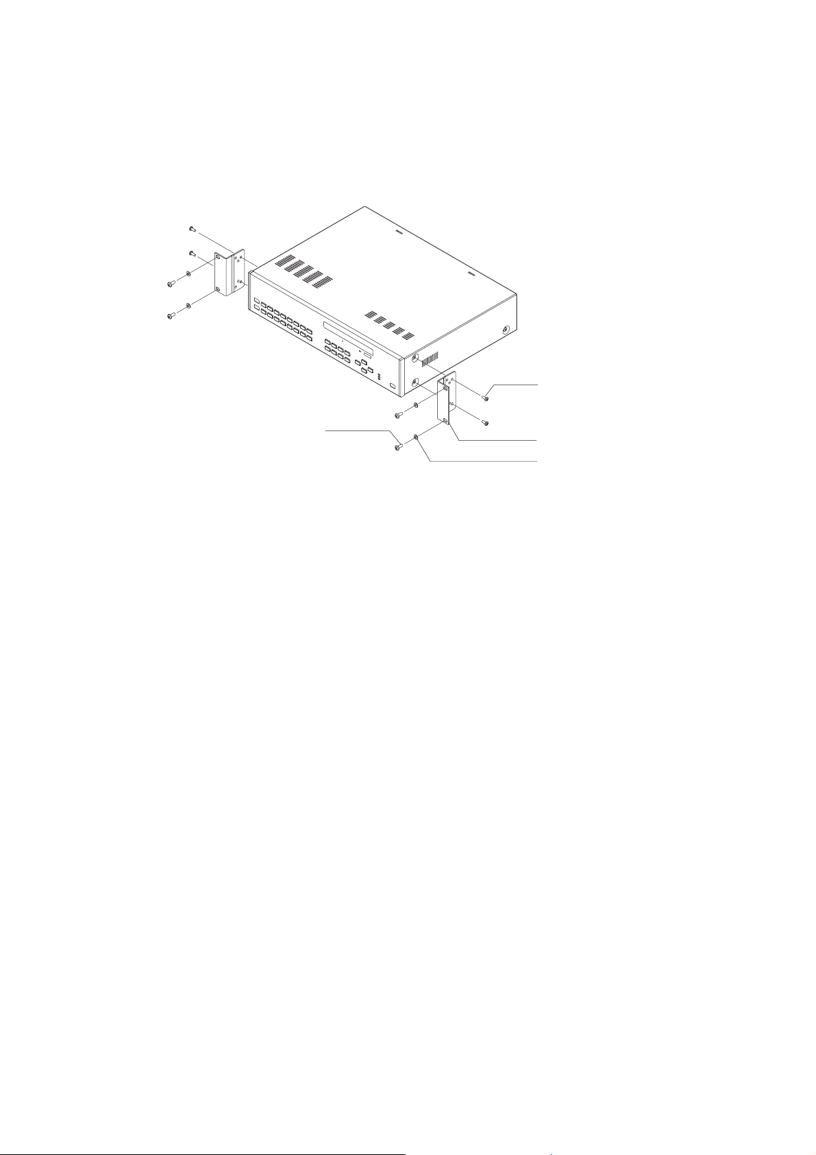
8. RACK MOUNTING
Use the optional MB-23B Rack Mounting Bracket when mounting the Digital Video Recorder in an equipment
rack. Remove 4 rubber feet on the bottom surface by loosening their respective fixing screws with a standard
screwdriver.
C-DR091D
C-DR161D
M4 x 12 binding head screw
(supplied with the MB-23B)
Rack mounting screw 5 x 12
(supplied with the MB-23B)
MB-23B (optional)
M5 fiber washer
(supplied with the MB-23B)
Page 20
20
9. CONNECTIONS
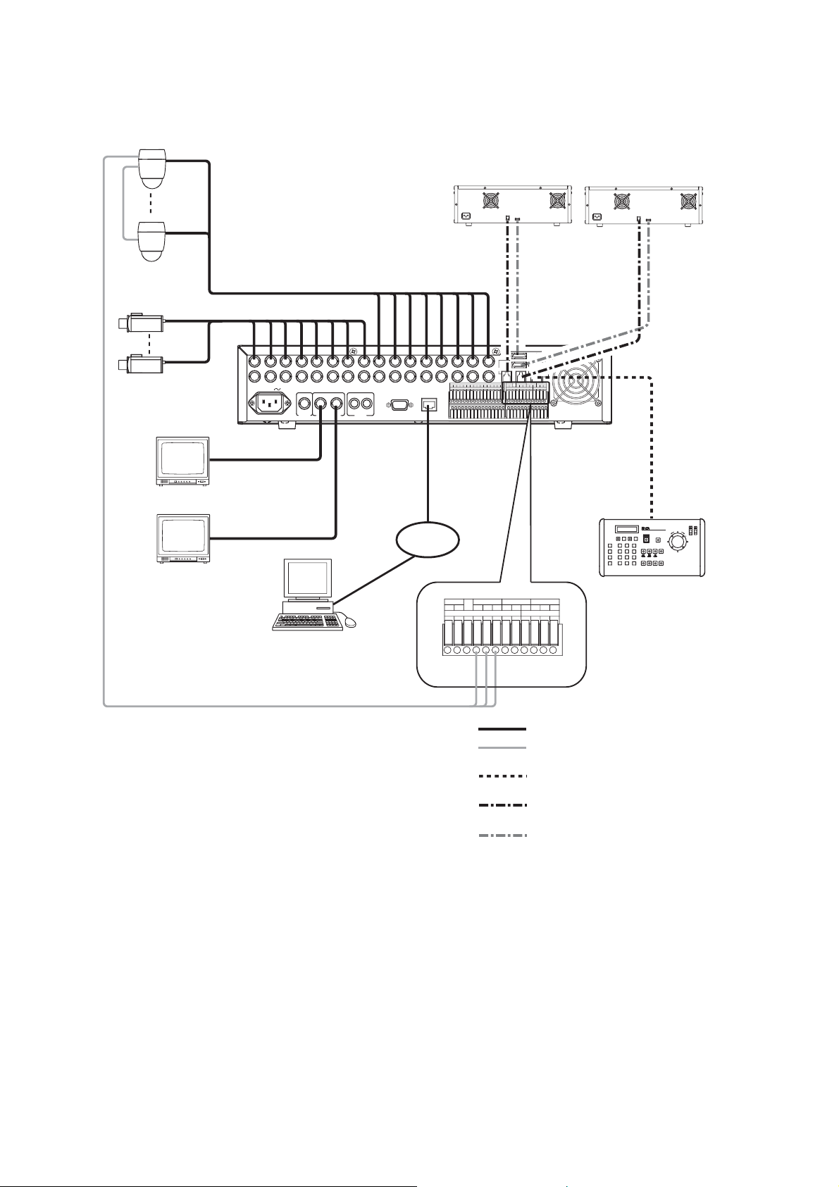
9.1. Basic System
9.2. About Star Wiring
A C-IF500 Interface Unit is required when using star wiring for a Combination Camera’s control lines (RS-
485). Refer to the Interface Unit’s instruction manual for specific details on control line connections.
Combination camera
RS-485
Color camera
2
*
2
*
Digital Video Recorder
*
C-DR161D
Disk Array Disk Array
DISK
ARRAY
RM
TERMINATION
IN
1
1
AC MAINS
LINK AUDIOMONITOR OUT RS-232C LAN
MONITOR
OUT1
VIDEO
IN OUT21
MONITOR
OUT2
LAN
1615141312111098765432
1
OUT
ALARM IN
1
GGGGGGGG
GGGGGGGG
1681571461351241131029
DISK ARRAY
PRIORITY RM IN-BCAMERA
IN
ON
OFF
RM IN-A
2
RM OUT-B
NC
---+++GGGG
TIME SYNCCONTROL OUT
OUTIN GG
GGGG4321
RM IN-A
Monitor 1
Live only
Monitor 2
1
C-DR091D: 9 I/ O Terminals
*
C-DR161D: 16 I/ O Terminals
2
Match the Combination Camera’ s address to the Digital Video
*
Recorder’ s video input number.
PC
RS-485
LAN
---
RM OUT-B
GGIN OUT
CAMERA RM IN-BPRIORITY
NC
IN
GGGG
+++
CONTROL OUT TIME SYNC
1234GGGG
CAMERA
+
-
G
: Coaxial cable (Video signal)
: CPEV-S 0.65 (RS-485 Control line)
Twisted pair with shield 22AWG or larger
: Modular cable, 3 m (9.8 ft).
(supplied with the C-RM1000)
: Modular cable, 1 m (3.3 ft)
(supplied with Disk Array)
: eSATA cable, 1 m (3.3 ft)
(supplied with Disk Array)
DVR CONTROL
OUTPUT-A
Remote Controller
C-RM1000
Page 21
21
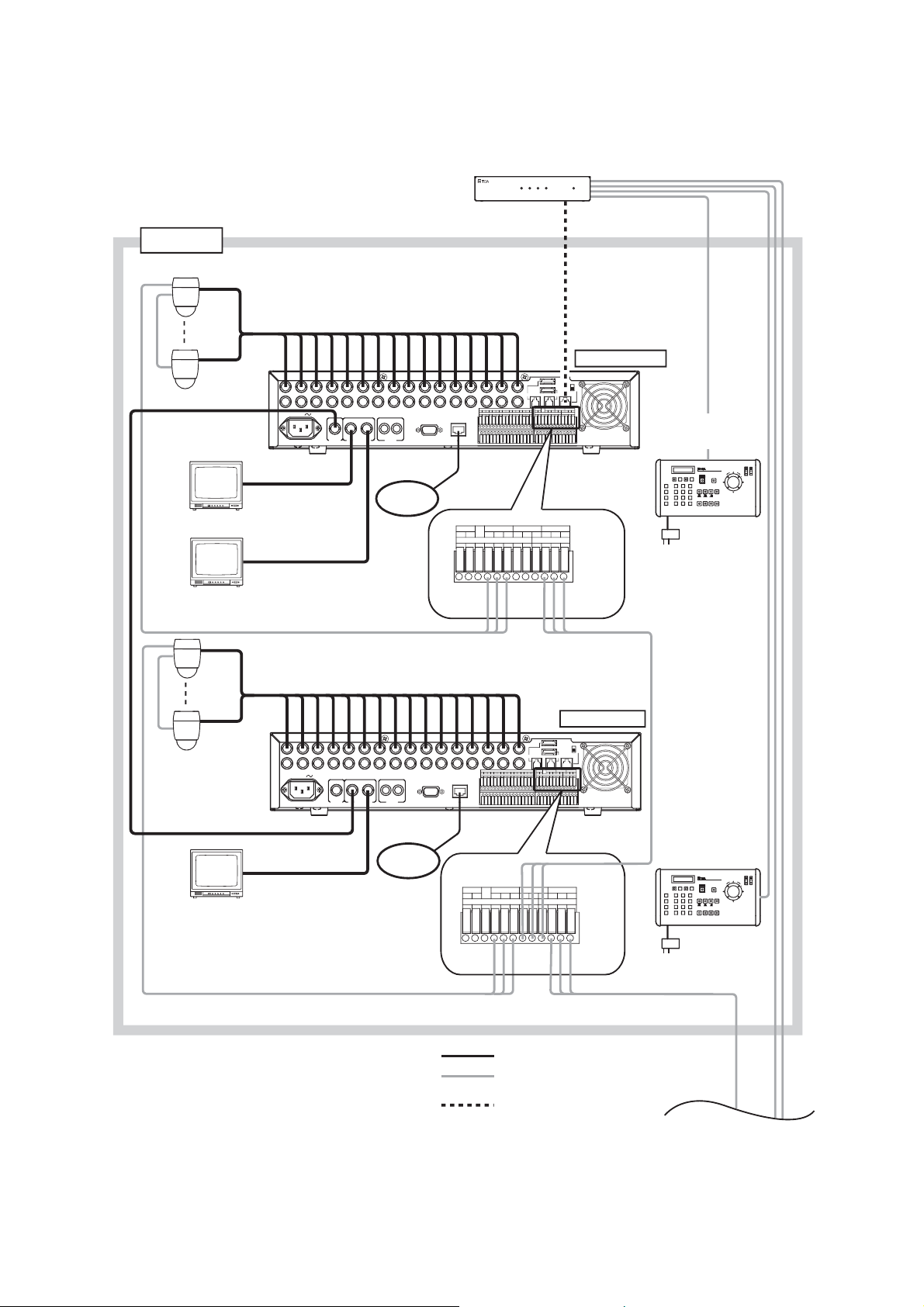
9.3. Digital Video Recorder’s Expansion System (Cascade connection)
Notes
• A cascade-connected system generally requires the Remote Controller(s).
• It is necessary to set DVR-ID in the cascade-connected system. (Refer to p. 27; Setting the DVR-ID.)
REMOTE CONTROLLER
DVR CONTROL
OUTPUT-A
POWER/DVR4321
INTERFACE UNIT C-RF1000
CONTROLLER
REMOTE
INPUT-B
Group 1
Combination camera
RS-485
Interface unit
C-RF1000
LINK
Group 1
Master
Monitor
*
Digital Video Recorder 1
C-DR161D
Monitor 1
Live only
Monitor 2
Digital Video Recorder 2
C-DR161D
Live only
*
Monitor 2
1
1
1
AC MAINS
LINK AUDIOMONITOR OUT RS-232C LAN
MONITOR
OUT 1
MONITOR
OUT 2
RS-485
1
AC MAINS
LINK AUDIOMONITOR OUT RS-232C LAN
MONITOR
OUT 1
MONITOR
OUT 2
IN OUT21
To LAN
IN OUT21
To LAN
DISK ARRAY
PRIORITY RM IN-BCAMERA
IN
NC
Termination: OFF
RM
TERMINATION
ON
OFF
RM IN-A
2
RM OUT-B
---+++GGGG
TIME SYNCCONTROL OUT
OUTIN GG
GGGG4321
2
*
Remote Controller 1
C-RM1000
RM IN-A
IN
1615141312111098765432
1
OUT
ALARM IN
VIDEO
1
GGGGGGGG
GGGGGGGG
1681571461351241131029
LAN
CAMERA RM IN-BPRIORITY
NC
IN
+++
GGGG
CONTROL OUT TIME SYNC
1234GGGG
CAMERA
+
-
G
VIDEO
1
---
IN
1615141312111098765432
1
OUT
ALARM IN
GGGGGGGG
GGGGGGGG
1681571461351241131029
RM OUT-B
GGIN OUT
RM
OUT-B
Termination: OFF
RM
TERMINATION
RM IN-A
2
DISK ARRAY
PRIORITY RM IN-BCAMERA
RM OUT-B
NC
IN
TIME SYNCCONTROL OUT
OUTIN GG
GGGG4321
AC adaptor
RS-485
ON
OFF
---+++GGGG
2
*
LAN
Remote Controller 2
C-RM1000
RM IN-B
CAMERA RM IN-BPRIORITY
NC
+++
GGGG
IN
CONTROL OUT TIME SYNC
1234GGGG
---
RM OUT-B
GGIN OUT
RS-485
1
C-DR091D: 9 I/ O Terminals
*
C-DR161D: 16 I/ O Terminals
2
For the maximum cable length between the C-RF1000
*
Interface Unit and the C-RM1000 Remote Controller,
refer to C-RM1000 operation manual.
CAMERA
-
+
G
RM
OUT-B
AC adaptor
RS-485
: Coaxial cable (Video signal)
: CPEV-S 0.65 (RS-485 Control line)
Twisted pair with shield 22AWG or larger
: Modular cable, 3 m (9.8 ft)
(supplied with the C-RF1000)
To next page
Page 22
22
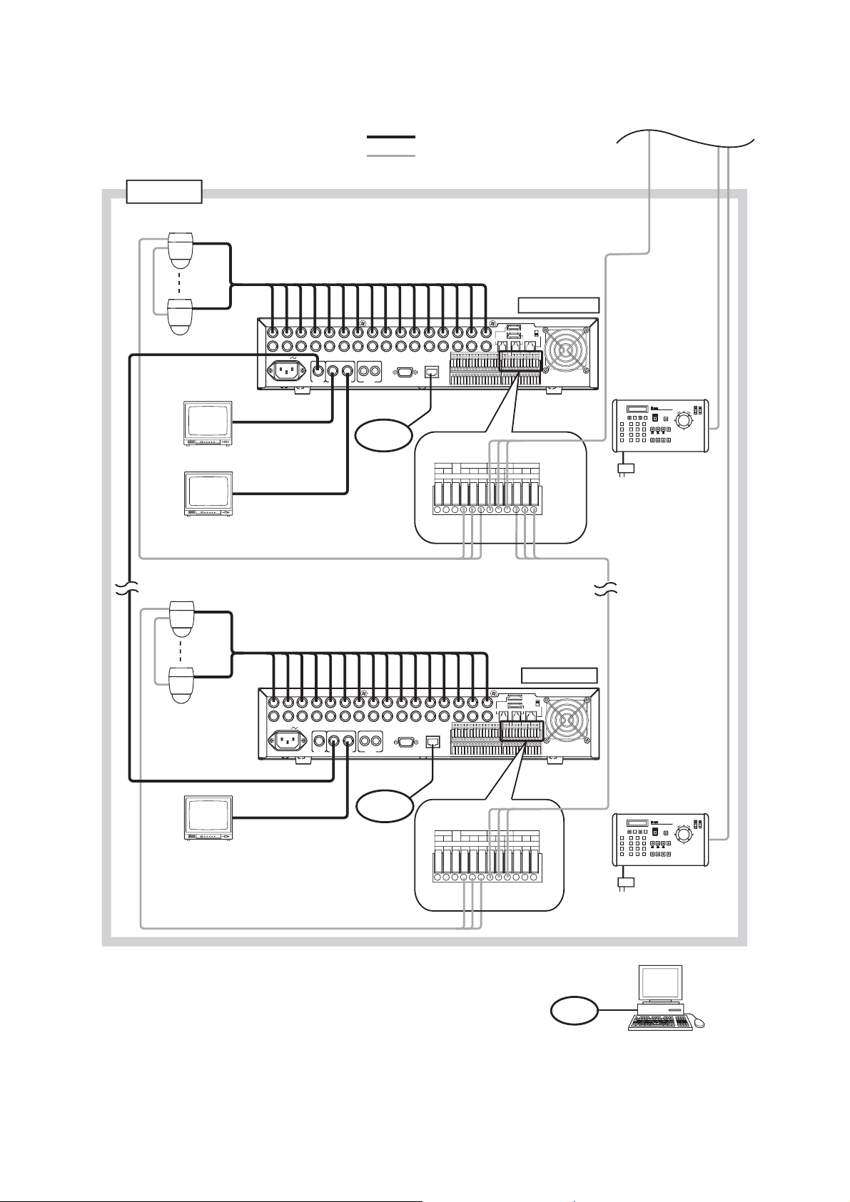
Group 2
From previous page
: Coaxial cable (Video signal)
: CPEV-S 0.65 (RS-485 Control line)
Twisted pair with shield 22AWG or larger
RS-485
Combination camera
Digital Video Recorder 3
C-DR161D
Monitor 1
Monitor 2
Combination camera
Group 2
Master
Monitor
Live only
LINK
Termination: OFF
RM
TERMINATION
IN
1
AC MAINS
1
*
LINK AUDIOMONITOR OUT RS-232C LAN
MONITOR
OUT 1
MONITOR
OUT 2
VIDEO
IN OUT21
To LAN
LAN
IN
1234GGGG
CAMERA
+
G
1615141312111098765432
1
OUT
ALARM IN
1
1681571461351241131029
RM IN-B
CAMERA RM IN-BPRIORITY
NC
GGGG
+++
---
CONTROL OUT TIME SYNC
-
GGGGGGGG
GGGGGGGG
DISK ARRAY
PRIORITY RM IN-BCAMERA
NC
IN
RM OUT-B
GGIN OUT
ON
OFF
RM IN-A
2
RM OUT-B
---+++GGGG
TIME SYNCCONTROL OUT
OUTIN GG
GGGG4321
Remote Controller 3
C-RM1000
2
*
AC adaptor
RM
OUT-B
RS-485
1
Digital Video Recorder 8
C-DR161D
*
Live only
AC MAINS
1
LINK AUDIOMONITOR OUT RS-232C LAN
MONITOR
OUT 1
MONITOR
OUT 2
VIDEO
IN OUT21
To LAN
Monitor 2
RS-485
1
C-DR091D: 9 I/ O Terminals
*
C-DR161D: 16 I/ O Terminals
2
For the maximum cable length between the C-RF1000 Interface Unit and
*
the C-RM1000 Remote Controller, refer to C-RM1000 operation manual.
Termination: ON
RM
TERMINATION
IN
1615141312111098765432
1
OUT
ALARM IN
1
1681571461351241131029
GGGGGGGG
GGGGGGGG
DISK ARRAY
PRIORITY RM IN-BCAMERA
IN
ON
OFF
RM IN-A
2
RM OUT-B
NC
---+++GGGG
TIME SYNCCONTROL OUT
OUTIN GG
GGGG4321
LAN
RM IN-B
CAMERA RM IN-BPRIORITY
NC
+++
GGGG
IN
CONTROL OUT TIME SYNC
1234GGGG
CAMERA
+
-
G
---
RM OUT-B
GGIN OUT
LAN
RS-485
Remote Controller 4
C-RM1000
AC adaptor
PC
2
*
Page 23

23
Note
RS-232C connector plug is not supplied with the Digital Video Recorder.
For RS-232C connection to PC, use null modem cable.
10. EXTERNAL TERMINAL CONNECTIONS
10.1. RS-232C Terminal Communications Specifications
The Digital Video Recorder can be controlled by a PC or other equipment via a connection through the RS232C port. However:
Notes
• Control software is not available as standard accessory.
• TOA takes no responsibility for hardware or software failures or damages resulting from the use of third-
party control software.
10.1.1. Communications protocol
Transfer System: Start/stop system
Parity Bit: Even number
Transfer Speed: 9,600 bps, 19,200 bps, and 38,400 bps
Code: Binary code
Bit Length: 8 bits
Flow Control: CTS/RTS handshake or none
Stop Bit: 1
Error Control: None
10.1.2. RS-232C Connector pin arrangement
The following signal names are assigned to each pin of the RS-232C D-sub 9P male connector:
10.2. LAN Terminal Connection
Use this terminal to remotely monitor or control cameras connected to the Digital Video Recorder, or search or
play back their recorded images on a PC web browser. When connecting a PC directly to the Digital Video
Recorder, use a network crossover cable. Use the straight-through cable for connection between them via a
switching hub.
Terminal No.
1
2
3
4
5
6
7
8
9
Symbol
NC
RD
SD
NC
SG
NC
RS
CS
NC
Name
Not connected
Receiving data
Sending data
Not connected
Signal ground
Not connected
Request to send
Clear to send
Not connected
1
6
5
9
Page 24
24
For 16 channel For 9 channel
Applicable cable
• Solid conductor
AWG26 (ø 0.4 mm)
-
AWG16 (ø 1.2 mm)
• Stranded conductor
AWG24 (0.2 mm
2
)
-
AWG20 (0.75 mm2)
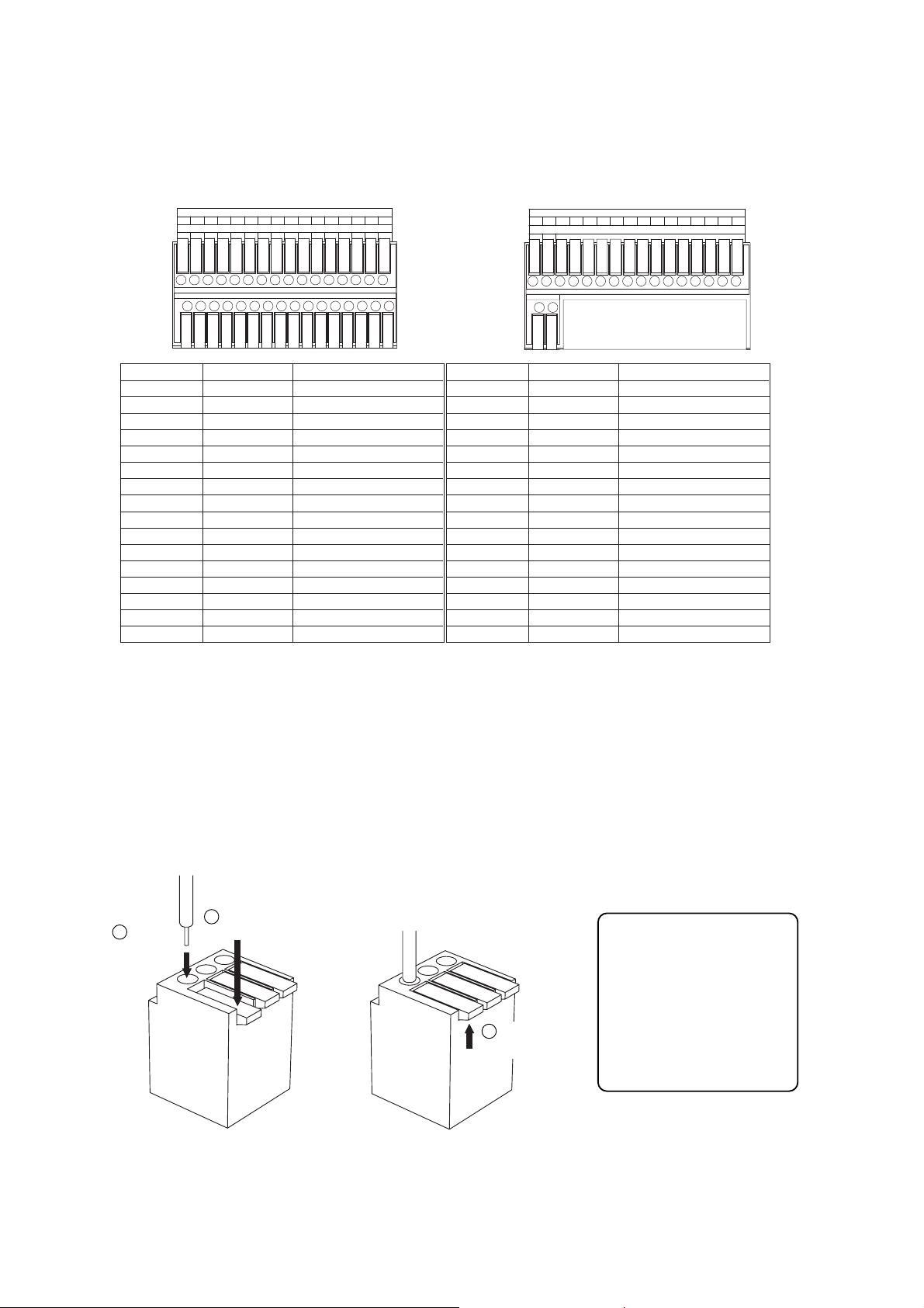
10.3. Alarm Input Terminal Connections
The number of terminals available differs depending on whether the Digital Video Recorder is a 9-channel or a
16-channel version. Refer to the table below when making alarm input terminal connections.(Refer to p. 14;
Nomenclature and functions)
10.3.1. Terminal connection
The terminal connector is unlocked by pressing down on its release button. To connect the cable, press down
on the release button first, insert the cable, then push the release button up again to lock the cable in place.
However, for solid cables with diameters from 0.8 mm(AWG20) to 1.2 mm(AWG16), there is no need to press
down on the release button. Cable can be connected simply by inserting it in place until it will not go any
further.
Note
Ensure that the cable is securely locked into the terminal after connection.
1
9
Terminal name
1
G
2
G
3
G
4
G
5
G
6
G
7
G
8
G
3102
11
Symbol
ALARM 1
GND
ALARM 2
GND
ALARM 3
GND
ALARM 4
GND
ALARM 5
GNA
ALARM 6
GND
ALARM 7
GND
ALARM 8
GND
ALARM IN
13
5124
6
14
16
Name
Alarm input 1
Signal ground
Alarm input 2
Signal ground
Alarm input 3
Signal ground
Alarm input 4
Signal ground
Alarm input 5
Signal ground
Alarm input 6
Signal ground
Alarm input 7
Signal ground
Alarm input 8
Signal ground
GGGGGGGG
8157
GGGGGGGG
Terminal name
9
G
10
G
11
G
12
G
13
G
14
G
15
G
16
G
G
Symbol
ALARM 9
GND
ALARM 10
GND
ALARM 11
GND
ALARM 12
GND
ALARM 13
GNA
ALARM 14
GND
ALARM 15
GND
ALARM 16
GND
ALARM IN
Alarm input 9
Signal ground
Alarm input 10
Signal ground
Alarm input 11
Signal ground
Alarm input 12
Signal ground
Alarm input 13
Signal ground
Alarm input 14
Signal ground
Alarm input 15
Signal ground
Alarm input 16
Signal ground
GGGGGGGG876543291
Name
1
Press down the
2
Insert a cable.
Release button.
3
Push the
release button up.
Page 25
25
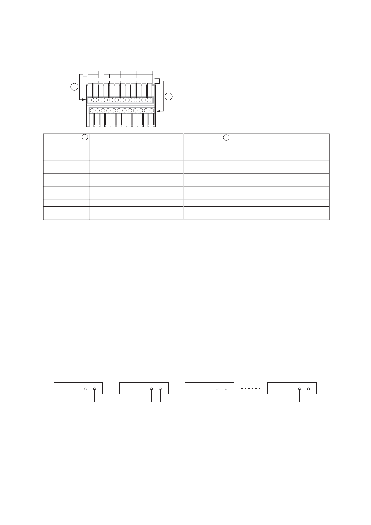
10.4. Control I/O Terminal Connections
The control input and output terminals include: priority recording terminal, camera control terminal, remote
controller input/output terminals, control output terminal, and time synchronization input/output terminals.
(Refer to p. 14; Nomenclature and functions.)
Notes
• Ensure that the cable is securely locked into the terminal after connection. (Refer to p. 24; Alarm input
terminal connections.)
• Use the CPEV-S cable (twisted pair shielded cable) with diameter larger than 0.65 mm for the Control Input
/Output terminal connections. Also be sure to connect the shielded cable to the GND terminal.
• The maximum cable length of the control cable from the Digital Video Recorder to the camera of which
termination is set to ON is 1.2 km. Also the maximum cable length of the control cable from the Remote
Controller to the Digital Video Recorder of which termination switch is set to ON is 1.2 km.
10.4.1. Time synchronization input/output terminal connections
Two different methods are available to synchronize the time, one using both master and slave units, the other
using NTP. (Refer to p. 100; Date/time setting.)
Note
When synchronizing a single-channel Digital Video Recorder, set the synchronization interval to "5 seconds."
(Refer to p. 100; Date/time setting.)
To synchronize the times of slave units with the time of the master unit, connect the slave units to the master
unit in a series via their input and output terminals. In other words, connect the input of slave number 1 to the
master unit’s output and the input of slave number 2 to slave number 1’s output, and so on.
PRIORITY RM IN-BCAMERA
NC
+
IN
RM OUT-B
++
--
-
GGGG
TIME SYNCCONTROL OUT
OUTIN GG
GGGG4321
A
B
Terminal name
PRIORITY IN
PRIORITY G
NC
CAMERA
+
CAMERA G
CAMERA
RM IN-B
-
+
RM IN-B G
RM IN-B
RM OUT-B
RM OUT-B G
RM OUT-B
A
Name
Priority Recording Input
Priority Recording Ground
Not connected
Camera Control (RS-485) +
Camera Control (RS-485) Ground
Camera Control (RS-485)
Remote Control Input B + (RS-485)
Remote Control Input B Ground
Remote Control Input B
+
Remote Control Output B + (RS-485)
Remote Control Output B Ground
-
Remote Control Output B
-
-
(RS-485)
-
(RS-485)
Terminal name
B
CONTROL OUT 1
CONTROL OUT G
CONTROL OUT 2
CONTROL OUT G
CONTROL OUT 3
CONTROL OUT G
CONTROL OUT 4
CONTROL OUT G
TIME SYNC IN
TIME SYNC G
TIME SYNC OUT
TIME SYNC G
Name
Control Output 1
Control Output Ground
Control Output 2
Control Output Ground
Control Output 3
Control Output Ground
Control Output 4
Control Output Ground
Date/Time Adjustment Input
Date/Time Adjustment Input Ground
Date/Time Adjustment Output
Date/Time Adjustment Output Ground
Master
Input Output
Slave 1
Input Output
Slave 2
Input Output
Input Output
Slave 7
Page 26
26
Notes
• When the Recorder is used for the first time, the date and time could not be correctly displayed. Perform the
clock setting before use. (Refer to p. 100; Date/time setting.)
• When the Digital Video Recorder is switched to standby mode, it cannot be switched on for about 20
seconds.
• Priority recording and auto-recording cannot be made in standby mode. Be sure to press the Power key
when making recording.
11.2. Recorder's Power Off and Disconnect
Hold down the Power key for 2 seconds or more. All operations stop, placing the Recorder in standby mode.
When moving the Recorder, be sure to place it in standby mode, then remove the power supply plug from the
wall outlet.
11. DIGITAL VIDEO RECORDER ACTIVATION AND TERMINATION
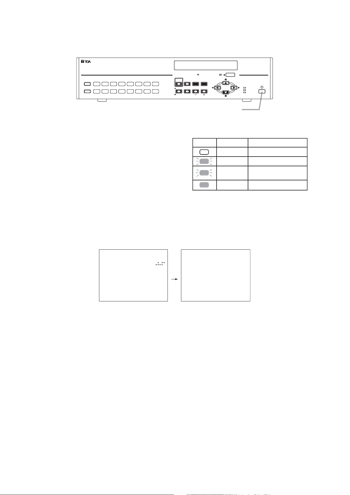
11.1. Recorder's Activation
1. Connect each component correctly. (Refer to p. 20; Connections.)
2. Insert the power supply plug.
The Recorder is placed in standby mode. The power
key flashes at about 5-second intervals while in standby
mode.
Note
Do not pull out the power supply plug while the Power
key is light green. Ensure that the Recorder is in the
standby mode when pulling out the power supply plug.
Logged data could be damaged or lost if the power
supply plug is pulled out during initialization (while
accessing the hard disk).
3. Press the Power key while the Recorder is in standby mode.
The screen automatically changes as shown below. The Power key flashes green during a system check.
The Power key changes from flashing to steady ON after system check completion, allowing camera
images to be displayed.
DVD
MENU/
ENTER
REC
FAILUR E
HD FULL
DIGITAL VIDEO RECORDER
KEY LOCK
BUZZER STOP/
1ARCHIVE
1681571461351241131029
PRIORITY
ALARM RESET
REC
SEARCH
MONITOR 1 SEQUENCESCREEN
MONITOR 2
MULTI
ZOOM
Power key
Power key LED indicator
Distinguishes Main power OFF
Flashes (5sec)
Flashes (1sec)
Lights
Mode
Standby mode
During a system check
(during activation)
Power ON (during operation)
Ver .
SYSTEM CHECK I N PROGRESS.
PLEASE WAIT .
Page 27

27
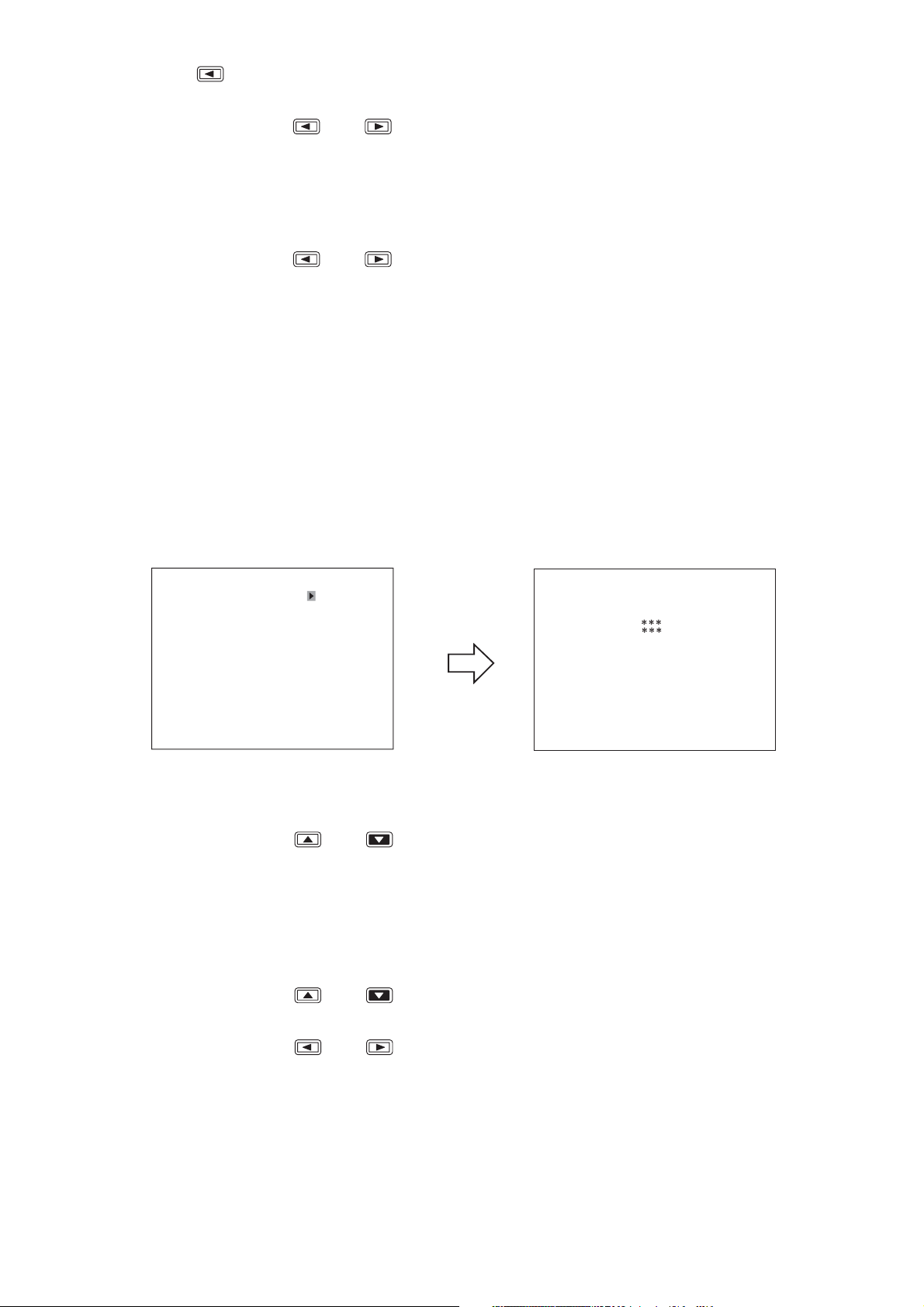
1. Hold down the Menu key for 2 seconds or more.
The main menu screen is displayed.
2. Move the cursor with the [ ] and [ ] keys to select "DATE/TIME SETTING," then press the Menu
key.
The clock setting screen is displayed.
3. Move the cursor with the [ ] and [ ] keys and perform clock settings using the [+] and [-] keys.
Set year, month, date, hour, minute, and second.
12. INITIAL SETTINGS
Be sure to perform the following settings before using the Digital Video Recorder. Failure to do so may lead to
incorrect operation of each function.
• DVR-ID setting (When cascade-connecting)
Note: When cascade-connecting the Digital Video Recorders, set the DVR-ID first. Otherwise, the Menu
screen is not displayed.
• Clock settings
• Hard disk initialization
• Auto-Recording settings
12.2. Clock Settings
Perform clock settings of the Digital Video Recorder. Adjust the date and time in Clock Settings on the menu
screen. (Refer to p. 100; Date/time setting.)
Notes
• If the clock setting is not performed, video recordings are not made according to the schedule set in the
auto-recording setting.
• In some cases, changing the current time may make it impossible to play back the recorded images
correctly when duplicated time data exists in the recording data.
J
A
N
12.1. Setting the DVR-ID
When cascade-connecting the Digital Video Recorders, set different DVR-ID for all individual Digital Video
Recorders. DVR-ID are all factory-preset to "1." Follow the procedure below to set DVR number.
(Refer to p. 21; Digital video recorder's expansion system.)
1. Press the Digital Video Recorder’s Power key while holding down the Sequence key in standby mode.
Camera Selection keys 1 – 8 flashes for about 1minute.
2. Press the desired DVR-ID to set.
The selected number flashes three times, then the number is programmed as DVR-ID.
Note: It is impossible to operate the Digital Video Recorder when the main power is set to OFF. Operate the
Digital Video Recorder after placing it in standby mode.
MA I N MEN U
REC SE TT ING
DISPLAY SETTING
NETWORK SET T I NG
MA I L S E T T I NG
SYSTEM SETT I NG
LOG D ISP LAY
DATE/TIME SETTING
MA I NT ENANCE
I MAGE ARCH I V I NG
Menu key
DATE/TIME SETTING
DATE/TIME SETTING
DATE/TIME ADJUST OPERATE SLAVE
DATE/TIME ADJUST TIME 00:00
DATE/ T I ME ADJUST OUTPUT 1SEC
DAYL IGHT S ET T I NG ON
START DATE / T IME
END DATE /T IME
JAN / 1 /05 00 :00 :00
APR 1ST WEEK SUN 02 : 00
OCT L AS T WEE K SUN 0 2 : 0 0
Page 28
28
1. Hold down the Menu key for 2 seconds or more.
The main menu screen is displayed.
2. Move the cursor with the [ ] and [ ] keys to select "MAINTENANCE," then press the Menu key.
The Equipment Maintenance screen is displayed.
3. Select "HD INITIALIZE," then press the Menu key.
The Hard Disk Initialization screen is displayed.
4. Select the disk mode using the [+] and [-] keys.
Select "NORMAL," or "MIRROR." (Refer to p. 38; Before recording.)
5. Move the cursor with the [ ] and [ ] keys to select "EXECUTE," then press the Menu key.
"Yes" and "Cancel" are displayed.
6. Move the cursor with the [ ] and [ ] keys to select "YES," then press the Menu key.
Confirmation message is displayed after executing the hard disk initialization.
7. Select "OK," then press the Menu key.
The display returns to the hard disk initialization screen.
12.3. Hard Disk Initialization
Set disk mode (normal mode and mirror mode) used for recording to the hard disk to initialize the hard disk.
(Refer to p. 101; Equipment maintenance.)
Notes
• Since initializing the hard disk erases all recorded images, be sure to copy the necessary data to DVD-R
disk or USB memory before initialization.
• Disk mode is factory-preset to "NORMAL." Leave the disk mode as it is when using the Digital Video
Recorder in normal mode. However, it is recommended that the hard disk be initialized since recording
starts automatically when the Digital Video Recorder's power is switched on.
4. Press the [ ] key while the cursor is set to the leftmost selection item on the screen.
The indication will appear to ask whether or not to save the setting.
5. Move the cursor with the [ ] and [ ] keys, select "YES," then press the Menu key.
The message requesting a reboot is displayed.
Note
There is no need to reboot the DVR if not synchronizing using the NTP server, though the message
requesting a reboot is displayed after the clock setting has been saved. (The changed setting is reflected in
the device without rebooting the DVR.)
6. Move the cursor with the [ ] and [ ] keys to select "NO," then press the Menu key.
The display reverts to the main menu screen.
MA I NT ENANCE
HD I NI T I AL I ZE
SETT I NG I N I T I AL I ZE EXECUTE
LOG I N I T IAL I Z E EXECUTE
EXPORT SETT I NG DATA EXECUTE
IMPORT SETT ING DATA EXECUTE
USB KEY REG I STRAT ION EXECUTE
USB KEY DATA ERASURE EXECUTE
D I SK ARRAY 1 UNU SED
D I SK ARRAY 2 UNU SED
Menu key
HD INIT IALIZE
DISK MODE NORMAL
EXECUTE EXECUTE
HDD– A MAS TER GB S LAV E
HDD–B MASTER GB SLAVE DVD
-----
Page 29
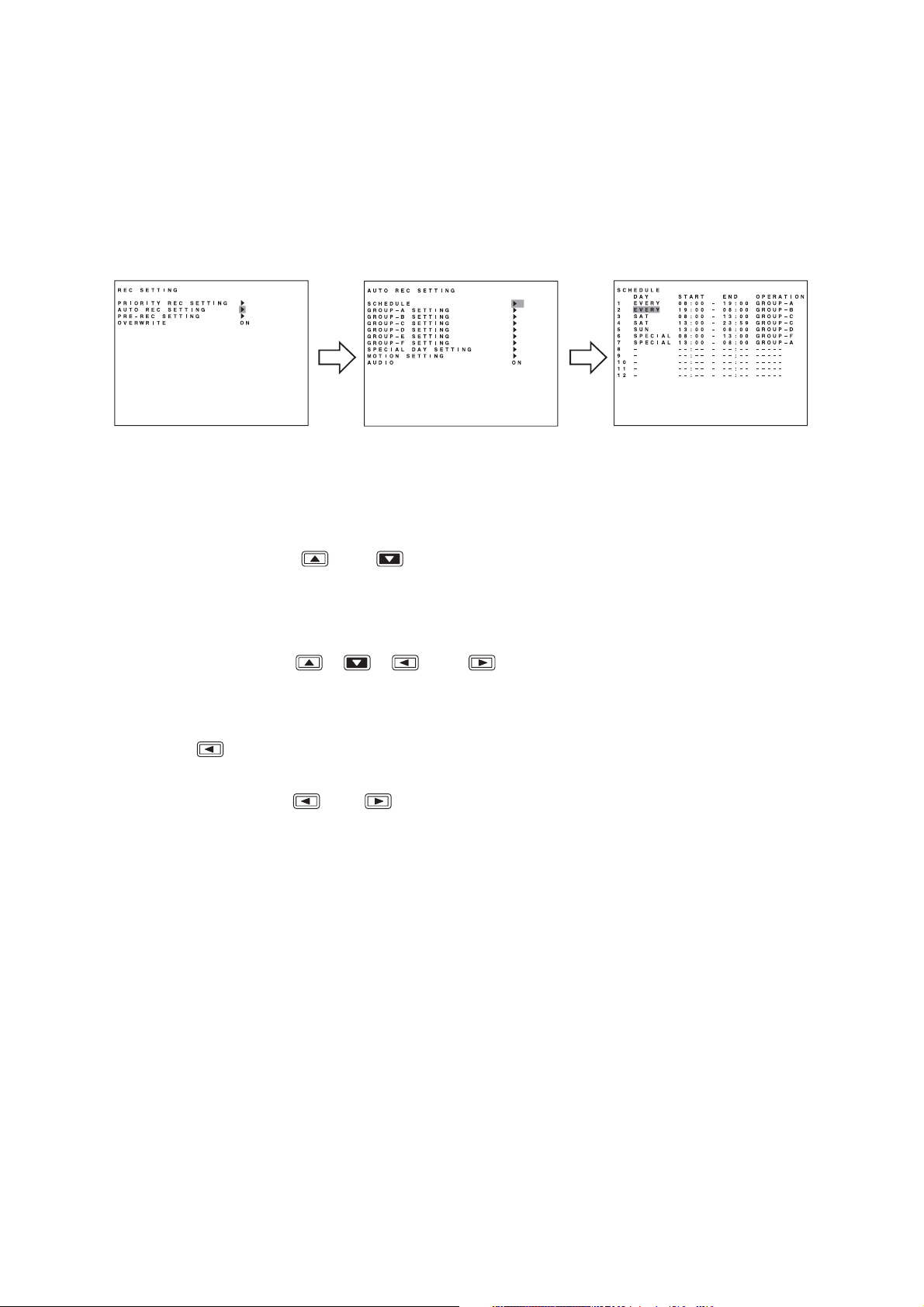
29
1. Hold down the Menu key for 2 seconds or more.
The main menu screen is displayed.
2. Select "REC SETTING," then press the Menu key. The Recording setting screen is displayed.
3. Move the cursor with the [ ] and [ ] keys to select "AUTO REC SETTING," then press the Menu
key.
The Auto-recording setting screen is displayed.
4. Select "SCHEDULE," then press the Menu key.
5. Move the cursor with the [ ], [ ], [ ], and [ ] keys and perform schedule setting using the [+]
and [-] keys.
Set a day of the week, Start time, End time and manner of operation (group setting). (Refer to p. 79; Autorecording setting.)
6. Press the [ ] key while the cursor is set to the leftmost selection item on the screen.
The indication will appear to ask whether or not to save the setting.
7. Move the cursor with the [ ] and [ ] keys to select "YES," then press the Menu key.
The display reverts to the auto-recording setting screen.
12.4. Auto-Recording Settings
Recordings are normally performed according to the preprogrammed schedule. Therefore, perform schedule
or group settings when making auto-recording. (Refer to p. 79; Auto-recording setting.)
12.4.1. Schedule setting
Set the schedule (Day, Start time, and End time) for each group to operate.
Menu key Menu key
Page 30
30
12.4.2. Setting the group
Perform individual settings such as Normal recording and Alarm Event recording for Group A - F.
1. Choose "Group A-F" from the Auto-recording Settings and press the Menu key.
The Group setting screen is displayed.
2. Move the cursor with the [ ], [ ], [ ], and [ ] keys and perform Group setting using the [+]
and [-] keys.
For a detailed information, refer to "Group A-F settings." (Refer to p. 80; Setting of groups A – F.)
3. Press the [ ] key while the cursor is set to the leftmost selection item on the screen.
The indication will appear to ask whether or not to save the setting.
4. Move the cursor with the [ ] and [ ] keys to select "YES," then press the Menu key.
The display reverts to the auto-recording setting screen.
12.4.3. Other settings
In Auto-Recording Settings, "special day," "motion detection," and "audio (ON/OFF)" settings can be
performed in addition to both schedule and group settings. (Refer to p. 79; Auto-recording setting.)
AUTO REC SETT ING
SCHEDULE
GROUP –A S ET T I NG
GROUP –B S ET T I NG
GROUP –C S ET T I NG
GROUP –D S ET T I NG
GROUP –E S E TT I NG
GROUP – F SE T T I NG
SPECI AL DAY SET T I NG
MOT I ON S E T T I NG
AUD I O ON
Menu key
GROUP –A S ET T I NG
NORMAL REC S ET T I NG
ALARM EVENT REC SETT I NG
ALARM EVENT REC MODE SEQUENCE
ALARM I NPUT MODE EDGE
POST ALARM TIME 999SEC
MOTI ON DETECT MODE LEVEL
POST MOTION TIME 1SEC
Page 31

31
13. MONITOR DISPLAY
Functions that can be displayed differ between Monitor Outputs 1 and 2.
13.1. Monitor Switch
Operations of Monitor 1 and Monitor 2 outputs switch with each depression of the Monitor key.
Monitor 1 output is enabled when the Monitor key is unlit, and Monitor 2 output is enabled when the Monitor
key is lit.
13.2. About Live and Playback Modes
Display can be switched between live and playback modes
Pressing the Play key when in live mode switches the screen to playback mode, while pressing the Stop key
when in playback mode switches the screen to live mode. The multi-segment split screen display is
maintained even if the mode is switched.
Live mode: Displays current camera images. The camera number is displayed following the "L" indication.
Playback mode: Displays recorded camera images. The camera number is displayed following the "PB"
indication.
Function
Monitor output 1
Monitor output 2
Function
Monitor output 1
Monitor output 2
* Only the C-DR161D(16-channel versions) can display.
Full
4 Seg
Digital Recorder
menu
Live mode
9 Seg
Search
menu
16 Seg* Sequence
Display position
setting screen
Full 9 Seg
Playback mode
4 Seg
Triplex setting
screen
16 Seg*
Archive
menu
Electronic
Zoom
Cascade
output
; Enable
; Disable
Page 32

32
(1) Camera number
"L" represents the live pictures. The number
indicates the input number of the camera
images.
(2) DVR name
(Refer to p. 89; DVR name setting.)
(3) Recording status
: Indicates that normal recording is in
progress.
ALARM: Indicates that alarm recording is in
progress. The number is an alarm
input terminal number.
MOTION:Indicates that motion detected
recording is in progress. The number
is a camera number that detects
motions.
PRIOR: Indicates that priority recording is in
progress.
(4) Audio recording ON/OFF
: Audio recording enabled.
(Refer to p. 77; Priority recording setting.)
(Refer to p. 79; Auto-recording setting.)
(Refer to p. 85; Pre-recording settings.)
[No indication]: Audio recording disabled.
(5) Overwrite settings
(Refer to p. 76; Recording setting.)
: Write Protect
: Overwrite
(6) Disk mode
(Refer to p. 102; Hard disk drive initialization.)
M: Mirror mode
[No Indication]: Normal mode
(7) Camera name
(Refer to p. 89; Camera name setting.)
(8) Available hard disk time
Displayed when in Write Protect mode.
(9) Fan failure
The " " indication lights when the fan fails.
This indication cannot be set to "Hide" in screen
display settings.
(10) Hard disk in use
Indicates the hard disk currently making
recording.
A, B *
1
: Built-in hard disk
C, D: Disk Array
(Disk array connection terminal 1)
E, F: Disk Array
(Disk array connection terminal 2)
*
1
One of "A"-"F" is displayed during normal
mode. Two characters from "A"-"F" are
displayed during mirror mode.
(11) Current date and time
(Refer to p. 100; Date/Time setting.)
This position can be moved by settings.
Notes
• Either (1) or (7) can be displayed.
• All indications but (9) can be set to Display/Hide by
menu.
13.3. Display When In Live Mode
The following indications appear when in live mode.
1
L1
DVR NAME
ALARM M 1D1 2H AB
2
SAT JAN / 01 / 05
CAM NAME
0:00:00
11
3
5
6 8
4
7
9
10
Page 33

33
(1) Camera number being played back
"PB1" represents playback image. The number
represents the input number of the camera
images.
(2) DVR name
(Refer to p. 89; DVR name setting.)
(3) Playback mode
PLAY: Playback in progress.
PLAY: Fast forward quick playback in
progress.
REV: Reverse playback in progress.
REV: Fast reverse playback in progress.
PAUSE: Playback temporarily stops.
(4) Fast forward/reverse playback speed
X2, X4, X8: Quickly plays back forward or in
reverse at the indicated speed.
1M, 10M: Quickly plays back forward or in
reverse skipping images in 1-minute/10-minute
segments.
(5) Recording state
: Priority recording or Auto recording in
progress
[No indication]: Recording stop state
(6) Camera name
(Refer to p. 89; Camera name setting.)
(7) Fan failure
The " " indication lights when the fan fails.
This indication cannot be set to "Hide" in screen
display settings.
(8) Hard disk being played back
A: Plays back the first built-in hard disk.
B: Plays back the second built-in hard disk.
C -: Plays back the Disk Array's hard disk.
(9) Recording date and time
This display position can be changed by settings.
Notes
• Either (1) or (6) can be displayed.
• All indications but (8) can be set to Display/Hide by
menu.
13.4. Display during Playback
The following indications appear while the playback screen is displayed:
13.5. Full-Screen Display
Pressing the Camera Selector key while in live or playback mode displays the selected camera output on the
full screen.
1
PB1 SAT JAN / 01 / 05
DVR1
2
PLAY 2 A
3 4
CAM1
5
6 7
0:00:00
9
8
L1 L2 L3
L4 L5 L6
L7 L8 L9
SAT JAN / 01 / 05
0:00:00
Press the Camera
Selector key No. 3.
AB
L3
SAT JAN / 01 / 05
0:00:00
AB
Page 34

34
13.6. Multi-Segment Split-Screen Display
When the live or playback screen is displayed, the multi-segment split-screen display changes as shown
below each time the Multi-Screen key is pressed. Multi-Screen key lights continuously during multi-Segment
Split-Screen display.
9-channel DVR :
4 Seg A 4 Seg B
9 Seg 4 Seg C
4 Seg A 4 Seg B 4 Seg C 4 Seg D
16 Seg 9 Seg B 9 Seg A
(Example) Screen display in live mode (9-channel DVR)
4-segment split A
L1 L2
L3 L4
L1 L2 L3
L4 L5 L6
SAT JAN / 01 / 05
0:00:00
AB
Press the
Multi-Screen key.
SAT JAN / 01 / 05
0:00:00
Press the
Multi-Screen key.
Press the
Multi-Screen key.
16-channel DVR:
4-segment split B
L5 L6
L7 L8
4-segment split C9-segment split
L9 L1
L2 L3
SAT JAN / 01 / 05
0:00:00
AB
Press the
Multi-Screen key.
SAT JAN / 01 / 05
0:00:00
L7 L8 L9
AB
AB
Page 35

35
(Setting Example)
Step 1 : Camera 1 3 seconds
Step 2 : Camera 2 3 seconds
Step 3 : Camera 3 3 seconds
Step 4 : 4-split A 3 seconds
Note
That when the screen is switched, the
picture may be distorted momentarily.
1. Press the zoom key.
The zoom selection screen is displayed. The pointer is displayed on the screen.
2. Move the central point of the subject to be zoomed using the [ ], [ ], [ ], and [ ] keys, then
press the Menu key.
The subject can be zoomed with the designated point at the center. Zoomed areas can be moved using the
[ ], [ ], [ ], and [ ] keys even while zoomed.
3. Press the Menu key when the zoom screen is displayed.
The display reverts to the zoom selection screen. Pressing the Zoom key again when the zoom screen is
displayed resets the zoom display.
Note
When channels are changed, multi-segment split-screen display is selected, or a search function is operated
during zoom display, the zoom mode is reset.
13.7. Sequence Display
Camera live images are displayed in sequential order when the Sequence key is pressed while in live mode.
Viewing intervals and cameras to be displayed can be set on the menu screen. Sequence key lights
continuously during Sequence display. (Refer to p. 88; Sequence setting.)
13.8. Zoom Display
Live or recorded full-screen images can be viewed in 2 x zoom display. Zoom key lights continuously while the
Zoom selection screen or Zoom screen is displayed.
Step 1
L1
SAT JAN / 0 1 / 05
0:00:00
3 seconds elaps
Step 2
L2
SAT JAN / 0 1 / 05
0:00:00
AB
Step 4
L1 L2
L3 L4
3 seconds elaps
SAT JAN / 0 1 / 05
0:00:00
AB
Step 3
L3
3 seconds elaps
3 seconds elaps
SAT JAN / 0 1 / 05
0:00:00
Live or play back screen
Zoom key
Zoom selection screen Zoom screen
Menu key
AB
AB
Zoom key
Menu key
Zoom key
Page 36

36
L
14. OTHER FUNCTIONS
14.1. Triplex Display
Holding down the Multi-Screen key for 2 seconds or more during playback, including fast forwarding,
rewinding, and pause, on the multi-segment split screen switches the display to Triplex setting screen. The
Triplex setting permits live camera images to be viewed among recorded images displayed on the multisegment split screen. The Triplex setting is maintained even when the power is switched OFF.
1. Hold down the Multi-Screen key for 2 seconds or more.
The triplex setting screen is displayed.
2. Press the [ ], [ ], [ ], and [ ] keys to move the cursor.
3. Press the Camera selector key.
When the Camera selector key is pressed, the live screen corresponding to the selected camera output is
displayed in the position indicated by the cursor. A dark screen is displayed if the selected camera is not
connected.
4. To revert the set live images to the playback images, press the Sequence key.
Pressing the Sequence key resets the selected position's live display and switches it to the playback image.
5. Hold down the Menu key for 2 seconds or more.
The triplex setting screen is terminated.
Notes
• It is impossible to set all screens to the live display.
• Two or more live image screens cannot be set for the same camera.
During playback Triplex setting screen
Hold down the Multi
-Screen key for
2 seconds or more
PB1 L5
TRI PLEX SETTI NG
5PB1 PB2
PB3 PB4
Hold down the
Menu key for
2 seconds or more
PB3 PB4
Page 37

37
1. Hold down the Multi-Screen key for 2 seconds or more.
The position setting screen is displayed.
2. Press the [ ], [ ], [ ], and [ ] keys to move the cursor.
3. Press the Camera selector key.
When the Camera selector key is pressed, the live screen corresponding to the selected camera output is
displayed in the position indicated by the cursor. A dark screen is displayed if the selected camera is not
connected.
4. Hold down the Menu key for 2 seconds or more.
When the Menu key is pressed, the setting screen is terminated in the current state, returning the display to
the live screen.
Notes
• If live picture of selected camera number is already displayed on the position setting screen, it is switched
with the live screen of the camera during selection.
• Position of camera images through Monitor 2 cannot be changed.
• When an alarm event occurs during display position setting, the alarm-activated camera image is recorded
but not displayed on the full screen.
L
1
14.2. Position Setting Display
Holding down the Multi-Screen key for 2 seconds or more when the live multi-segment split screen is
displayed displays the position setting screen. Camera images can be displayed at arbitrary positions on the
multi-segment split screen. The position setting for each multi-segment split screen is saved.
During Live images are displayed Position setting screen
L1 L2
Hold down the Multi
-Screen key for
2 seconds or more
L1 L2
POS I T I ON S ET T I NG
L3 L4
Hold down the
Menu key for
2 seconds or more
L3 L4
Page 38

38
15. RECORDING
15.1. Before Recording
Auto-recordings are normally performed according to the preprogrammed schedule. Operations to start
recording such as pressing the key are not required. You can also make recording by pressing the Priority
Recording key outside the scheduled time period. Perform disk mode and overwrite settings before recording.
15.1.1. Disk mode
Normal and mirror modes are available to this mode. (Refer to p. 101; Equipment maintenance.)
Notes
• When the disk mode is changed, the hard disk is initialized, causing the recorded images to be erased. Be
sure to determine the disk mode before use.
• Unless the disk mode setting is performed, mirror recording cannot be performed as the hard disk is factory-
preset to normal mode.
Normal mode: When the first hard disk finishes recording, the second hard disk automatically begins to
record. When the settings (recording rate and picture quality) of both normal and mirror
modes are set to be identical, the recording time for normal mode is about twice that of
mirror mode. The total recording rate is 100 IPS maximum.
Mirror mode: The same image is simultaneously recorded on both hard disks. Even if one of the two
hard disks fails, the other hard disk continues to record, allowing all recorded images to be
played back. The total recording rate is 50 IPS maximum. Set the disk mode to Mirror
when performing mirroring by the two built-in hard disks or when performing mirroring by
the built-in hard disk and the Disk Array.
Note
When the hard disk expansion unit is connected, intermissive audio reproduction may occur when playback is
performed during recording. In such cases, decrease the live image transmission picture quality of the network
settings, recording picture quality of the recording settings, or the recording rate.
15.1.2. Recording order to hard disks
Recordings to the built-in hard disks are performed in the following order.
Note
For the recording operation when the Disk Array is connected, refer to the instruction manual enclosed with
the Disk Array.
Normal mode Mirror mode
HDD A
HDD A
HDD B
HDD B
Page 39

39
15.1.3. Disk recording mode
Overwriting of hard disk recordings can be set to Overwrite or Write Protect. (Refer to p. 76; Recording
setting.)
Overwrite: When all hard disks become full, previous recorded older data is automatically deleted and
replaced with newer data.
Write Protect: When all hard disks become full, recording is stopped. To begin recording again, initialize the
hard disk and reactivate the Digital Video Recorder, or set the disk-recording mode to
"Overwrite."
15.2. Recording Mode
The following recording modes are available to the Digital Video Recorder. Priorities are (1), (2) and (3) in that
order.
15.3. Priority Recording
Priority recording is given higher priority over Auto-recording. Use this recording mode to check recording
details when, for example, a suspicious person intrudes or when making recording outside the scheduled time
period. In the Priority Recording settings, the following settings can be made for individual cameras: recording
ON/OFF, recording rate, picture quality and audio ON/OFF. (Refer to p. 77; Priority recording setting.)
15.3.1. How to perform priority recording
1. Press the Priority Recording key to start the priority recording. To stop a buzzer sound, press the Buzzer
Stop key.
2. Hold down the Priority Recording key for 2 seconds or more to terminate the priority recording.
Notes
Priority recording can be started by any of the following ways.
• Input the signal to the Priority recording input terminal on the rear panel.
• Press the Remote Controller's Priority Recording key.
Recording mode
Priority Recording 1
Auto-recording
(operation according
to the schedule)
Pre-Alarm recording
(operates only in recording stop mode)
Alarm event recording 2
Normal recording 3
Alarm-input recording
Motion-detected recording
Page 40

40
15.4. Auto Recording (Alarm Event Recording and Normal Recording)
With auto-recording, recordings are made according to a preset schedule, which can include up to twelve
different programs. If one or more programs have duplicate execution times, the program with a largest
number takes precedence. Settable items for each program include: Day of the Week; Start/End Times; and
Operation. Up to six settings groups, named A through F, can be made for "Operation," and recording settings
for Normal and Alarm recording can also be registered. Further, up to sixty "special day" operational settings
can also be made, with operation controlled by different programs, motion detection areas for individual
cameras, and audio recording during auto- recording. (Refer to p. 79; Auto-recording setting.)
Notes
• If the Alarm display interval is set to "0" second, no full-screen display is performed and the current display
status is maintained.
• If an alarm event occurs outside the scheduled time period, Alarm Event recording is not performed.
15.4.1. Alarm event recording
Alarm Event recording includes both "Alarm Input" and "Motion Detection" recording. For Alarm Event
recording, settable items for each individual camera include: Recording ON/OFF; Recording Rate; and Picture
Quality. It is also possible to set, for each recording mode, the type of events that will cause recording to
begin. (Refer to p. 82; Alarm event recording setting.)
For Alarm Event recording mode, it is possible to set the type of recording operation to be performed when
multiple events have occurred simultaneously. Setting the mode to "Sequence" allows two or more events to
be set for individual cameras. For Alarm Input recording time, set both alarm input mode and post alarm time
intervals. For Motion Detection, set both motion detection mode and post-motion alarm time. (Refer to p. 80;
Setting of groups A-F.)
When an alarm event occurs, the corresponding camera’s image is switched to full-screen display until the
preset alarm time interval has elapsed, after which the display reverts to the original screen display. (Refer to
p. 86; Screen display setting.)
Alarm input recording: Alarm Input recording begins when signals are received at the alarm input
terminal on the rear panel. Use event settings to set cameras to be recorded. If
"Sequence" is selected, up to four alarm input terminals can be set optionally
per camera. If "Last" is selected, the "Alarm ON/OFF" can be set only for the
alarm input terminal with a number corresponding to that of the camera.
Motion detected recording: Motion Detection recording begins when motion is detected in a camera image.
Use Motion Settings to set the motion detection area, sensitivity, and activation.
Use event settings to set cameras to be recorded. If "Sequence" is selected as
the alarm event recording mode, then up to four alarm input terminals can be
set optionally per camera. If "Last" is selected, the "Alarm ON/OFF" can be set
only for the alarm input terminal with a number corresponding to that of the
camera.
15.4.2. Normal recording
This function automatically records camera images set by schedule. For Normal recording, settable items for
each individual camera include: Recording ON/OFF; Recording Rate; and Picture Quality. (Refer to p. 81;
Normal recording setting.) Recordings can be made on scheduled patterns like "day and night," and
"weekdays and holidays" by combining two or more programs.
Page 41

41
15.6. Recording State
The Digital Video Recorder permits recordings to be set to best meet user requirements.
[ Auto recording (Normal recording) ]
Recording is performed as shown in the following figure when set to always automatically record (Normal
recording).
Recording within a scheduled time period
(1) Priority recording is initiated if Priority recording's event occurs.
(2) When the Priority recording ends, recording reverts to Normal
recording mode.
(3) Alarm Event recording is initiated if the alarm input terminal
receives a signal or if motion movement is detected.
(4) When the preset Alarm Event recording interval elapses, recording
reverts to Normal recording mode.
(5) Priority recording is initiated if a Priority signal is received or if
manually started during Alarm Event recording.
(6) When the Priority recording ends, recording reverts to Normal
recording.
Notes
• Perform Normal recording settings in auto recording settings.
• Normal recordings are factory-preset to "recordings ON" for all
cameras.
15.5. Pre-Recording
This function records images immediately before Priority recording or Alarm Event recording is initiated.
Setting the Pre-Recording interval to 1 second or more allows Pre-Recording to be performed. In PreRecording, the recording rate and picture quality cannot be individually set for each camera. Instead,
recording rate, picture quality, and audio ON/OFF settings are common to all connected cameras. The
maximum recording rate per camera is 3 IPS. (Refer to p. 85; Pre-recording settings.)
Pre-Recording can be performed under the following conditions.
• When Priority recording begins while recording is stopped.
• When an alarm event occurs and alarm even recording begins while a schedule in which Normal Recording
is not available but Alarm Event Recording is available is in operation.
Note: Pre-Recording cannot be performed during Normal Recording.
Priority recording
1
Priority recording
start
Normal recording
2
End
Start
5
End
6
3
Alarm event
start
4
End
Alarm event recording
Alarm input recording
Motion-detected recording
Page 42

42
(1) When the Priority recording's event occurs, Pre-Recording is first made,
then Priority recording begins.
(2) When the preset Priority recording interval elapses, recording reverts to
recording stop mode.
Notes
• Normal recording and Alarm event recording cannot be performed.
• If Priority recording is initiated, Pre-Recording is first made, then Priority
recording begins.
• Pre-Recording is initiated when the Pre-Alarm interval is set to 1 second
or more.
(1) If the Priority recording's event occurs, Pre-Recording is first
made, then Priority recording begins.
(2) When the Priority recording ends, recording reverts to recording
stop mode.
(3) If Alarm Event recording is initiated, Pre-Recording is first made,
then Alarm Event recording begins.
(4) When the preset Alarm Event recording interval elapses, recording
reverts to recording stop mode.
(5) Priority recording is initiated if a Priority signal is received or if
manually started during Alarm Event recording.
(6) When the Priority recording ends, recording reverts to recording
stop mode.
Notes
• Even if Priority recording or Alarm recording is initiated, it is made
following Pre-Recording.
• Pre-Recording is initiated when the Pre-Alarm interval is set to 1
second or more.
[ Recording only when Priority recording is initiated or alarm event occurs ]
To stop recording within the scheduled time period, set all cameras to "Recording OFF" in normal recording
settings. To perform recording only when Priority recording or Alarm Event recording is initiated, recording is
performed as shown in the following figure.
Recording within a scheduled time period
[ Recording only when Priority recording is initiated ]
Recording is performed as follows outside the scheduled time period.
Recording outside scheduled time periods
Priority recording
Priority recording
start
Pre-Alarm
1
recording
Pre-Alarm
recording start
Recording stop
Pre-Alarm
recording start
Pre-Alarm
3
recording
Alarm event
start
2
End
End
Start
5
4
End
6
Alarm event recording
Alarm input recording
Motion-detected recording
Priority recording
Priority recording
start
Pre-Alarm
1
recording
Pre-Alarm
recording start
2
End
Recording stop
Page 43

43
15.7. Recording Operation When Edge/Level Settings Are Performed
When Priority Recording Input mode, Alarm Input mode, or Motion Detection mode are set to either "Edge" or
"Level," recording will be performed as follows.
15.8. Picture Quality
Picture quality can be set at any of five different levels for each recording mode and camera. File sizes for
each picture quality are shown below.
Note: File size may differ depending on the images.
Notes
• Pre-recording only functions when recording is stopped. It cannot be used when recording is in progress.
• If the Priority Recording Key on the Digital Video Recorder or remote controller is used to start recording
when Priority Recording Input mode is set to "Level," then priority recording continues until it is manually
stopped.
[ Edge ] [ Level ]
ON
Priority Recording Input
Alarm Input
Motion Detection
ON OFF
Recording Status
1
Pre-Recording
2
Priority Recording, Alarm Input Recording, or Motion Detection Recording
12
Pre-Recording
Time
Post Recording
Time
1
Pre-Recording
Time
2
Post Recording
Time
Picture Quality File Size
1 (Highest)
2
3
4
5 (Lowest)
64 KB
40 KB
32 KB
24 KB
16 KB
Page 44

44
15.9. Recording Rate
The recording rate indicates the number of images to be recorded per second and is expressed by the unit
IPS (Image Per Second). In the Digital Video Recorder, the total recording rate is the sum of each camera’s
recording rate and recordings can be made for up to 100 IPS in normal mode and for up to 50 IPS in mirror
recording mode. The maximum recording rate that can be set per camera is 50 IPS.
The recording rate to be set on the menu screen is displayed, rounded up. The following table shows the
relationship of menu screen display vs. actual recording rate.
The total recording rate is calculated by the actual recording rate in the above table. If, for example, each of
16 cameras is set to a menu screen display value of 6 IPS, the total recording rate is 100 IPS since the actual
per-unit recording rate is 6.25 IPS.
Also, if a recording rate of 1/2.5 IPS or less (1/2.5
-
1/60) is designated, the total rate is calculated using the
rate of 0.78125.
15.10. Recording time
Recording time varies depending on the settings described below.
For recording time, refer to p. 117, "Recording time table" as a guide.
• HDD Capacity
• Recording rate (50 - 1/60)
• Picture quality (1 - 5)
• Audio (ON/OFF)
15.11. Available Disk Time and Operation
When disk recording mode is set to "Overwrite," the available time indication is not displayed and the disk
space indicator does not light. In "Write Protect" mode, when the remaining time is shorter than the preset
remaining warning time, the disk space indicator lights and recording is stopped.
Menu screen display
50
25
13
6
3
1
1/2.5
Actual recording rate
50.000000
25.000000
12.500000
6.250000
3.125000
1.562500
0.390625
Menu screen display
1/4
1/5
1/10
1/20
1/30
1/60
Actual recording rate
0.260417
0.195313
0.097656
0.048828
0.033967
0.016622
Page 45

45
16. PLAYBACK
16.1. Type of Playback
The Digital Video Recorder is equipped with the simultaneous recording/playback function that permits
recorded images to be played back without stopping recording. Playback is performed only through Monitor 1.
The following playback methods are available.
16.2. How to Perform Playback
Performing playback operation during live mode switches the display to the playback mode.
Notes
• If power is turned off, the playback starts from the earliest image.
• Playback performance could be degraded during live transmission, playback transmission or downloading
using the PC's Web browser.
16.2.1. Playback
Press the Play [ ] key.
Recorded images are played back. The Playback key lights green, displaying the playback screen.
When playback is performed again, playback begins from the time at which it last stopped.
16.2.2. Reverse playback
Press the Reverse Play [ ] key.
Plays back recorded images in reverse chronological order. The Reverse Play key lights green, displaying the
reverse playback screen.
When reverse playback is performed again, it begins from the time at which it last stopped.
16.2.3. Playback stop
Press the Stop [ ] key.
Stops pictures being played back. Stopping the playback switches the display to the live mode.
Type
Playback
Reverse playback
Earliest image playback
Latest image reverse playback
Fast forward/reverse playback
Pause
Frame advance/reverse playback
Instant event access playback
Description
Plays back recorded images.
Plays back recorded images in reverse chronological order.
Plays back from the earliest recorded image.
Plays back in reverse from the most recent recorded image.
Plays back recorded images forward or in reverse at 2x, 4x or 8x speed. Playback
speed can be increased using the 1-minute/ 10-minute skip playback function.
Temporarily stops playback and displays still pictures.
Plays back images in pause on a frame by frame basis.
Moves to the event start time (Priority recording, Alarm Event recording and Normal
recording) to begin playback.
( )
Page 46

46
16.2.4. Earliest image display
Press the Play [ ] key while holding down the Playback Stop [ ] key.
Playback begins from the time at which the earliest image was recorded.
16.2.5. Latest image reverse playback
Press the Reverse Play [ ] key while holding down the Playback Stop [ ] key.
Reverse playback begins from the time at which the latest image was recorded.
16.2.6. Fast forward/reverse playback
Press the Play [ ] key (Reverse Play [ ] key when in reverse playback mode) during playback.
Fast forward playback (fast reverse playback when in reverse playback mode) is initiated. Playback speed
cycles through 2X, 4X and 8X whenever the key is pressed. The speed can be increased using the 1-minute
or 10-minute time skip function.
Notes
• The 1-minute/10-minute skip function may not operate correctly if recordings are made with the clock turned
back.
• Recorded images may not be played back at the indicated speed depending on the hard disk access time,
etc.
• For the pre-recorded recording data, it cannot playback skips forward in 1-minute/10-minute segments.
16.2.7. Pause
1. Press the Pause [ ] ( ) key during forward or reverse playback.
Playback is temporarily stopped and the key lights green.
2. To perform playback or reverse playback again, press the Play [ ] key or Reverse Play [ ] key.
Pause mode is cancelled and forward or reverse playback begins again.
16.2.8. Frame advance/reverse playback
Press the Play [ ] key or Reverse Play [ ] key with the Pause [ ] ( ) key pressed, while
recording is temporarily stopped.
Frame advance or reverse playback is performed per screen whenever the key is pressed.
( )
Playback speed
Normal speed 2 times (X2) 4 times (X4) 8 times (X8)
10-minute time skip (X10 minute) 1-minute time skip (X 1 minute)
( )
Page 47

47
[Instant access to the previous event]
Hold down the Reverse Play [ ] key for 2 seconds or more while playback is temporarily stopped.
Playback advances to the beginning of the current event and temporarily stops.
16.3.1. Instance event access
Recording moves to the event start time (Priority recording, Alarm Event recording or Normal recording) and
temporarily stops. Playback images can be moved from event to event and required images can be quickly
searched.
[Instant access to the next event]
Hold down the Play [ ] key for 2 seconds or more while playback is temporarily stopped.
Playback advances to the beginning of the next event and temporarily stops.
16.3. Event
Events that can start recording include Priority recording, Normal recording, Alarm input recording, and Motion
detection recording. Each event can be confirmed using the recording log. (Refer to p. 98; Recording log.)
Hold down the [ ] key for 2 seconds or more while recording is temporarily stopped.
Instant Event Access
Event Event Event
Playback direction
Hold down the [ ] key for 2 seconds or more while recording is temporarily stopped.
Instant Event Access
Event
Event
Playback direction
Event
Page 48

48
FEB
1. Press the Search key.
The Search screen is displayed.
2. Select "DATE/TIME SEARCH," press the Menu key.
Date/Time search screen is displayed.
3. Move the cursor with the [ ] and [ ] keys and perform
clock settings using the [+] and [-] keys. Set year, month,
date, hour, minute, and second.
4. Move the cursor to "EXECUTE" and press the Menu key.
Images recorded at the time closest to the designated time
are displayed.
5. To exit the searching and return to the previous screen, press
the [ ] key at the leftmost parameter position of the
screen.
17. SEARCH
Pressing the Search key in the live mode or in the playback mode displays the search screen. Two search
methods are available: Date/time search by designating the specific time, and event search by designating the
event.
Note
It may take a relatively long time to search (During recording, Web playback distribution, Web download or
Disk Array connection). It also takes time to search if a lot of event numbers exist.
17.1. Date/Time Search
Entering the date and time to perform a search displays all camera images recorded closest to the designated
time in freeze-frame on the 16-segment (or 9-segment) split screen display. If no recording is made on the
designated date and time, the date and time closest after the designated date and time is displayed. The
oldest and newest times for recorded data are displayed, so please enter dates and times occurring between
these.
Search
Menu item Setting item
Date/Time search
Event search
Time
Camera
Event
Start time
End time
SEARCH
DATE/TIME SEARCH
EVENT SEARCH
DATE/TIME SEARCH
DATE/TIME FEB/24/05 05:00:00
SEARCH EXECUTE
REC START FEB/24 / 05 05 : 00: 00
REC END FEB /25 / 05 05: 00: 00
Item
DATE / TIME
Selection
JAN / 01 / 00 00:00:00
DEC / 31 / 99 23:59:59
SEARCH Search begins if “Execute” is selected.
EXECUTE
REC START Displays the time for the oldest video recording.
REC END Displays the time for the newest video recording.
SEARCH SCREEN
DISPLAY TIME
Description
-
Designate the date and time to research.
Displays the time at which the search screen was displayed.
SEARCH SCREE N D I SPLA Y T I ME
FEB /24 / 05 05: 00: 00
Page 49

49
17.2. Event Search
The event search begins under the designated conditions.
C
AM1
1. Press the Search key.
The search screen is displayed.
2. Select "EVENT SEARCH," then press the Menu key.
Event search screen is displayed.
3. Move the cursor with the [ ], [ ], [ ], and [ ]
keys, and perform camera, event, start time and end time
settings using the [+] and [
-
] keys.
4. Move the cursor to "EXECUTE," then press the Menu key.
Event search list is displayed.
5. Move the cursor using the [ ] and [ ] keys, select the
desired event from the event search list, and then press the
Menu key. The image at the event start time is displayed in
freeze-frame on the 16-segment (or 9-segment) split screen
display.
An error message is displayed at upper right of the screen if
images does not exist after the designated time.
Pressing the Menu key moves the cursor to the previous
position.
An error message is displayed if an event corresponding to the
designated conditions does not exist. Pressing the Menu key
moves the cursor to the previous position.
Notes
• In some cases, changing the current time may make it impossible to search by time when duplicate time
data exists in the hard disk.
• When recording with overwrite permission, recorded images are overwritten three minutes after the time
search screen has been displayed, making it impossible to search or display data in the vicinity of the oldest
time. Refer to Search Screen Display Time.
NOTHING FOUND OK
EVENT SEARCH
CAMERA CAM1
EVENT MOT ION
START T IME JAN/ 1 / 0 5 00 :0 0 : 00
END T IME J AN/ 2 / 0 5 23 : 55 : 59
SEARCH EXECUTE
SEARCH SCREE N D I SPLA Y T I ME
FEB /24 / 05 05: 00: 00
NOTHING FOUND OK
Item
CAMERA
EVENT
START TIME Designate the search start time. It is not possible to enter
Selection
CAM 1-16 / ALL
PRIORITY / NORMAL /
ALARM / MOTION / ALL
JAN / 01 / 00 00:00:00
-
DEC / 31 / 99 23:59:59
Description
Select the camera number to search.
Select the event type to search.
a start time value that is greater than that of the end time.
END TIME
JAN / 01 / 00 00:00:00
-
DEC / 31 / 99 23:59:59
EXECUTE
Designate the search end time. It is not possible to enter
an end time value that is smaller than that of the start time.
Search begins if Execute is selected.SEARCH
Indicates the time when the search screen is displayed.SEARCH SCREEN
DISPLAY TIME
Page 50

50
PRIORMAFEB/
8/0
5
1
:
0:0
0
(1) Camera number
01
-
16 (01-09
)
(2) Type of Event recorded
NORMAL: Normal recording
ALARM: Alarm recording
MOTION: Motion detected recording
PRIOR: Priority recording
(3) Disk mode
M: Mirror mode
[No indication]: Normal mode
(4) Recorded hard disk
A, B: Built-in hard disk
C, D: Disk Array
(Disk array connection terminal 1)
E, F:: Disk Array
(Disk array connection terminal 2)
(5) Recording start date and time
(6) Multiple pages
Displays if event lists extend to multiple pages.
: Previous page exists.
: Next page exists.
17.2.1. Event search list display
If an event searching corresponds to the event recorded on the designated conditions, an event list is
displayed.
2
1
EVENT SEARCH
CH E VEN T M HD STAR T T I ME
0 5
05 PRIOR M A FEB/ 28 / 05 1: 00: 00
01 MOT ION A FEB / 28/ 05 11: 00: 00
-- ------ - - ---/--/-- --:--:--
-- ------ - - ---
-- ------ - - ---
-- ------ - - ---
-- ------ - - ---/--/-- --:--:--
-- ------ - - ---
-- ------ - - ---/--/-- --:--:--
-- ------ - - ---
-- ------ - - ---
-- ------ - - ---/--/-- --:--:--
-- ------ - - ---
-- ------ - - ---
-- ------ - - ---
-- ------ - - ---
-- ------ - - ---
-- ------ - - ---/--/-- --:--:--
4
3
5
2
/--/
-- --:--:--
/--/
-- --:--:--
/--/
-- --:--:--
/--/
-- --:--:--
/--/
-- --:--:--
/--/
-- --:--:--
/--/
-- --:--:--
/--/
-- --:--:--
/--/
-- --:--:--
/--/
-- --:--:--
/--/
-- --:--:--
0
6
Page 51

51
18. ARCHIVE
The Digital Video Recorder is equipped with an archive function that transfers image data recorded on the
hard disk to DVD-R disk or USB memory. Camera image data designated between start position and end
position can be archived. Since dedicated viewer software is also downloaded at the same time, archived
images can be easily played back on a PC.
Note
Archive operation can be performed only at the operation level 1. When the security has been set, perform
archive operation after login to the Operation Level 1.
Two methods can be used to designate the archiving range.
• Designate the archiving range after entering date and time.
• Designate the archiving range while viewing the playback image.
[ Archiving to USB memory devices ]
Notes
• Connect the USB memory device to the copy terminal of the Digital Video Recorder.
• Only mass storage class devices (those recognized as "USB mass storage memory devices" under
Windows 2000/XP/Vista) can be used.
• Compatible with USB 1.1 devices only. Not compatible with USB 2.0 devices.
• USB memory devices formatted with FAT12/FAT16 can only be used.
• It is not possible to play back video files copied to the USB memory device on the Digital Video Recorder.
Connect the USB device to a PC and use viewer software to play back files.
• If USB memory is removed when USB archive is in progress, the Digital Video Recorder will then be unable
to recognize USB memory. Be sure to remove it after finishing archiving or after archive operation is
stopped.
[ Archiving to DVD media ]
Notes
• Usable media: DVD-R
Unusable media: DVD-RW, DVD-R DL, DVD+R/RW, DVD+R DL, and DVD-RAM
• Data cannot be added to DVD media after the initial copying.
• It is not possible to play back video files copied to a DVD media with this unit. Insert the DVD in the pc's
DVD drive and use viewer software to play back files.
• Do not play DVDs copied on the Digital Video Recorder in a standard DVD player as doing so risks
damaging the DVD player.
• Playback cannot be performed on a PC if the power is turned off during DVD archiving, as archiving is not
complete, making it impossible to recognize DVD media.
Page 52

52
18.1. Archiving Time
Refer to the table below for time required to archive or transfer files to USB memory devices or DVD media.
Times are shown for the files of the set maximum size.
When archive begins, viewer software (capacity: about 300 KB) is also downloaded at the same time.
*1Archiving times available in the below state are shown. Archiving time will be longer if the total recording
rate is made smaller or the picture quality level is lowered.
[Recording conditions] Picture quality level: 1 (Max. 64 KB)
Total recording rate: 100 IPS (Disk mode: Normal)
*
2
Lowering the picture quality level increases the number of files.
Notes
• Archiving time will be longer if the total recording rate is made smaller, number of cameras to be archived is
limited to one camera only, or the picture quality level is lowered.
• Transfer time will be longer if the Digital Video Recorder is accessing the hard disk drive (during recording,
and Web connection).
USB Memory Devices (USB 1.1)
Capacity
Archiving Time *
Number of Files *
1
2
64 MB
9 seconds
900
128 MB
18 seconds
1,800
256 MB
36 seconds
3,600
512 MB
1 minute
7,200
1 GB
2 minutes
14,400
DVD Media
Capacity
Archiving Time *
Number of Files *
1
2
4.7 GB
11 minutes
Approximately 66,000
Page 53

53
USB: Archive to the USB memory.
DVD: Archive to the DVD-R.
Cancel: Reverts to the previous cursor
position without executing.
FEB
/07
/
:01
:
0
1. Hold down the Menu key for 2 seconds or more.
Menu screen is displayed.
2. Move the cursor with the [ ] and [ ] keys, select
"IMAGE ARCHIVING," and press the Menu key.
Image archive screen is displayed.
3. Using the [+] and [-] keys, enter the time and date for Start
1 and End 1.
4. To continue to archive other data, repeat Step 3.
Up to 5 start and end "dates and times" can be set.
Note
A separate folder is created at the destination to be
archived each time archiving starts and ends. Perform
archiving by shifting time even when archiving for
consecutive time. Dividing folders results in fewer files in
each folder, thereby making search and display faster.
5. Move the cursor with the [ ] and [ ]keys and
perform camera setting using the [+] and [
-
] keys.
Select the camera to be archived from "CAMERA 1-9" and
"ALL." (For 16 channels, up to camera 16 can be selected.
)
6. Move the cursor using the [ ] and [ ] keys, select
"EXECUTE," and then press the Menu key.
A message box for selection of either USB or DVD is
displayed at the upper right of the screen.
7. Move the cursor using the [ ] and [ ] keys, select
"USB" or "DVD," and then press the Menu key.
8. To exit the archiving and return to the previous screen,
press the [ ] key at the leftmost parameter position of
the screen.
18.2. Archiving by Entering the Date and Time
Use this method for archiving when the date and time are known. Insert the DVD to be archived into the
Digital Video Recorder or connect the USB flash memory to the Digital Video Recorder.
I MAGE ARCH I V I NG
START POS1 FEB/ 07 /05 12: 01 :00
END POS1 FEB / 07/ 05 13: 02: 00
START POS2 FEB/ 07 /05 12: 03 :00
END POS2 FEB / 07/ 05 13: 04: 00
START POS3 FEB/ 07 /05 12: 05 :00
END POS3 FEB / 07/ 05 13: 06: 00
START POS4 FEB/ 07 /05 12: 07 :00
END POS4 FEB / 07/ 05 13: 08: 00
START POS5 FEB/ 07 /05 12: 09 :00
END POS5 FEB / 07/ 05 13: 10: 00
CAMERA CAMERA3
TRANS FER E XECUT E
REC S TART F EB / 0 1 / 05 8 : 00 : 00
REC END F EB / 2 0 / 05 1 7 :3
0 512
EXECUTE?
USB DVD CANCEL
0
0:00
Page 54

54
FEB
/07
/
:01
:
0
1. While playing back recorded images, press the Pause key
at the point where archiving is to begin. Then press the
Menu key.
The image archiving screen is displayed.
2. Press the Menu key.
The time at which recording was temporarily stopped is
entered into the start position.
3. Press the [ ] key to terminate the image archiving
screen.
The screen reverts to the screen in pause mode.
4. While playing back recorded images, press the Pause key
at the point where archiving is to end, and press the Menu
key.
The image archiving screen is displayed.
5. Move the cursor to the end position using the [ ] key
and press the Menu key.
Time during pause mode is entered at the end position.
6. To continue to archive other data, repeat Steps 1
-
5.
Up to 5 separate start and end times can be set.
Date and time can be changed with (+) and (
-
) keys.
Note
A separate folder is created at the destination to be
archived each time archiving starts and ends. Perform
archiving by shifting time even when archiving for
consecutive time. Dividing folders results in fewer files in
each folder, thereby making search and display faster.
7. Move the cursor with the [ ] and [ ]keys and
perform camera setting using the [+] and [
-
] keys.
Select the camera to be archived from "CAMERA 1-9"
and "ALL." (For 16 channels, up to camera 16 can be
selected.
)
8. Move the cursor using the [ ]] and [ ] keys, select
"EXECUTE," and then press the Menu key.
A message box for selection of either USB or DVD is
displayed at the upper right of the screen.
9. Move the cursor using the [ ] and [ ] keys, select
"USB" or "DVD," and press the Menu key.
10. To exit the archiving and return to the previous screen,
press the [ ] key at the leftmost parameter position of
the screen.
18.3. Archiving from the Playback Screen
Use this method to archive while viewing the playback screen. Insert the DVD to be archived into the Digital
Video Recorder or connect the USB flash memory to the Digital Video Recorder.
USB: Archive to the USB memory.
DVD: Archive to the DVD-R.
Cancel: Reverts to the previous cursor
position without executing.
I MAGE ARCH I V I NG
START POS1 FEB/ 07 /05 12: 01 :00
END POS1 FEB / 07/ 05 13: 02: 00
START POS2 FEB/ 07 /05 12: 03 :00
END POS2 FEB / 07/ 05 13: 04: 00
START POS3 FEB/ 07 /05 12: 05 :00
END POS3 FEB / 07/ 05 13: 06: 00
START POS4 FEB/ 07 /05 12: 07 :00
END POS4 FEB / 07/ 05 13: 08: 00
START POS5 FEB/ 07 /05 12: 09 :00
END POS5 FEB / 07/ 05 13: 10: 00
CAMERA CAMERA3
TRANSFER EXECUTE
REC S TART F EB / 0 1 / 05 8 : 00 : 00
REC END F EB / 2 0 / 05 1 7 :3
0 512
EXECUTE?
USB DVD CANCEL
0
0:00
Page 55

55
C
A
N
C
L
C
C
YES: Stops.
CANCEL: Continues archiving.
Notes
• There may be cases when it takes some minutes until archiving actually stops even if you stop DVD
archiving.
• The PC will be unable to recognize DVD media when you stop DVD archiving in the middle of archiving.
18.4.3. Archiving completion
When using a USB, the indication "ARCHIVING" disappears after data transfer completion and the screen
reverts to the live mode.
When using a DVD, the indication "FINISHING" disappears after data transfer completion and the screen
reverts to the live mode. The DVD is automatically ejected from the DVD receptacle tray.
18.4. Display During Archiving
18.4.1. Display during archiving
The screen below is displayed when archive begins. ( represents the block No.1 - 5 during archiving.)
Live screen is displayed during archiving, enabling full screen displays, multi-segment split-screen displays,
sequence displays and zoom displays operations.
Note
Playback, triplex setting, position setting, search and menu display cannot be performed during archiving.
Logout does no work even if preset logout time for the security setting elapses.
18.4.2. Archiving stop
Data transfer can be aborted with the Stop key. A confirmation message is displayed. Move the cursor to the
desired selection using the [ ], and [ ] keys and press the Menu key.
DVD
status
display
[ DVD status display ]
Display changes "CALCULATING THE FILE" "PREPARING AN IMAGE" "WRITING"
"FINISHING."
When using a USB;
SAT JAN / 01 / 05
0:00:00
When using a DVD;
SAT JAN / 01 / 05
0:00:00
ARCH I V ING
M 1D1 2H AB
WR I T I NG 1 0 %
M 1D1 2H AB
When using a USB;
SAT JAN / 01 / 05
0:00:00
END F EB / 0 1 / 05 8 : 00 : 00
ARCH I V ING
STOP? YES CANCEL
FEB /20 / 05 17: 30: 00 004
E
M 1D1 2H AB
WR I T I NG 1 0 %
STOP ? YES CANCE L
When using a DVD;
SAT JAN / 01 / 05
M 1D1 2H AB
0:00:00
Page 56

56
18.4.4. About error messages
The following error messages are displayed if an error should occur during archiving:
• Terminated for lack of available media space.
This message is displayed when the data size to be archived exceeds the destination media capacity and
shows that the archiving is aborted, as the media is full with data already written. To continue archiving,
insert a new media and perform archiving again.
• Transfer error has been detected.
This message is displayed if archiving media is not inserted or connected. Ensure that the media is correctly
inserted or connected.
If the inserted disk already has included data, the transfer error message is displayed. In such cases,
replace it with a new disk.
• Start and end positions not correctly set.
This message is displayed when the times of start and end positions are entered in reverse order. Reset
correctly.
• Nothing found.
Displayed when the time that no recording data exists is designated or when no existing camera is
designated.
18.5. When Viewing Saved Data
18.5.1. PC Operating conditions and image data
OS: Windows 2000/XP/Vista
CPU: Pentium II, 400 MHz or faster
Memory: At least 64 MB
Hard Disk Capacity: 10 MB or more
Image data is saved as JPEG files at a resolution of 720 X 288. Playing files using the special viewer software
downloaded at the time of archiving will change the resolution to 720 X 576.
Page 57

57
Special Viewer Software:
This software is downloaded to the target media during archiving. Its functions include resizing copied videos,
continuous or frame advance playback, and tampering/alteration check.
Folders Numbered by Archiving Session:
It is possible to divide archived data into folders by designating multiple start and end times when archiving.
When adding new files to USB memory devices, the new folders are numbered starting by automatically
adding 1 to the largest existing folder number. Folder numbers are from 0001 to 9999.
Folders Numbered by Date:
A separate folder is created for each copy session with a different date, with each folder name shown as a set
of numbers indicating "YEAR MONTH DAY." For example, a folder named "06 07 20" refers to a folder
created on July 20th, 2006.
Folders Numbered by Camera:
A separate folder can be created for each camera number. If there are nine cameras, for example, then these
folders will be numbered 01 through 09 (or 01 through 16 if there are 16 cameras), with JPEG files stored
therein.
File Names:
File names are comprised of "HOUR MINUTE SECOND, SCREEN NUMBER." HOUR is from 00–23.
MINUTE is from 0–59. SECOND is from 0–59. SCREEN NUMBER, from 01–60, differentiates frames taken at
the same time. (The number of frames will vary depending on the recording rate set for each camera.) The
extension on all file names is .jpg.
For example, a file named "13 05 49 08.jpg" refers to file created as the 8th frame taken at the time 13:05:49.
18.5.2. Folder Configuration and File Name
Notes
• Folder name or file name at the time of DVD archiving is referenced in Time zone setting (Refer to p. 90;
Network setting.). Folder generating date or file generating date is displayed correctly only when time zone
setting has been performed correctly.
• Folder name or file name is to be created at standard time when recording data during summer time period
is archived. To replace it with summer time indication, advance 1 hour.
• The name of the viewer software will differ depending on which type of media is being archived to.
For USB memory devices the name will be "VIEWER.EXE."
For DVD media the name will be "ResizeViewer.exe."
Removable Hard Disk Drive or DVD Drive
VIEWER.EXE
DVR_0001
060620
Special viewer software
Folders numbered
by archiving session
Folders numbered by date
CAMERA 01
Folders numbered
by camera
Page 58

58
18.5.3. Playback by way of viewer software
Follow the procedure below to view the archived images on a PC.
1. Insert a recorded medium into the PC.
Insert a USB memory or DVD medium into the PC.
2. Select the medium from the PC’s drive and double-click on it.
3. Select View Software in the medium and double-click on it.
A Viewer software is activated.
4. Click on the button located at the lower right of the screen.
The data folder boots up.
File selection screen is displayed.
5. Select the folders numbered by camera or image file, and click on "OK."
Images are displayed followed by folder name and file name.
Note
Depending on the numbers of image files saved in the folders numbered by camera, there may be a slight
delay before the folder is opened. In such cases, select the folder without opening the folder numbered by
camera.
6. View images using the button located at the lower left of the screen.
: Reverse Playback button
Plays back recorded images in the reverse
direction.
: Frame Reverse button
Performs a frame-by frame playback in the
reverse direction. Pressing this button while
the Recorder is in Playback or in Reverse
Playback stops playback temporarily.
: Frame advance button
Performs a frame-by-frame playback in the
forward direction. Pressing this button while
the Recorder is in Playback or in Reverse
Playback stops playback temporarily.
: Playback button
Plays back recorded images in the forward
direction.
: Print button
By pressing the print button, an image will be
printed.
: Tamper Check button
By pressing this button, data tampering or
alteration will be checked.
Notes
• If playback (reverse playback) is selected, playback (reverse playback) repeats endlessly.
• Playback (or reverse playback) will be at 10 images per second regardless of recording time.
• 10 images per second is standard, it changes by PC performance. Also it becomes late by the
Tamper/Alteration Check function.
• Depending on the numbers of images files saved in the folders numbered by camera, there may be a slight
delay before the recorded images are played back in reverse chronological order from the top camera
images saved in the folder. It is recommended to divide folders before archiving.
Folder name
File name
Page 59

59
18.5.4. Tampering/Alteration Check
The viewer software includes a function to check for data tampering or alteration. If altered data is found, an
error message is displayed. The Tamper Check button is only available when playback is paused.
1. While playback is paused, press the Tamper Check button.
This activates the Tamper/Alteration Check function.
2. Press the Play or Reverse Play button.
For USB memory devices:
Checks the video file frame by frame to discern whether there has been tampering or alteration. Nothing is
displayed if no abnormalities are found. If abnormalities are found, then an error message appears and the
altered video is paused.
For DVD media:
Confirms whether the DVD is in fact the one copied from the digital video recorder. Nothing is displayed if
no abnormalities are found. If the DVD is found to be one other than that copied from the main unit, then an
error message appears and the video is paused.
Note
Deactivate "Drive Letter Access (DLA)" when packet writing software is installed in a PC. Otherwise
tampering/alteration check does not function correctly. Uncheck the box "Activate drive's DLA" tab in the
property of DVD drive.
Page 60

60
19. ABOUT SECURITY SETTING
Each level of security settings can be made for each operation or setting of the Digital Video Recorder. The
following three types of security methods are available.
1. Secure the Digital Video Recorder's operating keys.
2. Secure against external remote access.
3. Secure against web access
Using the above security methods in combination allows a higher level of security than using any one method
alone. The following describes the various available security functions.
19.1. Securing the Digital Video Recorder's Operating Keys
Security can be set at any of four operating levels (1, 2, 3 or Full-lock) using a six-digit password and USB
key. Permissions can be allowed or disallowed for each operating level, as shown in the table below.
Operation
Operation
item
Menu Setting
Archive
Recording/ Playback
Priority Recording
Triplex
Camera Operation
Live Screen Operation
Alarm Reset
Buzzer Reset
Level
High Low
Operation Level 1 Operation Level 2 Operation Level 3
1
)
(
*
Full-Lock
(
*
2
)
: Enable
: Disable
Operation Level 1
Operation Level 2
Operation Level 3
Full-Lock
Log-Out Time Can be set to 1, 5, 10, 30 or 60 minutes or OFF.
Priority recording
operator Level 3
(Factory-preset to OFF.)
1
(*
) Whether or not to make the Priority Recording key usable at Operation Level 3 can be set in the “Priority Recording
Operation Level 3” settings.
2
) When activating the camera menu on the multi-segment split screens, the camera menu is displayed while the
(*
multi-segment split screen remains unchanged.
All functions available, including setting changes and archiving. Entering the corresponding password
gives access to Operation Level 1 from any other operation level.
Live and recorded images can be monitored, however setting changes and archiving cannot be
operated. Entering the corresponding password gives access to Operation Level 2.
Only recorded images can be monitored. The Priority Recording key can be used if settings are
performed(*
No operation possible. If Operation Level 3 is valid (Password 3 has been set), the system
automatically switches to “Full-Lock” mode when the user logs out of Operation Level 3 or when the
log-out interval elapses.
If no operations areperformed for a pre-set period of time after log-in, the systemautomatically logs
out, moving to the lowest set operation level.
[Example] When Operation Levels 1 and 2 are valid (Passwords 1 and 2 have been set),
the operation level after log-out is Level 3.
Selecting ON permits the Priority Recording key to be used even when Operation Level 3 is valid.
If OFF is selected, the Priority Recording key cannot be used when Operation Level 3 is valid.
Regardless of this ON/ OFF setting, the Priority Recording key can always be used at Operation
Levels 1 and 2, and cannot be used when in Full-Lock mode.
1
). Entering the corresponding password gives access to Operation Level 3.
Page 61

61
19.1.1. Passwords and operation levels
If no passwords have been set, Operation Level is "1."
Refer to the table below if a password has been set.
Enter the password corresponding to the desired operation level.
Operation levels after log-out are shown enclosed in a bold rectangle.
Password 1
Password 2 Password 3
Set Password
Pattern
1
Password 1
2
Password 2
3
Password 3
4
Password 1, 2
5
Password 2, 3
6
Password 1, 3
7
Password 1, 2, 3
Operation level
Operation Level 1 Operation Level 2 Operation Level 3
: Level after log-out.
: No operation level exists since no password has been set.
• Pattern 1
Operation
Level 2
Password 1
entered
Operation
Level 1
• Pattern 3
Full-lock
Full-Lock
Password 3
entered
Operation
Level 1
• Pattern 4
Operation
Level 3
• Pattern 7
Full-lock
Password 2
entered
P
as
sw
e
o
n
rd
te
re
d
Password 3
entered
Password 2
entered
Password 1 entered
1
Operation
Level 2
Password 1
Operation
Level 1
Operation
Level 3
Operation
Level 2
Operation
Level 1
entered
Password 1
Password 2
entered
Password 1
entered
entered
• Pattern 6
Full-lock
Password 3
entered
Password
e
ntere
Operation
Level 2
1
d
Password 1
entered
Operation
Level 1
Page 62

62
19.2. Security Settings Using a USB Key
Operation access can be limited by registering the USB memory device as a USB key with the Digital Video
Recorder. Security settings can be activated and deactivated by inserting or removing the registered USB key
in a USB port equipped with key-lock functions. (Refer to p. 96; Security setting.)
19.2.1. USB Key Level Settings and Operation Levels
Login and logout among operation levels by USB key level settings are as follows. Inserting the USB key logs
the user in at the operation level. Removing the USB key logs the user out of the operation
level. (Refer to p. 96; Security setting.)
19.2.2. USB Key registration
Notes
• Multiple USB key registrations are available.
• Neither USB key registration nor reset can be performed via a network.
1. Insert the USB memory into the [KEY LOCK] terminal.
2. Hold down the Menu key for 2 seconds and more.
Menu screen is displayed.
3. Move the cursor with the [ ] and [ ] keys, select "MAINTENANCE," and then press the Menu key.
Equipment Maintenance screen is displayed.
4. Move the cursor with the [ ] and [ ] keys, select "EXECUTE" in USB key registration, and press the
Menu key. The USB key registration is available.
5. Select the USB key level of the Security settings from "Level 1," "Level 2," "Level 3," or "Invalid." (Refer to
p. 96; Security setting.)
6. Remove the USB memory from the [KEY LOCK] terminal after saving the settings.
The operation level set in the Key level settings becomes available.
[ USB Key Level — For Operation Level 1 ]
[ USB Key Level — For Operation Level 2 ]
[ USB Key Level — For Operation Level 3 ]
[ USB Key Level — Deactivated ]
No USB key-activated key lock. Always at operation
level 1.
Insert USB key
Operation Level 2
Remove USB key
Operation Level 1
Insert USB key
Full Lock
Remove USB key
Operation Level 1
Operation Level 3
Insert USB key
Operation Level 1
Remove USB key
Page 63

63
19.2.3. Resetting the USB Key registration
Note
If multiple USB keys are registered, use the following method to erase the registration for all at once. It is not
necessary to insert the USB key(s) when erasing all registrations.
1. Hold down the Menu key for 2 seconds and more.
Menu screen is displayed.
2. Move the cursor with the [ ] and [ ] keys, select "MAINTENANCE," and press the Menu key.
Equipment Maintenance screen is displayed.
3. Move the cursor with the [ ] and [ ] keys, select "EXECUTE" in USB key data erasure and press the
Menu key.
The USB key registrations are erased, and the "USB Key Level" security setting is deactivated.
19.3. Login and Logout by Password
Hold down the Menu key for 2 seconds or more to login to the system by entering a password. The display
screen and operation procedure differ depending on the operation level.
19.3.1. Password Entry
While in the password entry screen (screen A), password entry is as follows.
1. Use the [ ] key to move the cursor to select "_ _ _ _ _ _."
2. Use the camera selection keys to enter the six-digit password.
" " will be displayed for each character entry.
3. Press the Menu key.
If the password is correct, login is completed. If the password is incorrect, the message "unrecognized
Password" is displayed on the upper right of the screen.
19.3.2. When USB key settings are invalid…
[ When operation level is Full-Lock... ]
1. Hold down the Menu key for 2 seconds or more.
Password entry screen (Screen A) is displayed.
2. Select "PASSWORD," "CLEAR," or "CANCEL" and press the Menu key.
PASSWORD: Logs in to the operation level corresponding to the
entered password.
CLEAR: Deletes the entered password.
CANCEL: Switches the display to live mode without changing the
operation level.
Screen A
Page 64

64
[ When operation level is "Level 2" or "Level 3"... ]
1. Hold down the Menu key for 2 seconds or more.
Login or Logout selection screen (Screen B) is displayed.
2. Select "LOGOUT," "LOGIN," or "CANCEL" and press the Menu key.
LOGOUT: Logs out of the system and switches the display to live
mode.
LOGIN: Displays the password entry screen (Screen A). (Advance to
Step 3.)
CANCEL: Switches the display to live mode without changing the
operation level.
3. Select "PASSWORD," "CLEAR," or "CANCEL" and press the Menu key.
PASSWORD: Logs in to the operation level corresponding to the
entered password.
CLEAR: Deletes the entered password.
CANCEL: Switches the display to live mode without changing the
operation level.
[ When operation level is set to "Level 1"... ]
1. Hold down the Menu key for 2 seconds or more.
Menu setting or Logout selection screen (Screen C) is displayed.
2. Select "LOGOUT," "MENU," or "CANCEL" and press the Menu key.
LOGOUT: Logs out of the system and switches the display to live
mode.
MENU: Displays the Main Menu screen.
CANCEL: Switches the display to live mode without changing the
operation level.
19.3.3. When USB key settings are valid…
Login and logout operations performed using passwords are the same as those described in "When USB key
settings are invalid…" However, the USB key is required when logging in by entering the set password on the
password entry screen. (Refer to p. 63; When USB key settings are invalid.)
[ When the USB key is inserted… ]
Logs in to the system and switches the display to live mode.
[ When the USB key is not inserted… ]
The screen (Screen D) requesting the USB key be inserted is displayed.
If "CANCEL" is selected, the display switches to live mode without
changing the operation level.
Inserting the USB key gives access to the set operation level and switches
the display to live mode.
Screen B
Screen C
Screen D
Page 65

65
19.4. Security Settings Against Remote External Access
Settings that restrict remote access limit external access via remote controller or RS-232C terminal. Remote
access restrictions allow security levels to be set for operation keys on the Digital Video Recorder.
Setting remote access to "Restrict" allows restriction to the same operation level as on the Digital Video
Recorder. (Password access and USB key access are activated.) Setting remote access to "Don't Restrict"
removes all restrictions, allowing all operations. (Refer to p. 96; Security setting.)
19.5. Security Settings Against Web Access
It is possible to set a login password that must be entered in order to operate the Digital Video Recorder using
a web browser over a network. (Refer to p. 90; Network setting.) Operation restrictions to administrator and
user accounts are as follows.
*1Users with User accounts can access combination camera manual operation, preset transfer, and auto
operation, but not preset memory or camera menu operation.
Note
Be sure to set the security for the Digital Video Recorder's operation keys. The password to be used for web
access may be confirmed and changed in the network settings.
Live
Transmission
Administrator Account
(Root)
User Account
(User)
1
*
Playback
Transmission
Remote Control Menu Access
: Enabe
: Disabe
Page 66

66
20.1. Stopping the Buzzer
Press the Cancel Alarm key to stop the buzzer.
20.2. Hard Disk Errors
An LED Flashes to indicate that an error has occurred with a connected hard disk drive. If the error has
occurred during video recording, the recording is continued on another hard drive, regardless of disk mode.
Note
If a hard disk error has occurred, the Digital Video Recorder may not recognize not only the hard disk that an
error has occurred but also the DVD drive connected to the slave.
20.2.1. "Playback Stopped" Warning Display
If a hard disk error prevents playback in progress from
continuing, then the warning message shown at right is
displayed.
Press the Stop key to return to Live mode.
20. MALFUNCTION OPERATION
Causes of malfunctions and related operations are shown below. Activating the Buzzer setting will cause the
buzzer to sound when a malfunction occurs. Activating the Control Output Terminal setting and Device
Malfunction setting will cause the terminal to output a signal when a malfunction occurs.
LED
Hard Disk Error HD ERROR
Video Loss VL DETECTED
Fan Malfunction FAN FAILURE
Remaining Capacity
Warning
Hard Disk Full HD FULL
FAILURE
FAILURE
FAILURE
HD FULL
HD FULL
Malfunction Log Display
HD REM ST
: Flashing Red
: Enabe
: Solid Red
Buzzer
: Disabe
AN ERROR HAS BE EN DET ECTED
ON T HE HARD D IS K CURRE NTL Y
BE I NG USED FOR PL AYBACK .
PLA YBACK WI LL ST OP .
VER I F I CAT ION : PLAYBACK
STOP KEY
Page 67

67
20.2.2. "Restart" Warning Display
If all of the connected hard disk drives experience an error, then
the warning message shown at right is displayed.
Press the power key continuously for two seconds or more to cut
the power, then press the key again to restart.
20.2.3. Checking Hard Disks When an Error Has Occurred
The hard disk that error has being occurred can be confirmed on
the hard disk initialization screen in the Menu display.
If a hard disk error occurs when hard disk drives are connected,
"
-----
" is displayed.
(Refer to p. 102; Hard disk drive initialization.)
Note
For the slave of HDD-A, "-----" is displayed, as the hard disk drive
is not connected to it. If HDD-B's master hard disk error occurs, it
may cause HDD-B's slave (DVD) error.
20.2.4. If a Hard Disk Error Occurs
If the disk drive is the Digital Video Recorder's:
• Restart the power.
Note
If the drive is restored by restarting the power, then some of the recorded data may be lost. Copy any
necessary data to another location and initialize the disk.
• If the error persists even after restarting the power, then initialize the disk.
Note
Initializing the disk will cause all video and other data stored on it to be erased.
Copy any necessary data on the hard disk, that the error has not occurred, to another location, and initialize
the disk.
• If the error persists even after the disk has been initialized, then it is necessary to replace the hard disk
drive. Consult your TOA dealer for more information.
NORMA
L
AN ERROR HAS BE EN DET ECTED
ON THE HA RD D I S K .
PLEASE REACT I VATE US I NG
THE POWER KEY .
HD INIT IALIZE
DISK MODE NORMAL
EXECUTE EXECUTE
HDD– A MAS TER GB S LAV E
HDD– B MAS TER
-----
SLAVE DVD
Error occurs
-----
Page 68

68
If the Disk Array's disk drive malfunctions:
• Check the connection cables, pulling them out and re-inserting them into their sockets.
• Restart the Disk Array, then restart the Digital Video Recorder's power supply.
Note
If the drive is restored by restarting the power, then some of the recorded data may be lost. Copy any
necessary data to another location and initialize the disk.
• If the error persists even after restarting the power, then initialize the disk.
Note
Initializing the disk will cause all video and other data stored on it to be erased.
Copy any necessary data on the hard disk, that the error has not occurred, to another location, and initialize
the disk.
• If the error persists even after the disk has been initialized, then it is necessary to replace the hard disk
drive. Consult your TOA dealer for more information.
20.3. Video Loss
Video loss occurs when the camera has become disconnected from the camera input terminal. The camera
input number and the date and time at which the video loss has occurred can be confirmed in the error log.
Note
Video loss will not occur for cameras for which Priority recording and Auto-Recoding has been set to "No,"
even if they are disconnected.
20.3.1. If video loss occurs...
• Restore the camera picture to stop the video loss error.
• Restart the power supply to stop the video loss error.
• For the camera for which video loss is occurring, change the recording settings to "No" to stop the video loss
error. Set both Priority recording and Auto-Recoding to "No."
• Hold down the Alarm Reset key to stop the video loss error.
Page 69

69
20.4. Fan Malfunction
A Fan Malfunction error occurs if the cooling fan is broken or has been interrupted by some foreign object.
The time at which the fan malfunctioned can be confirmed by looking at the error log. If the fan is
malfunctioning, a " " mark is also displayed at the bottom right of the screen.
Note
A fan malfunction on a Disk Array will not be displayed by the
Digital Video Recorder. Confirm fan malfunctions via the LED
display on the front of the Disk Array.
20.4.1. If a fan malfunction occurs....
First turn the power off. Operating the Digital Video Recorder without a functioning fan can cause heat
buildup, potentially leading to malfunction. Therefore, it is important to pull out the power supply plug
immediately.
• If the malfunction has been caused by the presence of a foreign object in the fan, remove the object.
• If the fan is simply broken, it will need to be replaced. Consult your TOA dealer for more information.
20.5. "Hard Disk Full" Warning
If the overwrite setting is set to "Overwrite Protect" and the hard disk drive begins to run out of free space, a
Remaining Capacity Warning begins. If no recording time remains, a Hard Disk Full error occurs. The time at
which the Remaining Capacity Warning started or at which the hard disk became too full to record further, can
be confirmed by looking at the error log.
20.5.1. If the hard disk becomes full....
• This will cancel the Hard Disk Full status. To set the overwrite setting to "Overwrite Protect" again, set the
overwrite setting to "Overwrite Protect."
• Hard Disk Full status can be cancelled by initializing the hard disk and restart the power.
Note
Initializing the disk will cause all video and other data stored on it to be erased. If any of the data on the disk is
needed, be sure to copy it to another location before initializing the disk.
L1
SAT JAN / 01 / 01
0:00:00
AB
Fan Malfunction occurs
Page 70

70
20.6. Operation after the power is restored
20.6.1. Monitor Display
After a power outage, check the system, then display the live screen according to screen display settings
when Monitors 1 and 2 are started in the menu.
20.6.2. Recording
[If the power outage occurred during Normal video recording....]
Normal recording resumes according to the set schedule after the power is restored.
[If the power outage occurred during an Alarm Event video recording....]
Alarm Event recording is reset. If the Alarm Event continues after the power is restored, then Alarm Event
recording resumes.
[If the power outage occurred during a Priority recording....]
Priority recording resumes after the power is resorted. If the Priority Recording Input mode is set to "Edge,"
then Priority recording resumes for a set post-alarm recording interval after the power is restored. If the
Priority Recording Input mode is set to "Level," then Priority recording resumes after the power has been
restored and continues until it is canceled at the Digital Video Recorder or remote controller.
Page 71

71
21. SETTING PROCEDURES AND ITEM LIST
21.1. Basic Setting Procedures
1. Enter the Main menu screen.
[ ] in the figure represents the cursor.
The examples following are for procedures for
performing alphanumerical display settings.
Camera display screen
Hold down
the Menu key
for 2 seconds
or more.
Main menu screen
[] or
[] key
Screen display setting
2. Enter the Setting screen.
Menu key
Menu key
[] or
[] key
3. Select the setting contents.
[] or
[] key
[+] or
[-] key
4. Save the setting contents.
[]
key
[] key,
Confirm using
the Menu key.
5. Return the display from the Menu screen to the Camera display screen.
[] key
[] key
Main menu screen
Camera display screen
Page 72

72
21.2. Setting Item List
MAIN MENU
Main menu item
REC SETTING
( Refer to p. 76)
DISPLAY SETTING
( Refer to p. 86)
NETWORK SETTING
( Refer to p. 90)
MAIL SETTING
( Refer to p. 91)
To next page
Menu item Setting item
PRIORITY REC SETTING
AUTO REC SETTING
PRE-REC SETTING
OVERWRITE
CHARCTER DISPLAY SETTING
MONITOR OUTPUT SETTING
SEQUENCE SETTING
CAMERA NAME SETTING
DVR NAME SETTING
MONITOR 1, 2 SCREEN
ALARM DISPLAY INTERVAL
IP ADDRESS
SUBNET MASK
DEFAULT GATEWAY
WEB SERVER PORT
WEB USER PASSWORD
WEB ADMIN PASSWORD
WEB LIVE QUALITY
WEB MAX BIT RATE
PRIMARY DNS
SECONDARY DNS
NTP SERVER
TIME ZONE (GMT
SENDER ADDRESS
SEND-TO ADDRESS 1
SMTP SERVER
POP 3 AUTHENTICATION
ENCRYPTION
ACCOUNT NAME
PASSWORD
POP3 SERVER
TRANSMISSION SETTING
TEST TRANSMISSION
)
-
4
REC SETTING
PRIORITY REC INPUT MODE
AUDIO
POST TIME
SCHEDULE
GROUP A
SPECIAL DAY SETTING
MOTION SETTING
AUDIO
REC TIME
REC RATE
REC QUALITY
AUDIO
REC AUDIO
OVERWRITE
REC
PLAY
REMAINING
DISK MODE
DISK STATUS
DATE
TIME
DATE/ TIME
MONITOR 1 , 2 CAM NAME
DVR NAME
-
F SETTING
NORMAL REC SETTING
ALARM EVENT
REC SETTING
EVENT
ALARM EVENT
REC MODE
ALARM INPUT MODE
POST ALARM TIME
MOTION DETECT MODE
POST MOTION TIME
Page 73

73
To previous page
Main menu item
SYSTEM SETTING
( Refer to p. 93)
Menu item Setting item
PLAY DISK
HD REMAINING TIME
BUZZER
I/O TERMINAL MODE
CTRL OUT TERMINAL
SECURITY SETTING
CAMERA PRESET SETTING
CAMERA PROTOCOL
CAMERA BIT RATE
RS232C BIT RATE
RS232C FLOW CTRL
RS232C RESPONSE
CONTROLLER BIT RATE
CONTROLLER RESPONSE
DVR
-
ID
LANGUAGE SELECTION
INPUT MODE
OUTPUT MODE
PRIORITY REC
ALARM REC
MOTION REC
HD FULL
HD ERROR
VIDEO LOSS
FAN FAILURE
OPERATION LEVEL 1, 2, 3
USB KEY LEVEL
PRIORITY REC OPERATION LEVEL 3
REMOTE ACCESS LIMIT
LOGOUT INTERVAL
LOG DISPLAY
( Refer to p. 98)
DATE/TIME SETTING
( Refer to p. 100)
MAINTENANCE
( Refer to p. 101)
IMAGE ARCHIVING
( Refer to p. 51)
REC LOG
FAILURE LOG
SYSTEM LOG
DATE/TIME SETTING
DATE/TIME ADJUST OPERATE
DATE/TIME ADJUST TIME
DATE/TIME ADJUST OUTPUT
DAYLIGHT SETTING
START DATE/TIME
END DATE/TIME
HD INITIALIZE
SETTING INITIALIZE
LOG INITIALIZE
EXPORT SETTING DATA
IMPORT SETTING DATA
USB KEY REGISTRATION
USB KEY DATA ERASURE
DISK ARRAY 1, 2
START, END 1
CAMERA 1 - 16 , ALL
-
5
DISK MODE
Page 74

74
22. MAIN MENU SETTING
22.1. About the Main Menu Settings
To perform each setting, display the Menu screen when in live mode.
Recording setting ................................. p. 76
Screen display setting .......................... p. 86
Network setting .................................... p. 90
Mail setting ........................................... p. 91
System setting ..................................... p. 93
Log display ........................................... p. 98
Date/time setting ................................ p. 100
Maintenance ...................................... p. 101
Image archiving .................................... p. 51
1. Holding down the Menu key for 2 seconds or more.
Displays the Menu screen.
Notes
• Menu screen is not displayed while the Monitor Output 2 is selected. (while the Monitor key is lit).
• Display the Menu screen after returning to the live mode when in playback mode.
• Menu screen is not displayed while in zoom mode and during zoom display (while zoom key is lit)
2. To move the cursor, use the [ ] and [ ] keys.
The [ ] and [ ] keys can be used to move the cursor only when there are setting parameters.
3. To select or change parameters, use the [+] and [–] keys.
4. Press the Menu key at the mark at the desired setting item.
If no change has been made to the current parameter:
The screen moves to the next screen.
If changes have been made:
Save setting confirmation message is displayed. (Refer to the next page.)
5. To exit the setting and return to the previous screen, press the [ ] key at the leftmost parameter position
of the screen.
A Save Setting confirmation dialog is displayed if changes have been made. (Refer to the next page.)
If set value has not been changed, the screen moves to the previous screen, Exits the Menu screen when
the Main Menu screen is displayed.
MA I N MEN U
REC SE TT ING
DISPLAY SETTING
NETWORK SET T I NG
MA I L S E T T I NG
SYSTEM SETT I NG
LOG D ISP LAY
DATE/TIME SETTING
MA I NT ENANCE
I MAGE ARCH I V I NG
Page 75

75
C
A
NCE
L
O
K
C
A
NCE
L
Selecting "Yes" displays the message "NOW SAVING..." and the display moves to the previous or next screen
after saving is complete.
22.1.1. Saving settings
If setting change has been made on the screen, message is displayed at upper right of the screen when the
screen moves. Move the cursor to the desired selection using the [ ] and [ ] keys, then press the
Menu key.
YES: Saves the settings, and the display moves to the previous or next screen.
NO: Cancels the setting, and the display moves to the previous or next screen.
CANCEL: Returns to the original cursor position without moving to the previous screen.
Note: Do not turn off the power while the message "NOW SAVING..." is displayed.
22.1.2. Implementing Settings
Implementing a setting displays a message at the upper right of the screen. Move the cursor using the [ ]
and [ ] keys and select [Yes] or [Cancel].
YES: Executes the setting.
CANCEL: Returns to the original cursor position without implementing the setting.
Selecting "Yes" displays the message "EXECUTE…"
Once the setting has been implemented, a message is displayed. Pressing the Menu key returns to the
original cursor position.
SAVE? YES NO CANCEL
DO NOT TURN OF F T HE POWER
NOW S AV I NG
EXECUTE? YES CANCEL
DO NO T TU RN O FF TH E POWER
EXECUTE. . .
COMPL ET ED OK
Page 76

76
23. RECORDING SETTING
Priority recording and Auto-recording (Normal recording and
Alarm Event recording) modes are available. In each recording
mode, "Recording ON/OFF," "Recording rate," and "Picture
quality" can be set for each camera. For the Digital Video
Recorder, data from the start to the end of a recording is
regarded as an event. (Refer to p. 38; Recording.)
Item Selection Description
PRIORITY REC SETTING
AUTO REC SETTING
PRE
-
REC SETTING
OVERWRITE
ON / OFF
For setting, refer to p. 77; Priority recording setting.
For setting, refer to p. 79; Auto-recording setting.
For setting, refer to p. 85; Pre-recording settings.
Select whether or not to allow the overwriting of hard disk recordings.
OFF: When all hard disks become full, recording is stopped to prevent older
data from being replaced with new data. If the usable recording time is
less than the Remaining Capacity Warning, the available hard disk
space indicator will flash. (Refer to p. 93; System setting.)
To begin recording again, initialize the hard disk, and reactivate the
power or set the recording mode to "Overwrite." (Refer to p. 102; Hard
disk drive initialization.)
ON: When all hard disks become full, previous recorded older images is
automatically deleted and replaced with newer images.
REC SE TT ING
PR IOR IT Y REC SET TI N G
AUTO REC SETT ING
PRE–REC SET T I NG
OVERWRI
TE ON
Underlined settings represent factory-preset settings.
Note:
Page 77

77
23.1. Priority recording setting
Priority recording is given higher priority over Auto-recording.
Use this recording mode to check recording details when, for
example, a suspicious person intrudes or when making
recording outside the scheduled time period. (Refer to p. 39;
Priority recording.)
Item Selection Description
REC SETTING
PRIORITY REC
INPUT MODE
LEVEL / EDGE
Refer to p. 78; Recording setting for setting selections.
Set either "Level" or "Edge" depending on the type of signal input to the Priority
Recording Input Terminal.
For information on recording operation when the Level or Edge mode is selected,
see " Recording operation when edge/level settings are performed" on page 43.
PR I ORI TY REC SET T I NG
REC SE TT ING
PR I ORI TY REC I NPUT MODE LEV EL
AUD I O ON
POST TIME 111SEC
AUDIO
ON / OFF
Audio is also simultaneously recorded for the duration of Priority Recording.
ON:
OFF: No audio is recorded.
POST TIME
0 - (60) - 999 SEC
/ NO LIMIT
Set the length of time after which Priority Recording will finish.
0-999 SEC : Records for a set period of post-alarm time. This must be
1 second or more if the Priority Recording mode is set to
"Edge," but can be set to 0 or more if this mode is set to "Level."
NO LIMIT : Priority recording continues until stopped manually.
Underlined settings represent factory-preset settings.
Note:
1
If the Priority Recording mode is set to "Level," recording initiated by the Digital Video Recorder or remote controller
*
Priority Rec key will continue until stopped manually.
Page 78

78
O
N
23.1.1. Recording Setting
In the Priority Recording settings, the following settings can be
made for individual cameras: recording ON/OFF, recording rate,
and picture quality.
The total recording rate and the estimated recording time
available are displayed near the bottom of the screen.
Total Recording Rate:
Displays the total recording rate set for all cameras.
Estimated Recording Time:
Displays the time available for recording the output of all
cameras to a hard disk drive.
Notes
• If the disk mode is set to "Normal," then set Total Recording Rate to 100 IPS or less. If the disk mode is set
to "Mirror," then set Total Recording Rate to 50 IPS or less. Settings above these are not possible.
• When the hard disk expansion unit is connected, intermissive audio reproduction may occur when playback
is performed during recording. In such cases, decrease the live image transmission picture quality of the
network settings, recording picture quality of the recording settings, or the recording rate.
REC SE TT ING
CAM1 ON 6 I PS 4
CAM2 ON 3 I PS 3 ( M I D )
CAM3 ON 1 3 I PS 2
CAM4 ON 1 3 I PS 1 (H IGH )
CAM5 OF F 1 / 6 0 I PS 2
CAM6 OF F
CAM7 OF F
CAM8 OF F
CAM9 OF F
CAM10 OF F
CAM11 OF F
CAM12 OF F
CAM13 OF F
CAM14 OF F
CAM15 OF F
CAM16 OF F
TOTAL REC RATE 35 . 1563I PS
ESTIMATED REC TIME 1D 2H
REC REC RATE QUAL I T Y
--
--
--
--
--
--
--
--
--
--
--
Item Selection Description
REC
REC RATE
ON / OFF
50 IPS / 25 IPS / 13 IPS /
6 IPS / 3 IPS / 1 IPS / 1/2.5 IPS
/ 1/4 IPS / 1/5 IPS / 1/10 IPS /
1/20 IPS / 1/30 IPS / 1/60 IPS
ON: Recording is performed during Priority recording. *
OFF: Recording is not performed during Priority recording. *
1
2
Sets the recording rate during recording. *
, *
1
1
QUALITY
1 (HIGH)
2
3 (MID)
4
5 (LOW)
Sets the picture quality level for the recording. *
1: 64 KB (High picture quality)
2: 40 KB
3: 32 KB
4: 24 KB
5: 16 KB (Low picture quality)
Underlined settings represent factory-preset settings.
Note:
1
Can be set for each camera.
*
2
For recording rate, refer to p. 44; Recording rate and p. 117; Recording time table.
*
1
Page 79

79
EVERY
23.2. Auto-Recording Setting
Auto-Recording performs recording according to preset
schedules. Be sure to perform schedule or group settings when
making auto recording. (Refer to p. 40; Auto recording.)
23.2.1. Schedule
To program schedules, set the day of the week, start and end
times, and service individually for each program. Up to 12
programs can be scheduled. Each schedule service is operated
according to group settings.
Notes
• When the same time is duplicated in the schedule settings,
the program setting of the largest number takes precedence.
• The auto recording function cannot be used if schedules are
not programmed.
• Setting the end time earlier than the start time will allow
recording to continue until the following day.
AUTO REC SETT ING
SCHEDULE
GROUP –A S ET T I NG
GROUP –B S ET T I NG
GROUP –C S ET T I NG
GROUP –D S ET T I NG
GROUP –E S E TT I NG
GROUP – F SE T T I NG
SPECI AL DAY SET T I NG
MOT I ON S E T T I NG
AUD I O ON
Item Selection Description
SCHEDULE For setting, refer to p. 79; Schedule.
GROUP A – F SETTING
SPECIAL DAY SETTING
For setting, refer to p. 80; Setting of groups A – F .
For setting, refer to p. 83; Special day setting.
MOTION SETTING For setting, refer to p. 84; Motion detection settings.
AUDIO ON / OFF ON: Audio is recorded simultaneously during auto recording.
OFF: No audio is recorded simultaneously during auto recording.
Underlined settings represent factory-preset settings.
Note:
SCHEDULE
DAY STAR T END OP ERAT ION
1EVERY 08:00
2EVERY 19:00
3SAT 08:00
4SAT 13:00
5SUN 13:00
6SPECIAL08:00
7SPECIAL13:00
---:-----:-- -----
8
9
---:-----:-- -----
10
---:-----:-- -----
11
---:-----:-- -----
12
---:-----:-- -----
Item Selection Description
DAY Set the day of the week and special days for auto recording.
START
END 00:00
OPERATION
Underlined settings represent factory-preset settings.
Note:
EVERY / SUN /
MON / TUE / WED
/ THU / FRI / SAT/
SPECIAL
00:00
-
23:59
-
23:59
GROUP A
-
GROUP F
EVERY : Regularly performs recordings every day.
-
SAT : Performs recordings on the designated day of the week.
SUN
SPECIAL : Performs recordings on specified days.
Set the start time.
Set the end time.
Select groups. Groups can be set in the auto recording settings.
(Next page: setting of groups A - F)
-
19: 00 GROUP–A
-
08: 00 GROUP–B
-
13: 00 GROUP–C
-
23: 59 GROUP–C
-
08: 00 GROUP–D
-
13: 00 GROUP–F
-
08: 00 GROUP–A
Page 80

80
23.2.2. Settings of Groups A - F
Service operation methods of Groups A-F are set for each
schedule. Set the camera alarm input and motion-detected
modes and post time set in the Alarm Event Recording settings.
Item Selection Description
NOMAL REC SETTING
ALARM EVENT
REC SETTING
ALARM EVENT
REC MODE
SEQUENCE / LAST
For setting, refer to p. 81; Normal recording setting.
For setting, refer to p. 82; Alarm event recording setting.
Sets the operation of alarm event recording when multiple alarm events
have occurred.
SEQUENCE: Records all cameras set for alarm event. It is possible to
set multiple alarm events for each camera, including up to
four alarm inputs and four motion detection settings. *
LAST: Records only the camera that triggers alarm last. It is possi ble to set one alarm input and one motion detection setting
for each camera. *
GROUP –A S ET T I NG
NORMAL REC S ET T I NG
ALARM EVENT REC SETT I NG
ALARM EVENT REC MODE SEQUENCE
ALARM I NPUT MODE EDGE
POST ALARM TIME 999SEC
MOTI ON DETECT MODE LEVEL
POST MOTION TIME 1SEC
1 *2
1
ALARM INPUT MODE
LEVEL / EDGE
Select either "Level" or "Edge" depending on the type of signal input to
the Priority Recording Terminal. For information on recording operation
when the Level or Edge mode is selected, see " Recording operation
when edge/level settings are performed" on page 43.
POST ALARM TIME 0
-
60 - 999
NO LIMIT
Set the length of time an Alarm Event recording is to continue after being
SEC
/
triggered by an alarm input.
-
999 SEC: Recordings are performed during the set post alarm time.
0
If the alarm input mode is set to "Edge," the post alarm
time can be set to 1 second or more. If it is set to "Level,"
it can be set to 0 second or more. *
4
NO LIMIT: Recordings continue alarm recording completion until
manually stopped.
MOTION DETECT
MODE
LEVEL / EDGE
Set the Motion Detection mode to either "Level" or "Edge." For information
on recording operation when the Level or Edge mode is selected, see
" Recording operation when edge/level settings are performed" on
page 43.
POST MOTION TIME
1 - 60 - 999
NO LIMIT
Set the length of time an Alarm Event recording is to continue after being
SEC
/
triggered by motion detection.
1 - 999 SEC: Recordings are performed during the set post motion time. *4
NO LIMIT: Recordings continue
motion-detected recording
completion
until manually stopped.
Notes
• Underlined settings represent factory-preset settings.
-
• Default settings for Groups A
1
Even with the Sequence setting, if alarms are input in order, the last input screen is displayed.
*
2
If multiple events are set, the camera with the lowest number is displayed on the full screen on the monitor.
*
3
When multiple alarm-activated cameras are displayed on the full screen, the camera that triggered alarm last takes
*
precedence.
4
If post time is less than the recording rate, the image may not be played back correctly.
*
F are all identical.
Page 81

81
O
N
[ Normal Recording Setting ]
This function automatically records camera images set by
schedule. In each program, recording ON/OFF, recording rate
and picture quality can be individually set for each camera.
The total recording rate and the estimated recording time
available are displayed near the bottom of the screen.
Total Recording Rate:
Displays the total recording rate set for all cameras.
Estimated Recording Time:
Displays the time available for recording the output of all
cameras to a hard disk drive.
Notes
• If the disk mode is set to "Normal," then set Total Recording Rate to 100 IPS or less. If the disk mode is set
to "Mirror," then set Total Recording Rate to 50 IPS or less. Settings above these are not possible.
• When the hard disk expansion unit is connected, intermissive audio reproduction may occur when playback
is performed during recording. In such cases, decrease the live image transmission picture quality of the
network settings, recording picture quality of the recording settings, or the recording rate.
NORMAL REC S ET T I NG A
CAM1 ON 6 I PS 4
CAM2 ON 3 I PS 3 ( M I D )
CAM3 ON 1 3 I PS 2
CAM4 ON 1 3 I PS 1 (H IGH )
CAM5 OF F 1 / 6 0 I PS 2
CAM6 OF F
CAM7 OF F
CAM8 OF F
CAM9 OF F
CAM10 OF F
CAM11 OF F
CAM12 OF F
CAM13 OF F
CAM14 OF F
CAM15 OF F
CAM16 OF F
TOTAL REC RATE 35 . 1563I PS
ESTIMATED REC TIME 1D 2H
REC REC RATE QUAL I T Y
--
--
--
--
--
--
--
--
--
--
--
Item Selection Description
REC
REC RATE
ON / OFF ON: Recording is performed during Normal recording *
OFF: Recording is not performed during Normal recording *
50 IPS / 25 IPS / 13 IPS /
Sets the recording rate during recording. *1 *
2
6 IPS / 3 IPS / 1 IPS / 1/2.5 IPS
/ 1/4 IPS / 1/5 IPS / 1/10 IPS /
1/20 IPS / 1/30 IPS / 1/60 IPS
1
1
QUALITY
1 HIGH
2
3 MID
4
5 LOW
Sets the picture quality level for the recording *
1: 64 KB (High picture quality)
2: 40 KB
3: 32 KB
4: 24 KB
5: 16 KB (Low picture quality)
Underlined settings represent factory-preset settings.
Note:
*1 Can be set for each camera.
2
*
For recording rate, refer to p. 44; Recording rate and p. 117; Recording time table.
1
Page 82

82
O
N
[ Alarm Event Recording Setting ]
Preset camera images are automatically recorded when an
alarm event occurs. Recording "Enable" (ON) or "Disable"
(OFF), recording rate, picture quality and event settings can be
performed for each camera. The recording rate for cameras
other than alarm event-activated cameras and the total
recording rate are both displayed near the bottom of the screen.
Notes
• If the disk mode is set to "Normal," then set Total Recording Rate to 100 IPS or less. If the disk mode is set
to "Mirror," then set Total Recording Rate to 50 IPS or less. Settings above these are not possible.
• When the hard disk expansion unit is connected, intermissive audio reproduction may occur when playback
is performed during recording. In such cases, decrease the live image transmission picture quality of the
network settings, recording picture quality of the recording settings, or the recording rate.
Total rec rate:
When Alarm Event Recording mode is set to "Sequence" :
The total recording rate for each of the cameras is displayed. If the recording rate for one camera is a smaller
value than "Recording Rate Other Than Event Cameras," then its recording rate is regarded as the "Recording
Rate Other Than Event Cameras" when calculating.
When Alarm Event Recording mode is set to "Last" :
Displays the total of the largest recording rate of one camera out of those to be recorded and the sum of
"Recording Rate Other Than Event Cameras" of other cameras (other cameras' recording rate is all regarded
as the "Recording Rate Other Than Event Cameras" even if each of their rates is smaller than that).
ALARM EVENT REC SETT I NG A
REC REC RATE QUAL I TY EVENT
CAM1 ON 6 IP S 4
CAM2 ON 3 IP S 3 (M I D )
CAM3 ON 13 I PS 2
CAM4 ON 13 I PS 1 ( H I GH )
CAM5 OFF 1 / 6 0 I PS 2
CAM6 OFF
CAM7 OFF
CAM8 OFF
CAM9 OFF
CAM10 OF F
CAM11 OF F
CAM12 OF F
CAM13 OF F
CAM14 OF F
CAM15 OF F
CAM16 OF F
REC RAT E EXCEPT EVENT CAM 3 I PS
TOTAL REC RATE 35 . 1563I PS
--
--
--
--
--
--
--
--
--
--
--
Item Selection Description
REC
REC RATE
ON / OFF ON: Recording is performed during Alarm event recording *
OFF:
Recording is not performed during Alarm event recording
50 IPS / 25 IPS / 13 IPS /
Sets the recording rate during recording. *1 *
6 IPS / 3 IPS / 1 IPS / 1/2.5 IPS
/ 1/4 IPS / 1/5 IPS / 1/10 IPS /
1/20 IPS / 1/30 IPS / 1/60 IPS
/ 0 IPS
QUALITY
1 HIGH
2
3 MID
4
5 LOW
Sets the picture quality level for the recording *
1: 64 KB (High picture quality)
2: 40 KB
3: 32 KB
4: 24 KB
5: 16 KB (Low picture quality)
EVENT For setting, refer to p. 83; Event setting.
REC RATE
EXCEPT EVENT
CAM
Underlined settings represent factory-preset settings.
Note:
3 IPS / 1 IPS / 1/2.5 IPS / 1/4 IPS
/ 1/5 IPS / 1/10 IPS / 1/20 IPS /
1/30 IPS / 1/60 IPS / 0 IPS
Set the recording rate for the cameras, for which alarm events
have not occurred, out of those to be recorded during alarm
event recording.
*1 Can be set for each camera.
2
*
For recording rate, refer to p. 44; Recording rate and p. 117; Recording time table.
1
1
*
2
1
Page 83

83
1
1
[ Event Setting ]
Alarm Event Recording begins with the events set in the Alarm
Input and Motion Detection Camera settings for each camera.
Note
If the Alarm Event Recording mode is set to "Last," then the
alarm input and motion detection camera can be set under the
selected camera number.
23.2.3. Special Day Setting
Special schedules can be programmed for commemorative
days or holidays. Up to 60 special days can be set. Setting the
Day of the Week in the Schedule settings to "Special day"
causes a special schedule to be implemented for specifically
registered days only.
CAM 1 R EC EVEN T A
ALARM I NPUT 1 –– – – – –
MOT I ON D E TE C T
Item Description
ALARM INPUT Select the alarm input terminal number from 1 to 16 (or 1 to 9 for 9-channel units).
Alarm event recording can be initiated by up to four different alarm inputs per camera.
1––––––
MOTION DETECT
Select the motion detection camera number from 1 to 16 (or 1 to 9 for 9-channel units).
Up to four different motion detection settings can be performed per camera, and alarm event
recording begins when motion is detected in a camera image.
Factory preset: The same number as the selected camera number is indicated.
Item Selection Description
SPECIAL DAY 1 / 1
-
12 / 31 Set the date of special days. (Maximum 60 days
SPECI AL DAY SET T I NG
1/ 1
1/ 2
1/ 3
/
/
/
-
-/--/--/--//
-
-/--/--/--//
/
/
/
/
-
-
/
-/--/--/-
-/--/--/-
-/--/--/-
--/--/--/-
--/--/--/-
--/--/--/-
--/--/--/-
--/--/--/-
--/--/--/-
--/--/--/-
--/--/--/-
--/--/--/-
--/--/--/-
)
Factory preset: The date is not set.
Page 84

84
[ Example ] Camera1
23.2.4. Motion Detection Settings
Motion detection settings can be individually performed for each
camera. By setting the area range to be detected, movement
within the camera image can be automatically detected. Alarm
Event Recordings begin whenever image movement is
detected. (Refer to p. 83; Event setting.)
Notes
• Motion is detected by sensing changes in brightness and
contour movement. For dark images, since the brightness
change is minute, set an appropriate sensitivity relative to
camera's brightness level. Also, motion is hard to detect for
out-of-focus images. Be sure to adjust the focus so that the
image does not blur even when the ambient light level
becomes low.
• In some cases, motion cannot be detected or false motion is
detected depending on the motion sensitivity or brightness
level of the images.
This function is not a dedicated device for prevention of
burglar, fire and etc. TOA takes no responsibility for any
incidental loss or accidents.
1. Move the cursor to the position to set motion detection with
the [ ], [ ], [ ], and [ ] keys and press the
Menu key. (Motion detection ON: Green, Motion detection
OFF: No indication)
The area indicator alternates between ON and OFF with
each depression of the Menu key. When movement is
detected in the set area, the color of the block turns red.
To set a wider motion detection area, move the cursor
diagonally from the position set in Step 1, then press the
Search key. Similarly, the wider area setting can be reset.
2. Press the (+) key.
Sensitivity settings change each time the key is pressed.
3. Press the (
-
) key.
The motion settings change each time the key is pressed.
4. Hold down the Menu key for 2 seconds or more.
The "Save Settings" dialog is displayed and the display
returns to the previous screen.
Live images are displayed in the
background.
Item Selection Description
MOTION SETTING
16-channel
Camera 1
-
16 Camera 1 - 9
9-channel
Set the motion detection for each camera.
MOT I ON S E T T I NG
CAM1
CAM2
CAM3
CAM4
CAM5
CAM6
CAM7
CAM8
CAM9
CAM10
CAM11
CAM12
CAM13
CAM14
CAM15
CAM16
CAMERA 1 MOT I ON SE TT I NG
SENS L EVE L 1 (H I GH ) [CHANGE : + ]
MOT I ON AC T DET ECT& IN 1 [ CHANGE :-]
Page 85

85
0
23.3. Pre-Recording settings
This function records images immediately before Priority
recording or Alarm Event recording is initiated. Retroactive
recordings covering intervals up to 5 minutes can be
made.(Refer to p. 41; Pre-recording.)
Notes
• Pre-Recording does not function if the recording interval has
been set to 0 second.
• Activated only when recording is stopped. If recording is in a
stopped state, pre-recording is conducted even if it falls within
the time allotted to an Auto-Recording schedule.
Item Selection Description
SENS LEVEL 1 (HIGH) - 3 - 5 (LOW) Set the motion detection sensitivity for the entire area.
The sensitivity can be set in 5 steps, 1 indicating the highest
sensitivity.
MOTION ACT
16-channel
DETECT /
DETECT & IN 1-16
9-channel
DETECT /
DETECT & IN 1-9
Set the method to activate the motion detection function.
Detection: Alarm Event Recording begins when the motion is
detected.
Detection & Inputs 1
-
16 (1-9):
Alarm Event Recording begins by detecting the motion only
when Alarm inputs terminals receive a signal.
Underlined settings represent factory-preset settings.
Note:
Item Selection Description
-
REC TIME
REC RATE
REC QUALITY
AUDIO
300 seconds
0
3 IPS / 1 IPS / 1/2.5 IPS / 1/4 IPS
/ 1/5 IPS / 1/10 IPS / 1/20 IPS /
1/30 IPS / 1/60 IPS
1 HIGH
2
3 MID
4
5 LOW
ON / OFF
Set the duration of time during which recording is made prior to
the start of alarm recording.
Sets the recording rate during recording. *
Sets the picture quality level for the recording.
1: 64 KB (High picture quality)
2: 40 KB
3: 32 KB
4: 24 KB
5: 16 KB (Low picture quality)
ON: Audio is recorded simultaneously during pre-recording.
OFF: Audio is not recorded simultaneously during pre-recording.
PRE–REC SET T I NG
REC T IME 0SEC
REC RATE 3 I PS ( PER CAMERA )
REC QUAL I T Y 1 ( H I GH )
AUD I O ON
1
Underlined settings represent factory-preset settings.
Note:
1
For recording rate, refer to p. 44; Recording rate and p. 117; Recording time table.
*
Page 86

86
24. SCREEN DISPLAY SETTING
It is possible to set specific screens to display or switch among
specific live or recorded images or playback. It is also possible
to set camera or DVR names and to set the display mode when
monitor output is activated.
Item
CHARACTER DISPLAY
Selection
Description
For setting, refer to p. 87; Character display settings.
SCREEN D I S PLAY SET T I NG
CHARACTE R D I SPLA Y SET T I NG
MON I T OR OU T PU T SE T T I NG
SEQUENCE SET T I NG
CAMERA NAME SET T I NG
DVR NAME SETT I NG DVR12 3
MON I TOR1 SCREEN 9SEG
MON I TOR2 SCREEN 4SEG– A
ALARM D ISP LAY I NTERVAL 3SEC
SETTING
MONITOR OUTPUT
For setting, refer to p. 88; Monitor output setting.
SETTING
SEQUENCE SETTING For setting, refer to p. 88; Sequence setting.
CAMERA NAME
For setting, refer to p. 89; Camera name setting.
SETTING
DVR NAME SETTING For setting, refer to p. 89; DVR name setting.
MONITOR 1 SCREEN Set the screen to be displayed when Monitor 1 is activated.
MONITOR 2 SCREEN Set the screen to be displayed when Monitor 2 is activated.
ALARM DISPLAY
INTERVAL
16 CH 9 CH
CAM 1-16 /
-
4SEG-A
9SEG-A and B /
16SEG / SEQ
CAM 1
-
16 /
4 SEG-A
SEQ
-
0 SEC
CAM 1-9 /
D /
4SEG-A
9SEG / SEQ
CAM 1
-
D /
4SEG-A
SEQ
120 SEC /
REC IN / NO LIMIT
-
C /
-
9 /
-
C /
Set the full-screen display interval to be used by the corresponding camera whenever recording has been initiated by
an alarm event. *
1 *2
0 second: No full-screen display.
1-120 seconds: Full-screen display occurs for the preset
period of time.
Rec In:
Full-screen display occurs for the duration of recording.
No Limit: Full-screen display continues to occur until display
is switched manually.
Underlined settings represent factory-preset settings.
Note:
1
If multiple alarm events have been input simultaneously, the event that occurred last is given priority and displayed
*
on the full screen.
2
*
If the Alarm Event Recording mode is set to Sequence and multiple events are set, the camera with the lowest number
is displayed on the full screen on the monitor.
Page 87

87
D
ISP
24.1. Character Display Settings
Set names and numbers to "Display" or "Hide." For display
positions, refer to the sections "Display During Recording" and
"Display During Playback."
(Refer to p. 32; Display when in live mode.) (Refer to p. 33;
Display during playback.)
Note
Only either the camera name or camera number can be
displayed in Monitor output 2.
CHARACTE R D I SPLA Y SET T I NG
REC AUD I O D I SP
OVERWRI TE DI SP
REC D I S P
PLAY DI SP
REMAI N I NG D I SP
D I SK MODE H I DE
D I SK STATUS H I DE
DATE H I DE
TIME HIDE
DATE/TIME UPPER LEFT
MON I T OR 1 C AM NAM E C AME RA N o .
MON I T OR 2 C AM NAM E H ID E
DVR NAME H I DE
Item
REC AUDIO
OVERWRITE
REC
PLAY
REMAINING
DISK MODE
DISK STATUS
DATE
TIME
Selection
DISP / HIDE
DISP / HIDE
DISP / HIDE
DISP / HIDE
DISP / HIDE
DISP / HIDE
DISP / HIDE
DISP / HIDE
DISP / HIDE
Description
Display: Displays the recording status for the duration of recording.
Hide: No recording status indication for the duration of recording.
Display: Displays the overwrite setting (write protect, overwrite).
Hide: No overwrite setting (write protect, overwrite) indication.
Display: Displays the recording status.
Hide: No recording status indication.
Display: Displays the playback status indication for the duration
of playback.
Hide: No playback status indication.
Display: Displays the hard disk remaining time.
Hide: No hard disk remaining time indication.
Display:
Displays the disk mode.
Hide: No disk mode indication.
Display: Displays the hard disk during recording or play back.
Hide: No hard disk during recording or play back indication.
Display: Displays the current date while live images are displayed,
and the recorded date while recorded images are played
back.
Hide: No date is displayed when in live or playback modes.
Display: Displays the current time while live images are displayed,
and the recorded time while recorded images are played
back.
Hide: No time is displayed when in live or playback modes.
DATE / TIME Set the Date/ time indication position.
UPPER LEFT / UPPER
CENTER / UPPER RIGHT
/ LOWER LEFT / LOWER
CENTER / LOWER RIGHT
MONITOR 1
CAM NAME
CAMERA NAME /
CAMERA No. / HIDE
Camera name: Indicates the camera name through Monitor output 1.
Camera number: Indicates the camera number through Monitor output 1.
Hide: No indication through Monitor output 1.
MONITOR 2
CAM NAME
CAMERA NAME /
CAMERA No. / HIDE
Camera name: Indicates the camera name through Monitor output 2.
Camera number: Indicates the camera number through Monitor output 2.
Hide: No indication through Monitor output 2.
DVR NAME
DISP / HIDE
Display: Indicates the DVR name.
Hide: No DVR name is displayed.
Underlined settings represent factory-preset settings.
Note:
Page 88

88
D
ISP
4SEGA
24.2. Monitor Output Setting
Set Monitor outputs 1 and 2 to "Display" or "Hide" for each
camera.
Note
Set Display/Hide for the Live mode. Images are displayed in
Playback and Triplex modes even if "Hide" is selected.
24.3. Sequence Setting
Screens are sequentially switched at display intervals set for
each step. Set the screen to be sequenced to the monitor and
the switching interval. (Refer to p. 35; Sequence display.)
Note
The display interval of Step 1 cannot be set to 0 second.
MON I T OR OU T PU T SE T T I NG
CAM1 DISP HIDE
CAM2 DISP HIDE
CAM3 DISP HIDE
CAM4 DISP HIDE
CAM5 DISP HIDE
CAM6 DISP HIDE
CAM7 DISP HIDE
CAM8 DISP HIDE
CAM9 DISP HIDE
CAM10 D I SP H IDE
CAM11 D I SP H IDE
CAM12 D I SP H IDE
CAM13 D I SP H IDE
CAM14 D I SP H IDE
CAM15 D I SP H IDE
CAM16 D I SP H IDE
MON I T OR 1 MON I T OR 2
Item
MONITOR 1
Selection
DISP / HIDE
Description
Display: Displays live images through Monitor output 1.
Hide: No live image display through Monitor output 1.
MONITOR 2
DISP / HIDE
Display: Displays live images through Monitor output 2.
Hide: No live image display through Monitor output 2.
Underlined settings represent factory-preset settings.
Note:
Item Selection Description
MONITOR 1
(Display screen)
16-channel 9-channel
CAM 1-16 /
4SEG-A -D /
9SEG-A and B /
16SEG
CAM 1-9 /
4SEG-A -C /
9SEG
SEQUENCE SET T I NG
STEP1 4SEG–A 1 SEC CAM1 3SEC
STEP2 CAM6 3 SEC CAM2 3SEC
STEP 3 CAM7 10 SEC CAM3 3 SEC
STEP4 9SEG 0 SEC 4SEG–A 0SEC
STEP5 CAM1 0 SEC CAM1 0SEC
STEP6 CAM1 0 SEC CAM1 0SEC
STEP7 CAM1 0 SEC CAM1 0SEC
STEP8 CAM1 0 SEC CAM1 0SEC
STEP9 CAM1 0 SEC CAM1 0SEC
STEP 1 0 CAM1 0 SEC CAM1 0SEC
STEP 1 1 CAM1 0 SEC CAM1 0SEC
STEP 1 2 CAM1 0 SEC CAM1 0SEC
STEP 1 3 CAM1 0 SEC CAM1 0SEC
STEP 1 4 CAM1 0 SEC CAM1 0SEC
STEP 1 5 CAM1 0 SEC CAM1 0SEC
STEP 1 6 CAM1 0 SEC CAM1 0SEC
MON I T OR 1 MO N I TOR 2
Set the display screen mode of each step.
MONITOR 1 (Sequence interval)
MONITOR 2
(Display screen)
MONITOR 2 (Sequence interval)
Underlined settings represent factory-preset settings.
Note:
0 - 3 - 60 SEC Set the display interval of each step.
-
16 /
CAM 1
4SEG-A -D
-
3 - 60 SEC
0
CAM 1-9 /
4SEG-A -C
Set the display screen of each step.
Set the display interval of each step.
Page 89

89
24.5. DVR Name Setting
Up to 15 characters can be used for DVR name.
Follow the instructions in the Camera Name Settings to set DVR names.
24.4. Camera Name Setting
Camera names can be individually assigned to each camera.
Up to 15 characters can be used for camera name. However
the number of characters that can be displayed are limited in 9segment and 16-segment split screen displays.
9-segment split display:
First 10 characters of the camera name are displayed.
16-segment split display:
First 7 characters of the camera name are displayed.
1. Set the cursor at the mark of the desired camera number
and press the Menu key.
The character entry screen is displayed.
2. Select characters and press the Menu key.
To delete entered characters, select "DEL" and press the
Menu key.
3. Select "END" after character entry completion, then press the
Menu key.
Save setting confirmation message is displayed, and the
display reverts to the previous screen.
Note: To enter blank, select the blank located under " > ", then confirm it using the Menu key.
Item
Camera name
Selection
15 alphanumeric
characters
Description
Set each camera name.
CAMERA NAME SET T I NG
CAM1 CAMERA1
CAM2 CAMERA2
CAM3 CAMERA3
CAM4 CAMERA4
CAM5
CAM6
CAM7
CAM8
CAM9
CAM10
CAM11
CAM12
CAM13
CAM14
CAM15
CAM16
CAMERA1NAME
CAMERA1
01234 56789 ÀÂÄÇ
0
ABCDE FGH I J É ÈÊË
KLMNO PQRST Î ÏÔÖ
UVWX Y Z ÙÛÜŸ
abcde f ghi j ƌ
klmno pqrst àâäç
uvwxy z éèêë
!”#$% & ( ) î ïôö
-
. / : ; <=> ùûüÿ
+,
?@^ _ ` { | } ~ æœ D EL EN D
Page 90

90
192
Follow the procedures in the Camera Name Settings to set web
user password, web admin password, and NTP servers. (Refer
to p. 89; Camera name setting.)
25. NETWORK SETTING
The Digital Video Recorder permits remote monitoring,
recorded image search, and playback settings via a network.
Set the network address and password.
NETWORK SET T I NG
I P ADDRESS 19 2 . 1 6 8 . 0 . 1
SUBNET MASK 255 .255 . 255 . 0
DEFAULT GATEWAY 192.168. 0. 2
WEB
SERVER PORT DEF AULT
USER PAS SWORD
ADMI N PAS SWORD
LIVE QUALITY 1(HIGH)
MAX B I T RA T E MA X
PRIMARY DNS 192.168. 0. 2
SECONDARY DNS 192.168. 0. 2
NTP SERVER ntp.ne. jp
T I ME ZONE ( GMT) + 0 9 : 0 0
Item
IP ADDRESS
Selection
(192.168.0.100) 0-255
Description
Set IP address.
SUBNET MASK Set Subnet mask.(255.255.255.0) 0-255
DEFAULT GATEWAY
WEB SERVER PORT Set the web server port number. DEFAULT: No. 80DEFAULT / 1024
WEB USER PASSWORD
WEB ADMIN PASSWORD
Up to 10 alphanumeric characters
1
Up to 10 alphanumeric characters
*
-
65535
Set Default gateway.( 0. 0. 0. 0) 0-255
Set the password to be used when logging in using a user account.
Set the password to be used when logging in using an administrator account.
WEB LIVE QUALITY Set the live distribution picture quality.
1 HIGH
2
3
4
5 LOW
1: 32 KB (High picture quality)
2: 28 KB
3: 24 KB
4: 20 KB
5: 16 KB (Low picture quality)
WEB MAX BIT RATE
Set the maximum transfer speed.64 kbps / 128 kbps /
256 kbps / 512 kbps /
1 Mbps / 2 Mbps /
4 Mbps / MAX
PRIMARY DNS Set the primary DNS server’s IP address.
( 0. 0. 0. 0) 0-255
SECONDARY DNS Set the secondary DNS server’s IP address.( 0. 0. 0. 0) 0-255
NTP SERVER Set the NTP server’s domain.
TIME ZONE (GMT
Up to 46 alphanumeric characters
)
-
12:00 - +0:00 - +13:00
The time obtained using NTP is the UTC time (Universal Time
Coordinated), which is the error time to be used to adjust to
local time. It can be set in 15 minutes units.
This correlates to NTP server's time synchronization, folder
generating date and file generating date at the time of DVD
archiving. Perform settings correctly.
Underlined settings represent factory-preset settings.
Note:
1
Setting a password is recommended. If no password is set, then settings can be changed simply by accessing using
*
a web browser.
WEB SERVER USER PASSWORD
password
0
01234 56789
ABCDE FGH I J
KLMNO PQRST
UVWX Y Z
abcde f ghi j
klmno pqrst
uvwxy z
!”#$% & ( )
-
./ :;<=>
+,
?@^ _ ` { | } ~ DEL EN D
Page 91

91
26. MAIL SETTING
Emails can be transmitted to receiving address when an alarm
event or failure occurs. Up to 4 receiving addresses can be set.
Note
It is not possible to attach screen shots to sent mail.
Follow the procedures in the Camera Name Settings to set
sender address, send-to address, SMTP server, account name ,
password and POP3 servers.
MA I L S E T T I NG
SENDER ADDRES S te s t
SEND–TO ADDRESS1 t es t 1
SEND–TO ADDRESS2 t es t 2
SEND–TO ADDRESS3 t es t 3
SEND–TO ADDRESS4 t es t 4
SMTP SERVER smtp.ne. jp
POP3 AU THENT I CAT ION ON
ENCRYPT I ON OFF
ACCOUNT NAME u s e r 5 5 5
PASSWORD pass555
POP3 SERVER pop3.ne. jp
TRANSM I SS I ON SETT ING
TES T TRANSM I SS I ON EX ECUTE
Item
SENDER ADDRESS
Selection
Up to 46 alphanumeric
Description
Set the Digital Video Recorder’s email address.
characters
SEND-TO
-
ADDRESS 1
4
SMTP SERVER Set the SMTP server’s address.
Up to 46 alphanumeric
characters
Up to 46 alphanumeric
Set destination Email address.
characters
POP3 AUTHETICATION
ON / OFF
ON: Authentication by POP3 when transmitting emails.
OFF: No POP3 authentication when transmitting emails.
ON / OFFENCRYPTION
Encrypts user names and passwords during POP3 authentication.
ON:
OFF: User names and passwords not encrypted during POP3
authentication.
ACCOUNT NAME
Set account names for POP3 authentication. Up to 23 alphanumeric
characters
PASSWORD Set password for POP3 authentication.
Up to 23 alphanumeric
characters
POP3 SERVER Set POP 3 server’s IP address.
Up to 46 alphanumeric
characters
TRANSMISSION SETTING
TEST TRANSMISSION
Underlined settings represent factory-preset settings.
Note:
EXECUTE
For setting, refer to p. 92; Transmission condition setting.
Performs test transmission using the current settings.
SENDER ADDRES S
test
0
01234 56789
ABCDE FGH I J
KLMNO PQRST
UVWX Y Z
abcde f ghi j
klmno pqrst
uvwxy z
!”#$% & ( )
-
./ :;<=>
+,
?@^ _ ` { | } ~ DEL EN D
Page 92

92
Y
E
S
26.1. Transmission Condition Setting
Set conditions for transmitting emails when alarm is triggered,
motion is detected, Priority Recording begins, equipment fails,
or power is switched on.
[ Sent Mail Content ]
Subject: C-DR161 Callout Mail (For 16-channel units)
C-DR091 Callout Mail (For 9-channel units)
Content: REPORT ALARM CAM (For an Alarm Event Recording; is the camera number)
REPORT PRIORITY (For a Priority recording)
REPORT FAILURE (For an Equipment Malfunction)
REPORT SYSTEM OPERATION (For System Operation)
DVR ID ; (DVR ID; is the set DVR number)
DVR NAME : (DVR name; is the set DVR name)
Notes
• It is not possible to attach screen shots to sent mail.
• If katakana is used for DVR name, will be displayed for the DVR name to be transmitted.
Item Selection Description
CAM 1 – 16 (1 – 9) YES: Transmits emails when the Alarm Event recording begins.
PRIORITY REC YES / NO YES: Transmits emails when Priority recording begins.
FAILURE YES / NO YES: Transmits emails when Failure log is added.
YES / NO
NO: Does not transmit emails even if the Alarm Event recording begins.
NO: Does not transmit emails even if Priority recording begins.
NO: Does not transmit emails even if Failure log is added.
When set to YES, email is transmitted if log described below occurs.
Video Lost occur, Video Lost reset (image return/ setting invalid/ release
operation), Remaining Capacity Warning start, Remaining Capacity Warning
reset, Hard Disk error, Hard Disk full, Hard Disk full reset, Fan failure
TRANSM I SS I ON SETT ING
CAM1 YES PRI OR I TY REC NO
CAM2 YES FA I L URE NO
CAM3 YES SYSTEM OPERATE YES
CAM4 YES
CAM5 YES
CAM6 YES
CAM7 YES
CAM8 YES
CAM9 YES
CAM10 YES
CAM11 YES
CAM12 NO
CAM13 NO
CAM14 NO
CAM15 NO
6NO
CAM1
SYSTEM OPERATE
YES / NO YES: Transmits emails when System log is added.
NO: Does not transmit emails even if System log is added.
When set to YES, email is transmitted if log described below occurs.
Power ON, Hard disk initialization, Login (Operation Level 1, 2 and 3),
and Logout
Underlined settings represent factory-preset settings.
Note:
Page 93

93
ALL
27. SYSTEM SETTING
Settings can be performed for hard disks to be played back by
the Digital Video Recorder, hard disk remaining time, and
buzzer ON/OFF. It is also possible to set cameras, PCs
(RS232C) and remote controller communications specifications,
etc.
SYSTEM SETT I NG
PLAY D I SK ALL
HD REMAINING TIME 0H
BUZ ZER ON
I/O TERMINAL MODE
CTRL OUT TERMINAL
SECURI TY SETT I NG
CAMERA PRESET SETT ING
CAMERA PROTOCOL TOA–A
CAMERA B I T RA TE 38 4 0 0 b ps
RS232C BI T RATE 38400bps
RS2 3 2C FLOW CTRL OF F
RS23 2C RESPONSE ON
CONTROLLER B I T RATE 38 4 00 bps
CONTROLLER RESPONSE ON
DVR– I D 1
LANGUAG E SE LE CT ION ENGL I SH
Item
PLAY DISK
EXTENDED
Selection
ALL
Description
Plays back the images stored on the connected hard disks in
order.
MIRROR
HDD1 / HDD2
Set hard disks to be played back.
HDD1:
Playback can be performed in order starting from HDD-A,
-C, -E, and -A ….
HDD2:
Playback can be performed in order starting from HDD-B,
-D, -F, and -B….
HD REMAINING TIME
-
1 - 999 hours
0
In “Overwrite Protection” mode, when the remaining recording
time is shorter than the preset remaining time, the available
hard disk space indicator flashes.
BUZZER
ON / OFF
ON: Buzzer sounds when Priority or Alarm Event Recording
begins, or when the failure is detected.
OFF: Buzzer does not sound.
I/O TERMINAL MODE For settings, refer to p. 94; I/O terminal mode setting.
CTRL OUT TERMINAL
For settings, refer to p. 95; Control output terminal setting.
SECURITY SETTING For settings, refer to p. 96; Security setting.
CAMERA PRESET
SETTING
CAMERA PROTOCOL
TOA-A / TOA-B / BOSCH
/ PELCO-D
For settings, refer to p. 97; Camera preset pattern setting.
Set the camera protocol to be controlled by the RS-485.
TOA-A: Set to this position when connecting the cameras that
operates using protocol type A.
TOA-B: TOA-A: Set to this position when connecting the
cameras that operates using protocol type B.
BOSCH: TOA-A: Set to this position when connecting the
cameras that operates using BOSCH TC8560/TC700
series protocol.
PELCO-D: Set to this position when connecting the cameras
that operates using Pelco protocol type D.
1
CAMERA BIT RATE Set the control camera’s bit rate.
2400 bps / 4800 bps /
9600 bps / 19200 bps /
38400 bps
TOA-A: 9600bps / 19200 bps / 38400 bps
TOA-B: 9600bps / 19200 bps / 38400 bps
*
BOSCH: 2400 bps / 9600 bps
PELCO-D: 2400 bps
RS232C BIT RATE Set the RS-232C’s bit rate.9600 bps / 19200 bps /
38400 bps
RS232C FLOW CTRL
ON / OFF
ON: Performs RS-232C flow control.
OFF: RS-232C flow control not performed.
RS232C RESPONSE
ON / OFF
ON: Makes RS-232C communications responses.
OFF: Does not make RS-232C communications responses.
Page 94

94
N
C
Item DescriptionSelection
27.1. I/O Terminal Mode Setting
Set the input and output terminals located on the rear panel.
CONTROLLER
BIT RATE
CONTROLLER
38400 bps
ON / OFF
RESPONSE
1
-
DVR–ID Set the Digital Recorder’s ID.
LANGUAGE SELECTION
Underlined settings represent factory-preset settings.
Note:
1
Changing camera protocols causes the camera transmission speed to change as well. Be sure to match camera settings.
*
2
If the C-RM1000 remote controller is connected, be sure to set "Controller Response" to "ON." Leaving this set to "OFF"
*
8
JAPANESE / ENGLISH / FRANCAIS
Set the Remote controller’s bit rate.9600 bps / 19200 bps /
ON: Makes remote controller’s communications responses.
Does not make remote controller’s communications responses.
OFF:
3
*
Select the display language.
will prevent the remote controller from being used.
3
*
If a cascading connection is used, be sure that none of the ID numbers are duplicated. It is also possible to use the
operation of the Digital Video Recorder to set the DVR-ID. (Refer to p. 27; Setting the DVR-ID.)
2
*
Item Selection Description
ALARM 1 - 16
(1 - 9)
PRIOR REC
CTRL 1 – 4
Underlined settings represent factory-preset settings.
Note:
NO / NC
NO / NC
NO / NC
NO: Signals are input when the alarm terminal is shorted with the GND terminal.
NC: Signals are input when the alarm terminal is released from the GND terminal.
NO: Signals are input when the alarm terminal is shorted with the GND terminal.
NC: Signals are input when the alarm terminal is released from the GND terminal.
NO: The control terminal is shorted with the GND terminal when unit is operated.
NC:
The control terminal is released from the GND terminal when unit is operated.
I/O TERMINAL MODE SETTING
I NPUT MODE OUTPUT MODE
ALARM1 NC CTRL1 NO
ALARM2 NC CTRL2 NO
ALARM3 NC CTRL3 NO
ALARM4 NC CTRL4 NO
ALARM5 NO
ALARM6 NO
ALARM7 NO
ALARM8 NO
ALARM9 NO
ALARM10 NO
ALARM11 NO
ALARM12 NO
ALARM13 NO
ALARM14 NO
ALARM15 NO
ALARM16 NO
PR I OR REC NO
Page 95

95
INVALID
27.2. Control Output Terminal Setting
The Digital Video Recorder can output a control signal at the
time of occurrence of Priority Recording, Alarm Event
Recording or equipment failure. There are 4 control output
terminals. Set the terminals that output the control signal.
CTRL OUTPUT SETT I NG
PR I ORI TY REC I NVAL I D –
ALARM REC CTRL1 REC I N
MOTI ON REC CTR L3 REC I N
HD FULL CTRL 2
HD E RROR CTRL 3
VIDEO LOSS CTRL4
FAN FA I LURE CTRL 4
Item Selection Description
PRIORITY REC OUT Set the terminal that outputs a control signal when Priority
CTRL 1 / CTRL 2 / CTRL 3
/ CTRL 4 / INVALID *
1
Recording occurs.
OUT T I ME
ALARM REC
MOTION REC
HD FULL
HD ERROR
VIDEO LOSS
TIME
REC IN / 1 SEC
CTRL 1 / CTRL 2 / CTRL 3
OUT
/ CTRL 4 / INVALID *
REC IN / 1 SEC
TIME
CTRL 1 / CTRL 2 / CTRL 3
OUT
/ CTRL 4 / INVALID *
REC IN / 1 SEC
TIME
CTRL 1 / CTRL 2 / CTRL 3
/ CTRL 4 / INVALID
CTRL 1 / CTRL 2 / CTRL 3
/ CTRL 4 / INVALID
CTRL 1 / CTRL 2 / CTRL 3
/ CTRL 4 / INVALID
REC IN: Outputs a control signal for the duration of
Priority Recording.
1 SEC: Outputs a control signal for 1 second when
Priority Recording begins.
Set the terminal that outputs a control signal when
1
Alarm Recording occurs.
REC IN: Outputs a control signal for the duration of
Alarm Recording.
1 SEC: Outputs a control signal for 1 second when
Alarm Recording begins.
Set the terminal that outputs a control signal when
1
Motion detection Recording occurs.
REC IN: Outputs a control signal for the duration of
Motion Detection Recording.
1 SEC: Outputs a control signal for 1 second when
Motion Detection Recording begins.
Set the output terminal that outputs signals when the
remaining hard disk capacity falls lower than the available
recording time.
Set the terminal that outputs a control signal when a hard
error occurs.
Set the terminal that outputs a control signal when
Video Loss occurs.
FAN FAILURE
CTRL 1 / CTRL 2 / CTRL 3
/ CTRL 4 / INVALID
Underlined settings represent factory-preset settings.
Note:
1
*
Time cannot be selected if the output terminal setting has been set to “Invalid.”
Set the terminal that outputs a control signal when
Fan failure occurs.
Page 96

96
27.3. Security Setting
Access to the Digital Video Recorder’s operations and settings
can be restricted using different security levels.
Access to the operations level from the Remote Controller (RS485 control) or a PC (RS-232C control) can be restricted. (Refer
to p. 60; About security setting.)
Item Selection Description
OPERATION
LEVEL
1
-
3
PASS
WORD
VALID
(6-digit number)
/ INVALID
A password can be set to require login to each operation level.
For an explanation of operating levels and their relationship to login and
logout procedures, see page 60, About security setting.
SECURI TY SETT I NG
OPERAT I ON PASSWORD USB KEY
LEVE L1 VAL ID (VAL ID )
LEVE L2 I NVAL I D ( INVAL ID )
LEVE L3 I NVAL I D ( INVAL ID )
USB KEY L EVEL LEVEL 1
PR I ORI TY REC INVAL ID
OPERAT I ON L EVE L 3
REMOTE ACCESS L I MI T OF F
LOGOUT I NTERVAL 10M I NUTE
123456
-
-
USB
(VALID / INVALID)
Displays the content set for the USB key level.
KEY
USB KEY LEVEL
LEVEL 1 /
LEVEL 2 /
LEVEL 3 /
INVALID
Inserting a registered USB key in a key lock terminal allows settings to be
changed. (Refer to p. 62; Security settings using a USB key.)
LEVEL 1: Select in order to log in to operation level 1.
LEVEL 2: Select in order to log in to operation levels 1 and 2.
LEVEL 3: Select in order to log in to operation levels 1, 2, and 3.
INVALID: USB key security not used.
PRIORITY REC
OPERATION
LEVEL 3
REMOTE ACCESS
LIMIT
VALID /
INVALID
ON / OFF
VALID: Possible to operate the Priority Recording key at operation level 3.
INVALID: Not possible to operate the Priority Recording key at operation
level 3.
1
*
Restrict remote operation via remote controller or RS-232C.
ON: Restricts access at the level set by the Digital Video Recorder.
OFF: Allows access at operation level 1 (full access).
LOGOUT
INTERVAL
OFF /
1 MINUTE /
5 MINUTE /
10 MINUTE /
Set the length of time after which automatic logout will occur after no
operation has been conducted after a password login.
OFF: No automatic logout.
1-60 MINUTE: Logout will occur after the specified amount of time.
30 MINUTE /
60 MINUTE
Underlined settings represent factory-preset settings.
Note:
1
It is not possible to restrict recording started from a Priority recording terminal.
*
1
*
Page 97

97
1
27.4. Camera Preset Pattern Setting
Up to 4 Cameras and 4 preset positions can be set for each
alarm input.
Note
Only the number of the camera connected to the combination
camera is available for this function. Preset camera positions
must have been set in advance.
Item Selection Description
CAMERA
POSITION 1
16-channel
Camera 1
-
255
-
16
9-channel
Camera 1-9
Up to 4 Cameras can be set per alarm.
Up to 4 Preset positions can be set per alarm.
CAMERA PRESET SETT ING
ALARM I N1 1 1
ALARM I N2 2 1
ALARM I N3 3 1
ALARM IN4 16 255
NEXT
CAMERA POS I T I ON
--
- ---
- ---
- ---
- ---
- ---
- ---
- ---
- ---
- ---
- ---
- ---
Page 98

98
28.1. Recording Log
Records the start and end times of recordings that have been
made, and displays these, starting from the most recent. The
recording log stores up to 1,000 such records in chronological
order and deletes the oldest records as needed to free up log
storage space.
1. Using the [ ] and [ ] keys, select the log to be viewed.
The log scrolls in page units (1 screen units).
2. Press the [ ] key.
The screen reverts to the Log display screen.
28. LOG DISPLAY
The content and times associated with recorded events can be
reviewed and confirmed using activity logs. The following three
activity logs are available:
• Recording Log: Refer to p. 98; Recording log
• Failure Log: Refer to p. 99; Failure log
• System Log: Refer to p. 99; System log
LOG D ISP LAY
REC LOG
FA I LURE LOG
SYSTEM LOG
REC LOG
DATE / T I ME CAM CONT ENT S AC T
FEB/ 1 5 / 0 5 12 : 0 0 : 00 9 MOT ION E 9
FEB/ 1 4 / 0 5 12 : 0 0 : 00 9 MOT ION S 9
FEB/ 1 3 / 0 5 12 : 0 0 : 00 NORMAL E
FEB/ 1 2 / 0 5 12 : 0 0 : 00 NORMAL S
FEB/11/ 05 12: 00:00 PRIOR E
FEB/10/ 05 12: 00:00 PRIOR S
FEB/ 9/ 05 9 :05:00 PRIOR E
FEB/ 8/ 05 7 :00:00 PRIOR S
FEB / 7 / 05 12 :00 : 00 1 ALARM E 1
JAN/ 3 1 / 05 1 2 : 0 0 : 00 1 ALARM S 1
JAN/ 2 1 / 05 1 2 : 0 0 : 00 2 MOT ION E 2
JAN/ 1 9 / 05 1 2 : 0 0 : 00 2 MOT ION S 2
JAN/19/0511:00:0016MOTIONE16
JAN/10/0510:00:0016MOTIONS16
JAN / 9 /05 12 :00 :00 16 MOTION E 16
JAN / 8 /05 12 :00 :00 16 MOTION S 16
---/--/-- --:--:-- -- -------- --
---/--/-- --:--:-- -- -------- --
Item
DATE / TIME
Selection
Month / Date / Year / Hour
Description
Displays the date and time when the recording has started and
ended.
CAM
16-channel 9-channel
1
-
16
1-9
Displays the Camera number for which recording has started and
ended.
Camera numbers are not displayed at Priority Recording start/end,
and Normal Recording start/end.
CONTENTS Displays the contents on which the recording has started and ended.
PRIOR S / PRIOR E /
NORMAL S / NORMAL E /
ALARM S / ALARM E /
MOTION S / MOTION E
ACT Displays the camera number for which Motion-detected Recording
16-channel 9-channel
-
16
1
1-9
has been activated, or the alarm input terminal number that has
activated Alarm Recording.
Page 99

99
28.2. Failure Log
Records the time and content of any Digital Video Recorder
failures that have occurred, and displays these, starting from
the most recent. The Failure Log stores up to 100 such records
chronologically, and deletes the oldest records as needed to
free up log storage space.
The Failure Log is operated and used in the same manner as
the "Recording Log," described in another section.
28.3. System Log
Records the starting times of equipment-related activities such
as power-on, log-in, log-out, hard disk initialization, and others,
and displays these, starting from the most recent. Up to 100
records are stored and these are deleted in chronological order.
The System Log is operated and used in the same manner as
the "Recording Log," described in another section.
Item
DATE / TIME
CAMERA
CONTENTS Displays the content of failure that have occurred.
Selection
Month / Date / Year / Hour
16-channel 9-channel
1
-
16 1-9
VL DETECTED
/
VL RECOVERY
Description
Displays the date and time when failure has occurred.
Displays camera number on which failure has occurred.
Camera number is not displayed except for video lost.
FA I LURE LOG
DATE / T I ME CAM CONT ENT S
FEB / 15 / 05 1 1 :3 1 :0 0 9 VL RECOVERY
FEB/ 1 4 / 0 5 5 : 4 3 : 00 9 VL DETECTED
FEB/ 1 3 / 0 5 12 : 0 0 : 00 5 VL I NVALI D
FEB/ 1 2 / 0 5 9 : 3 0 : 00 HD ERROR
FEB/ 1 1 / 0 5 12 : 0 0 : 00 5 VL DETECTED
FEB / 10 / 05 7 : 0 2 : 00 1 VL RECOVERY
FEB / 9 / 05 12 :00 : 00 1 VL DETECTED
FEB / 8 / 05 12 :00 : 00
FEB / 8 / 05 11 :00 : 00 HD REM ST
FEB / 8 / 05 10 :00 : 00
FEB/ 8 / 0 5 9 : 0 0 : 00
FEB / 8/ 05 9: 00 :00
---/--/-- --:--:-- -- ----------/--/
---
---
---
---
---/--/-- --:--:-- -- -----------
-- --:--:-- -- -----------
/--/
-- --:--:-- -- -----------
/--/
-- --:--:-- -- -----------
/--/
-- --:--:-- -- -----------
/ VL INVALID / HD ERROR /
VL RESET / HD REM RST /
HD REM ST / HD FULL RST
/ HD FULL / FAN FAILURE
HD REM RST
HD FUL L RST
HD FUL L
FAN FA I LURE
SYSTEM LOG
Item
DATE / TIME
CONTENTS Displays the contents of system operation that has been occurred.
Selection
Month / Date / Year / Hour
MAIN POWER ON /
POWER KEY ON / HDD INITIALIZ
/ LOGOUT / LOGIN ( OPELV1 /
OPELV2 / OPELV3 )
Description
Displays the date and time when the system has been operated.
DATE/TIME CONTENTS
FEB/15/ 05 12: 00:00 MAIN POWER ON
FEB/ 1 4 / 0 5 11 : 0 0 : 00 POWER KEY ON
FEB/13/05 12:00:00 HDD INITIALIZ
FEB/ 1 2 / 0 5 12 : 0 0 : 00 LOGOUT
FEB/ 1 1 / 0 5 12 : 0 0 : 00 LOGIN (OPELV1 )
FEB/ 1 0 / 0 5 9 : 0 0 : 00 POWER KEY ON
FEB / 9 / 05 12 :00 : 00 MAIN POWER ON
---/--/-- --:--:-- -------------/--/
---
---
---
---
---
---
---
---
---
---/--/-- --:--:-- --------------
-- --:--:-- --------------
/--/
-- --:--:-- --------------
/--/
-- --:--:-- --------------
/--/
-- --:--:-- --------------
/--/
-- --:--:-- --------------
/--/
-- --:--:-- --------------
/--/
-- --:--:-- --------------
/--/
-- --:--:-- --------------
/--/
-- --:--:-- --------------
Page 100

100
J
A
N
29. DATE/TIME SETTING
This function allows current time settings, time synchronization,
and daylight savings time settings.
Notes
• When duplicate time data exists in the recording data if
current time is changed, operation such as playback,
date/time search, archiving or download may not be
performed correctly in some cases.
• There is no need to reboot the DVR if not synchronizing using
the NTP server, though the message requesting a reboot is
displayed after the clock setting has been saved.
The changed setting is reflected in the device without
rebooting the DVR.
Weeks for daylight savings time are as follows:
First week : First to seventh
Second week : Eighth to fourteenth
Third week : Fifteenth to twenty-first
Fourth week : Twenty-second to twenty-eighth
Last week : Previous 7 calendar days including the last day
DATE/TIME SETTING
Item
DATE / TIME SETTING
DATE / TIME
Selection
JAN / 01/ 00/ 00:00:00
-
DEC / 31/ 99/ 23:59:59
MASTER / SLAVE / NTP
ADJUST OPERATE
DATE / TIME
00:00
-
23:00
ADJUST TIME
DATE / TIME
1 SEC / 5 SEC
ADJUST OUTPUT
DAYLIGHT SETTING
START
DATE / TIME
ON / OFF
Month / Week /
Day of the week / Hour
(APRIL, 1ST WEEK, SUN 02:00)
END
DATE / TIME
Month / Week /
Day of the week / Hour
(OCT, LAST WEEK, SUN 02:00)
Underlined settings represent factory-preset settings.
Note:
1
*
Avoid time sync settings one hour before and after the start and end date/time for daylight savings time. Failure to do
so could lead to incorrect time synchronization.
2
*
In some cases set time is not synchronized immediately after the setting has been saved when synchronized using the
NTP server. In such case, synchronization can be complete by restarting the power or wail for a while.
Description
The Clock Setting function adjusts the Digital Video Recorder’ s
clock to the current time. It can also perform Time Synchronization
and Daylight Saving Time adjustments.
Master : When the synchronized time arrives, a time sync
signal is output from the time sync output terminal.
At the same time, the master performs time synchro
-nization for Type B (TOA-B) protocol cameras.
Slave : The synchronized time arrives when a signal enters
the time sync input terminal. Also, the slave performs
time synchronization for Type B (TOA-B) protocol
cameras one minute after a time sync signal has been
input.
NTP: Makes a connection to the NTP server for time synchro
-nization.
At the same time, the master performs time synchroniz ation for Type B (TOA-B) protocol cameras.
Set time synchronization.
Set the time used for time synchronization. When using a onechannel Digital Video Recorder, set the time to 5 seconds.
ON: Activates the Daylight Saving Time adjustment function.
OFF: Disables the Daylight Saving Time adjustment function.
Set the Daylight Saving Time starting date and time.
Month: Jan
Week: the 1st week
Day of the week: Sun
Hour: 00:00
Set the Daylight Saving Time ending date and time.
Month: Jan
Week: the 1st week
Day of the week: Sun
Hour: 00:00
DATE/TIME SETTING
DATE/ T I ME ADJUST OPERATE SLAVE
DATE/TIME ADJUST TIME 00:00
DATE/ T I ME ADJUST OUTPUT 1SEC
DAYL IGHT S ET T I NG ON
START DATE / T IME
END DATE /T IME
2
*
1
*
-
Dec
-
4th week, Last week
-
Sat
-
23:00
-
Dec
-
4th week, Last week
-
Sat
-
23:00
JAN / 1 /05 00 :00 :00
APR 1ST WEEK SUN 02 : 00
OCT L AS T WEE K SUN 0 2 : 0 0
 Loading...