

Page 1
C-DR0105: HDD 500GB (2 X 250GB)
C-DR0101: HDD 240GB (2 X 120GB)
C-DR0100: HDD 120GB
C-DR0105: HDD 500GB (2 X 250GB)
C-DR0101: HDD 240GB (2 X 120GB)
C-DR0100: HDD 120GB
C-MS91D
C-DR0105/
C-DR0101/
C-DR0100
C-DR0105/
C-DR0101/
C-DR0100
C-MS161D
DIGITAL VIDEO
RECORDING SYSTEM
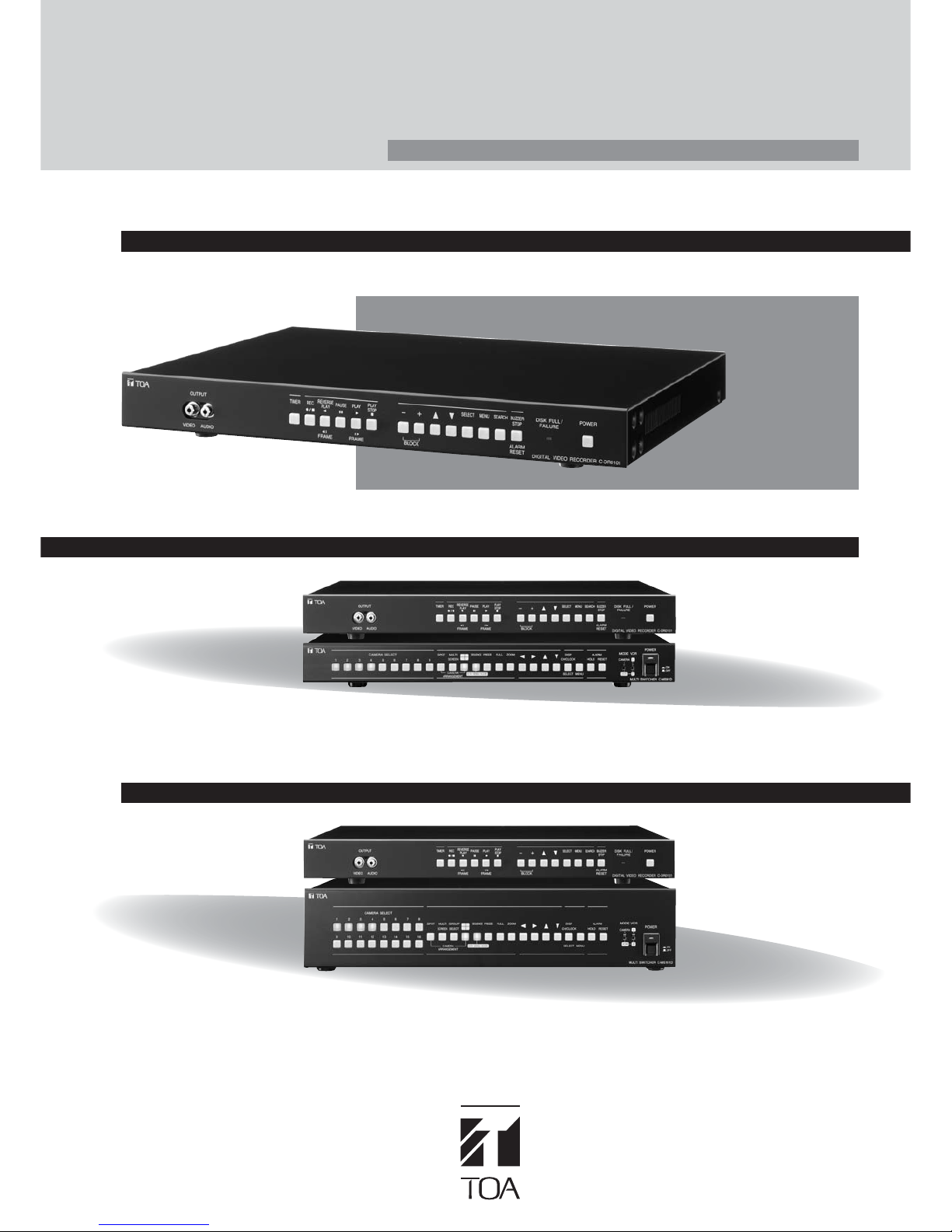
Basic Single-Channel Digital Video Recorder
9-Channel Digital Video Recording System
16-Channel Digital Video Recording System
Single-Channel Digital Video Recorders and Multiplexers
C-DR0105
(HDD 500GB)
C-DR0101
(HDD 240GB)
C-DR0100
(HDD 120GB)
Page 2
C-DR0105/C-DR0101/C-DR0100
SINGLE-CHANNEL DIGITAL VIDEO RECORDER FUNCTIONS
■
Pre- and Post-Alarm recording
Since the C-DR0101/C-DR0100/C-DR0105 are all digital units, they
are able to offer advantages that analog systems cannot such as
the pre-alarm feature which allows setting a time in eight increments
from 0 second to 5 minutes. If an alarm is generated, the unit has
already been recording from the preset time period. This makes
sure nothing is missed when viewing footage from the alarm. A
post-alarm function with similar time increments is also provided.
The C-DR0100 incorporates a 120GB HDD while the
C-DR0101 is equipped with 240GB (2 X 120GB) HDDs
and C-DR0105 is equipped with 500GB (2 X 250GB)
HDDs. Large capacity hard disk drives such as these
make it easy to achieve extended recording times for
effective monitoring.The use of large hard disk drives
eliminates having to change tapes and perform periodical
maintenance as such tasks are essential when using
conventional time-lapse VCRs. In addition, only digital
recording can offer such high picture quality, extended
recording periods and effective high-speed searching.In
order to achieve the most extended recording times while
maintaining picture and audio quality for recording and
playback, digital compression is utilized. Motion JPEG
compression is employed for pictures of 720 x 240 pixel
resolution.
Recording Priorities
High
Lower-priority recording stops whenever higher-priority recording is
commenced.
Note
Internal Timer recording does not operate even if the Timer key is pressed during
General or Alarm recording.
Low
General
Recoding
Alarm
Recoding
Internal Timer
Recording
Recording End
Timer Key pressed
Alarm Input
Alarm Input
Alarm Input
Alarm End
Rec. key pressed
Alarm End
■
500GB storage with 2 250GB HDDs built-in
■
(C-DR0105)
An immense storage capacity of 500GB is provided in the
C-DR0105 that features two 250GB disk drives built-in. This
allows recording over many hours, raising overall system
effectiveness and significantly adding to ease of use for
monitoring applications. If less recording capacity is desired, the
C-DR0101 equipped with two 120GB disk drives built-in and the
C-DR0100 equipped with a single120GB hard drive can be used.
■
High picture quality
Advanced digital compression technology provides picture quality
with a resolution that exceeds 400 lines.
Full digital operation means picture quality with clarity that easily
surpasses S-VHS.
Since all video is recorded directly to the HDD, there is no picture
deterioration even with repeated playback.
■
Versatile recording with a choice of three
■
modes:
general recording, internal timer recording and
alarm recording.
• Picture quality from a choice of levels and recording
interval from can be set independently in each mode.
• Picture quality can be selected from 5 different file sizes
ranging from a standard picture quality file size of 16KB to
a high picture quality file size of 64KB.
• Internal timer recording allows setting up to 10 different
timer programs.
• Alarm recording offers two different alarm input modes,
each allowing different items to be set to suit different
monitoring requirements.
Alarm Input
Recording Status
Alarm Output
ON
Recording
When an alarm output duration
is set to 1 second:
1 Sec
Pre-alarm Period
Alarm Recording Period
Alarm Input
Recording Status
Alarm Output
ON
Recording
Pre-alarm Period
When an alarm output is provided during alarm recording:
Recording Period
Alarm Input Mode
The Alarm Input mode for alarm recording can be set to “Edge” or “Level.”
Each input mode operates as follows:
Note
Pre-alarm recording is operated by the Alarm recording setting. It does not operate even
if an alarm is activated during General recording or Internal Timer Recording since they are
operated by their own settings.
Recording period when input mode is set to “Edge”
Recording period when input mode is set to “Level”
Post-alarm Period
Recording Functions
File Size and Picture Quality
Setting value Angle of view File size Picture quality
LEVEL 1 720 × 240 64KB
S-VHS or much greater
LEVEL 2 720 × 240 40KB S-VHS or greater
LEVEL 3 720 × 240 32KB S-VHS
LEVEL 4 720 × 240 24KB VHS
LEVEL 5 720 × 240 16KB VHS-like
Picture quality
High
Low
Page 3

■
Comprehensive high-speed search functions
Because the hard disks can store a significant amount of
recorded data, it is important that sophisticated search
functions provided:
Time Search
Inputting the date and time desired activates searching by
date/time. Once a value is input, the frame starting at the
time selected will be displayed. This makes it easy to search
forward and backward from that point.
Block Search
Selecting a block* of dates/times performs searching by
block. Once a block is selected, it will playback repeatedly.
Time Shift Search
Increasing or decreasing the amounts of time as desired
from a designated time activates searching by time shift.
The frame at the designated time will be displayed,
facilitating searching.
DATE / TIME SEARCH
JAN / 01 / 03 10 : 00
BLOCK SEARCH
[N JAN / 01 / 03 10 : 15 : 25]
[N JAN / 01 / 03 11 : 35 : 21]
[N JAN / 01 / 03 13 : 15 : 24]
[]
[––––– / –– / –– –– : –– : ––
––––– / –– / –– –– : –– : ––
]
[––––– / –– / –– –– : –– : ––]
[––––– / –– / –– –– : –– : ––]
[––––– / –– / –– –– : –– : ––]
[––––– / –– / –– –– : –– : ––]
[––––– / –– / –– –– : –– : ––]
[––––– / –– / –– –– : –– : ––]
[––––– / –– / –– –– : –– : ––]
[––––– / –– / –– –– : –– : ––]
[––––– / –– / –– –– : –– : ––]
WED JAN / 01 / 03
11 : 38 : 28
SHIFT TIME CHANGE : / KEY
SHIFTING : – / + KEY
CANCEL : SEARCH KEY
PAUSE CHANGE TIME: 10MIN
LEVEL3 1/60 A
N JAN/01/03 10:15:25 N JAN/01/03 11:35:21 N JAN/01/03 13:15:24
11:35:21 – 12:21:45
13:15:24 – 13:59:31
10:15:25 – 11:15:20
BLOCK* BLOCK* BLOCK*
■
Time Lapse recording
The C-DR0105/C-DR0101/C-DR0100 digital recorders offer
versatile time-lapse recording with recording intervals that
can be set in 15 different steps from 1/60th second to 60
seconds.
■
Audio recording
Audio recording during video recording can be enabled or
disabled as required. An audio output terminal is provided
on the rear panel for dubbing recorded audio signals.
■
Mirroring enhances reliability
■
(C-DR0105/C-DR0101)
The C-DR0105/C-DR0101 includes two hard disk drives that can
be used to record simultaneously, significantly increasing
reliability and preserving important data. Even if one HDD should
fail, the other will continue to record and playback.
■
Flexible playback modes enhance system
■
operation
•Forward and reverse playback modes
•Fast forward and fast reverse playback modes with
selectable X2, X4 and X8 speeds
•Forward Frame Playback and Reverse Frame Playback
•Forward Block and Reverse Block Playback
■
Convenient simultaneous recording and
■
playback
While the C-DR0105/C-DR0101/C-DR0100 are recording, they are
also capable of playing back recorded images without any
interruption to the recording process.
* Recorded data from start to
end of each recording constitutes
a single recorded block.
Playback Functions
Page 4
C-DR0105/C-DR0101/C-DR0100
■
Network connectability
A 100 BASE-TX ethernet port is built-in to make it easy to
distribute recorded images via LAN and WAN systems such
as the Internet.
*requires dedicated software
■
Logging
Logging options for general recording, alarm recording and
failure are provided.
■
Useful status indication
When an alarm is activated, a buzzer will sound for notification.
It can be muted if desired. A built-in indicator will provide
notification for various conditions such as HDD almost full with
less than an hour of recording remaining, recorder malfunctioning
including hard disk failure, cooling fan failure and video loss.
■
Summer Time (Daylight Savings Time)
The timer function can be adjusted for daylight savings time and
can also be adjusted to automatically switch times as well. When
a TOA digital recorder is used together with a TOA multiplexer,
there is no need to adjust both units, as the adjusted unit will
synchronize with the other unadjusted TOA unit.
■
Key-lock function
A useful key lock can be activated to prevent unauthorized access
to unit controls and keeps the digital recorder tamper-proof.
■
Compact single rackmount (1U) size
Each of the 1-channel digital recorder models feature a spacesaving 1U size to facilitate installation while incorporating
multiple useful features.
SINGLE-CHANNEL DIGITAL VIDEO RECORDER
1/60
1/30
1/15
1/10
1/5
1/3
1/2
1
2
3
5
10
20
30
60
1/60
1/30
1/15
1/10
1/5
1/3
1/2
1
2
3
5
10
20
30
60
64
C-DR0100 (120GB) C-DR0101 (240GB)
Level 1 Level 2 Level 3 Level 4 Level 5 Level 1 Level 2 Level 3 Level 4 Level 5 Level 1 Level 2 Level 3 Level 4 Level 5
C-DR0105 (500GB)
Disk Mode: Extended
Picture
quality
Recording
Intervals (sec)
Audio Recording: ONAudio Recording: OFF
Note: Recording time is given as a guideline reference.
Recording Time Table
unit: hours
8
17
33
50
97
158
227
409
681
878
1,134
1,460
1,704
1,803
1,916
9
17
34
51
103
171
257
513
1,026
1,539
2,565
5,131
10,262
15,392
30,785
13
26
52
78
150
239
337
580
901
1,112
1,356
1,631
1,815
1,884
1,961
14
27
54
81
163
271
407
813
1,627
2,440
4,067
8,134
16,268
24,403
48,805
17
33
64
95
183
289
402
674
1,011
1,220
1,450
1,697
1,855
1,913
1,976
17
34
67
101
202
337
505
1,011
2,021
3,032
5,053
10,106
20,212
30,318
60,637
22
43
84
124
234
364
498
804
1,150
1,352
1,558
1,769
1,898
1,943
1,992
22
44
89
133
267
445
667
1,334
2,668
4,002
6,670
13,340
26,680
40,020
80,041
32
62
120
176
325
494
654
996
1,334
1,516
1,684
1,848
1,942
1,973
2,008
33
65
131
196
392
654
981
1,962
3,924
5,885
9,809
19,618
39,236
58,853
117,707
17
34
67
100
195
315
454
818
1,361
1,755
2,269
2,919
3,407
3,605
3,832
17
34
68
103
205
342
513
1,026
2,052
3,078
5,131
10,262
20,523
30,785
61,570
27
53
105
155
300
478
674
1,160
1,803
2,223
2,711
3,262
3,630
3,768
3,922
27
54
108
163
325
542
813
1,627
3,254
4,881
8,134
16,268
32,537
48,805
97,610
33
65
129
191
365
577
804
1,347
2,021
2,440
2,900
3,394
3,711
3,826
3,953
34
67
135
202
404
674
1,011
2,021
4,042
6,064
10,106
20,212
40,425
60,637
121,274
44
86
168
247
468
729
996
1,607
2,300
2,704
3,117
3,538
3,795
3,885
3,984
44
89
178
267
534
889
1,334
2,668
5,336
8,004
13,340
26,680
53,360
80,041
160,081
124
240
351
651
988
1,308
1,991
2,668
3,032
3,369
3,695
3,884
3,947
4,016
65
131
262
392
785
1,308
1,962
3,924
7,847
11,771
19,618
39,236
78,471
117,707
235,413
34
68
136
203
397
643
926
1,670
2,779
3,583
4,631
5,959
6,956
7,360
7,822
34
69
139
209
419
698
1,047
2,095
4,190
6,285
10,475
20,950
41,900
62,850
125,701
54
108
213
316
612
976
1,375
2,368
3,680
4,539
5,535
6,658
7,410
7,693
8,006
55
110
221
332
664
1,107
1,660
3,321
6,642
9,964
16,606
33,213
66,427
99,641
199,282
67
133
263
389
746
1,179
1,640
2,751
4,126
4,982
5,920
6,930
7,575
7,811
8,069
68
137
275
412
825
1,375
2,063
4,126
8,253
12,379
20,632
41,265
82,531
123,796
247,593
89
174
342
504
955
1,488
2,032
3,281
4,695
5,520
6,363
7,224
7,748
7,932
8,133
90
181
363
544
1,089
1,815
2,723
5,447
10,894
16,341
27,235
55,470
108,941
163,411
326,123
129
252
490
716
1,328
2,017
2,670
4,064
5,447
6,189
6,877
7,544
7,928
8,057
8,199
133
267
534
801
1,602
2,670
4,005
8,010
16,020
24,031
40,051
80,103
160,207
240,311
480,622
Other Functions
Page 5

SETTING GUIDE
C-DR0105/C-DR0101/C-DR0100
SETTING GUIDE
The menu screens are comprised of the following setting item screens.
MAIN MENU
•
PLAY SETTING
CLOCK SETTING
DISK SETTING
REC SETTING
ON–SCREEN DISP SETTING
KEY LOCK
COMMUNICATION SETTING
LOG DISPLAY
SYSTEM MAINTENANCE
Playback Settings Screen Display Settings
Key Lock
Log Display
Main Menu Item
Menu Item
Setting Item
*
*
Playback Mode
Simultaneous Recording/Playback
Disk Settings
Recording Settings
*Disk Mode
Recording Mode
Clock Settings
Year/Month/Day
Time Synchronization
Synchronization Time
Summer Time
Picture Quality
Audio
Recording Intervals
Switcher Control Period
Disk Selection
Recoding Start Date
Preset Time
Picture Quality
Audio
Recording Intervals
Recording Pattern
Motion Detection Pattern
General Recording Settings
Internal Timer Recording Settings
Timer Setting List
Timer Setting 01–10
General/Timer Recording Log
Alarm Recording Log
System Maintenance
Menu Default Settings
Disk Formatting
Failure Log
Alarm Settings
Alarm Input Modes
Pre-Alarm Recording Periods
Alarm Recording Periods
Post-Alarm Recording Periods
Picture Quality
Audio
Recording Intervals
Buzzer Sound
Alarm Output Time
Alarm Recording Settings
Picture Quality Indication
Audio ON/OFF Indication
Recording Mode Indication
Recording Indication
Playback Indication
Remaining Time Indication
Date Indication
Time Indication
Date/Time Display Position
Disk Mode Indication
Communication Settings
RS232C Baud Rate
RS232C Flow Control
Network Settings
IP Address
Subnet Mask
Default Gateway
Switcher Synchronization
* This setting item is only applicable to the C-DR0105/C-DR0101
Recorders, and not displayed on the screen when the C-DR0100
Recorder is used.
Page 6

NOMENCLATURE
C-DR0105/C-DR0101/C-DR0100
Front Panel
Rear Panel
Timer Key
[
+
] and [–] Set Keys
Block Shift Key
Select Key
Menu Key
Up [ ] and Down [ ] Shift Keys
Playback Stop [ ] Key
Playback [ ] Key
Frame Advance [ ] Key
Recording [ / ] Key
Pause [ ] Key
Search Key
Buzzer Stop Key
Alarm Reset Key
Disk Full/Failure Indicator
Video Output Terminal
Audio Output Terminal
AC Inlet Main Power Switch RS-232C Terminal
Audio Input Terminal
Video Input Terminal
Video Output Terminal
Switcher Video Input Terminal
100BASE-TX Terminal
Power Switch
Switcher Image Output Terminal
Audio Output Terminal
Alarm Reset Output Terminal
Alarm Input Terminal
Ground Terminal
Switcher Control Output Terminal
Control Input/Output Terminal
Alarm Reset Input Terminal
Recording Start Input Terminal
Recording Stop Input Terminal
Time Sync Input/Output Terminals
Alarm Output Terminal
System Failure Output Terminal
Disk Full Output Terminal
Reverse Playback [ ] Key
Frame Reverse [ ] Key
Page 7

C-DR0105/C-DR0101/C-DR0100
SPECIFICATIONS/APPEARANCE AND DIMENSIONAL DIAGRAMS
APPEARANCE AND DIMENSIONAL DIAGRAMS (C-DR0105/C-DR0101/C-DR0100)
331
320
482
31.8
44
53.8
465
420
Unit: mm
SPECIFICATIONS
Model No.
C-DR0105
(NTSC)
C-DR0101
(NTSC)
C-DR0100
(NTSC)
1 Channel Digital Video Recorder 1 Channel Digital Video Recorder 1 Channel Digital Video Recorder
Power Source 110 – 120V AC, 50/60Hz
Power Consumption 36W 35W 24W
Image Compression System Motion JPEG
Recording Medium E-IDE Hard Disk 500GB (250GB × 2) E-IDE Hard Disk 240GB (120GB × 2) E-IDE Hard Disk 120GB (120GB × 1)
Video Input 1 input, VBS 1.0V (p-p), 75Ω, BNC
Video Output Front: 1 output, VBS 1.0V (p-p), 75Ω, RCA pin jack/Rear: 1 output, VBS 1.0V (p-p), 75Ω, BNC
Switcher Video Input 1 input, VBS 1.0V (p-p), 75Ω, BNC
Switcher Video output 1 output, VBS 1.0V (p-p), 75Ω, BNC
Audio Recording System 8 bits, Linear PCM, sampling frequency: 16kHz
Audio Input 1 input, -10dB*
1
, 10kΩ, RCA pin jack
Audio Output Front: 1 output, -10dB*
1
, 600Ω, RCA pin jack Rear: 1 output, -10dB*1, 600Ω, RCA pin jack
Frequency Response 300 – 6,000Hz
Alarm Input 1 input (EDGE, LEVEL), no-voltage make contact input, open voltage: 2V DC,
short-circuit current: 0.5mA, loop resistance: under 100Ω, screwless connector
Alarm Output 1 output, open collector output, withstand voltage: 30V DC, control current: 20mA, screwless connector
Picture Quality Changeable in 5 steps
File size: 64kB (LEVEL 1), 40kB (LEVEL 2), 32kB (LEVEL 3), 24kB (LEVEL 4), 16kB (LEVEL 5)
Pixels 720 × 240 (fixed)
Recording Intervals 15 steps (1/60, 1/30, 1/15, 1/10, 1/5, 1/3, 1/2, 1, 2, 3, 5, 10, 20, 30, 60 sec)
Pre-Alarm Recording 0 sec, 10 sec, 15 sec, 20 sec, 30 sec, 1 min, 2 min, 5 min
Alarm Recording 10 sec, 15 sec, 20 sec, 30 sec, 1 min, 2 min, 3 min, 4 min, 5 min, 10 min (Edge mode)
Post Alarm Recording 0 sec, 10 sec, 15 sec, 20 sec, 30 sec, 1 min, 2 min, 5 min (Level mode)
Date/Time Year/month/date/hour/minute/sec, 24-hours format display
Monthly deviation of within ±30 seconds (25°C)
Can be operated until the leap year 2099
Summertime (daylight saving t time) setting
Internal Timer Recording 10 independent programs (date, daily, weekly, designated day-of-the-week)
Recording interval, start and end times, picture quality, and audio on-off can be set.
Search Function Date/Time search, block search, time shift search
System Failure Output 1 output (HDD failure, Video loss, Fan failure) open collector output,
Withstand voltage: 30V DC, control current: 20mA, screwless connector
Control Input Terminal Alarm reset, Recording start, Recording stop, Clock synchronization
No-voltage make contact input, open voltage: 2V DC, short-circuit current: 0.5mA
Loop resistance: under 100Ω, screwless connector
Control Output Terminal Alarm reset, Clock synchronization, Disk full: Open collector output, withstand voltage: 30V DC,
Control current: 20mA, screwless connector
Switcher control: TTL level negative logic pulse, pulse width over 17ms, Screwless connector
Communication Function RS-232C (External control function)*
2
, D-sub connector (9 P, male)
100BASE-TX Ethernet terminal
Memory Backup 720 hours (full charge), clock date retention
Operating Temperature +5˚C to +40˚C
Operating Humidity Under 80% RH (no dew condensation)
Finish Panel: Aluminum extrusion, black, 30% gloss Case: Surface-treated steel plate, black, 30% gloss
Dimensions 420 (W) × 53.8 (H) × 331 (D) mm
Weight 5.3kg 5.3kg 4.5kg
Accessory Power supply cord (2m) × 1
Option Rack mounting bracket: MB-15B
*
1
0dB = 1V
*
2
Control software is not supplied as standard.
Page 8

DIGITAL VIDEO RECORDERS & MULTIPLEXERS
DIGITAL VIDEO RECORDING
Multi-Channel Digital Video Recording System
Cost-effective and high-performance digital video recorder
systems to meet a user's specific requirements can be
assembled. A maximum 16 channel recording system can be
flexibly configured by combining a C-DR0105/C-DR0101/
C-DR0100 single-channel recorder with a TOA multiplexer such
as the C-MS91D and C-MS161D model by utilizing the
RS-232C interface to link the units. Such a system comprising
TOA digital video recorders and multiplexers offer significant
system advantages such as automatic mode switching by the
multiplexer on playback and automatic time synchronization
between the digital video recorder and multiplexer.
9-Channel Digital Video Recording System
16-Channel Digital Video Recording System
Multiple Split Screen Display
Live monitoring and digital video recorder playback can be seen in all split screen options (16 segment only with C-MS161D).
In a 4-segment screen, live cameras can be selected in sequence.
With camera selection, a required camera can be assigned priority to always be shown (camera 1 selected).
1
2
3
4
5
6
7
8
9
10 11
12
13 14
15
16
16 -segment
1
1
2
2
3
4
5
6
7
8
10-segment
1
2
3
4
5
6
7
8
9
9-segment
1
1- segment
1
2
3
4-segment
4
(only when real time monitoring)
For live camera monitoring segments, cameras can be assigned to the desired position.
By using shift up/down and shift left/right
function keys, the user can select the
desired multi-segment screen.
Then the 1-16 camera keys can be used
to assign cameras to the segments in
the multi-segment screen selected
earlier.
3
4
5
6
7
8
9
1
2
10
3
4
5
6
71
8
9
10
2
Group1
2
3
4
1
Group 2
5
6
7
8
9
10
11
12
Group 3
13
14
15
16
Group 4
Group1
2
3
4
1
Group 2
1
5
6
7
1
8
9
10
Group 3
1
11
12
13
Group 4
Page 9

SYSTEM
• 2x Zoom (adjustable zoom position)
• The auto-panning and -tilt
functions electronically simulate
eye-movement of a sentry
Electronic Zoom, Auto Tilt and Auto Panning
Features Included.
TOA multiplexers enable electronic 2X zooming to be
selected along with desired position. In addition, electronic
Auto Pan and Auto Tilt functions enhance monitoring
and surveillance capability.
Motion Detection Mode
TOA's new multiplexers incorporate an extremely useful
function of smart image detection. The object size and
detection areas can be set for each camera individually.
Object Size Settings
The full screen is divided into 192
frames (16 horizontal x 12 vertical)
which do not appear on the screen.
Size of the object for detected can be
set by selecting horizontal and vertical
frames and inputting these values.
Motion Detection Area setting
The full screen is divided into 16 areas (4 horizontal x 4 vertical) and
motion detection can be set to activate in any of the 16 areas.
For example, when wishing to eliminate constantly moving portions
such as trees swayed
by wind from the
motion detection area,
set the corresponding
area to OFF(- -).
Sensitivity Setting
To minimize detection errors, five levels of sensitivity settings are
provided to allow fine adjustment control.
The multiplexer detect the change of brightness in the area that is
larger than the set object size in the activated areas.
Alarm Recording
The number of recording frames for the camera that detected motion
can be set to increase.
For example, when wishing to detect a
person but not wishing to detect a dog,
set the object size to be larger than the
dog and smaller than a person. If the
object size is set for 2 horizontal x 5
vertical frames, such as in the figure at
right, a person's motion can be
detected, but motion of the dog will
not be detected.
1 area
1 frame
Increase the number of recording frames for camera 3
123456789
10 11 12 13 14
CAMERA
CAMERA
CAMERA
CAMERA
CAMERA
CAMERA
CAMERA
CAMERA
CAMERA
CAMERA
CAMERA
CAMERA
CAMERA
CAMERA
13234353637383
CAMERA
CAMERA
CAMERA
CAMERA
CAMERA
CAMERA
CAMERA
CAMERA
CAMERA
CAMERA
CAMERA
CAMERA
CAMERA
CAMERA
Display Configuration Table
Live DVR Playback
C-MS161D C-MS91D C-MS161D C-MS91D
Sequence √√ ––
Split(4)-screen sequence √√ ––
Full-Screen display √√ √ √
Split(4)-screen display √* √* √√
Split(9)-screen display √* √* √√
Split(10)-screen display √* √*––
Split(16)-screen display √*– √ –
Zoom display (2x) √√ √ √
Auto-panning and tilt display
√√ √ √
Freeze √√ √ √
* Robotic motion
Motion Detection Operation
When Camera 3 detected motion
Detection size: 2 horizontal x 5 vertical frame
ON
ON
ON
ON
ON
ON
ON
ON
ON
ON
ON
ON
ON
ON
ON
ON
ON
ON
ON
ON
ON
ON
ON
ON
ON
ON
Maximum 1,000GB recording time possible.
To gain the very maximum recording time possible, two TOA
C-DR0105 digital video recorders can be set up for serial
recording in conjunction with a TOA multiplexer. Connected
in this manner, a digital recorder will signal the second digital
video recorder when its hard disk drive is full, automatically
starting the second recorder so nothing will be missed.
.
Multiplexer
When first digital video recorder storage is full, the second unit will
start to record.
When the second digital recorder storage is full, recording starts again
on the first unit by recording over what was previously recorded.
DVR 1 DVR 2
DVR 1
DVR 2
250GB HDD 250GB HDD 250GB HDD 250GB HDD
250GB HDD 250GB HDD 250GB HDD 250GB HDD
Multiplexer
Page 10

DIGITAL VIDEO RECORDERS & MULTIPLEXERS
DIGITAL VIDEO RECORDING
Versatile Alarm Functions
TOA multiplexers offer many alarm functions that are easily
set in the setup menu.
Sensor Alarm: Each camera connected is equipped with a
sensor input terminal. Alarm activation triggers a buzzer while
onscreen display warning and video recording speed is
automatically set to standard speed. Multiple Alarm Inputs allow
prioritizing cameras when an alarm is generated. When multiple
alarms are generated, video image switching is suspended and
the alarms are put on hold so that the operator can select the
alarm’s corresponding camera’s images to view in desired
order. In addition, each alarm terminal can be set to notify on a
break-or-make or make basis.
Digital Video Recorder Reproduction Alarm: A buzzer
sounds when playing back the part of a recording that contains a
sensor alarm event.
Video Loss Alarm: Alerts when power or signal from a
particular camera is lost. Letters "VL" and the camera
ID number will be displayed.
Alarm Information: Dates, times and camera ID number of
sensor and video loss alarms can be reviewed on an
independent alarm information screen. A maximum of 64
events will be recorded and a new event will record over the
oldest event.
Multi-Language Ability
Offering flexible use for multi-language environments, TOA
multiplexers will show onscreen information and allow menudriven set-up and operation in English, French, and Spanish.
Summer Time (daylight savings)
The timer function can be adjusted for summer time and can
also be set to adjust automatically for it.
Key-lock function
A key-lock function can be set to prevent unauthorized access
to unit controls and tampering.
Remote control
Each multiplexer is equipped with an RS-232C port on the
rear panel so that it can be linked for control externally from a
remote location. The C-RM500 Remote Controller can be
used to switch and select cameras individually or by group,
sequence-display, multi-split screen modes. It connects to the
multiplexer via the remote control terminal on the rear panel.
Mechanism of a Multiplexer
CAMERA1
CAMERA 2
Frame Recording Function
The frame recording system switches cameras for each frame
while recording. For every frame, a multiplexer sends a
different picture taken by a different camera to a Digital Video
Recorder so that a single Digital Video Recorder is able to
make recordings for multiple cameras.
Continuous images can be reproduced during replay by
reading corresponding frames for each camera. Recorded
images may be viewed as full-screen display for each
independent camera or in a split-screen display that shows
multiple camera views at the same time. A conventional
sequential switcher changes camera feeds every few
seconds,making continuous motion replay impossible.
Allocating a Digital Video Recorder for each camera is also
prohibitive in terms of costs. Multiplexers that use the
frame recording system records images from all cameras
and are cost-effective.
Page 11

SYSTEM
Power source 110 – 120V AC, 50/60Hz
Power consumption 18W
Video Input Camera input 16 channels, VBS 1.0V(p-p) 75Ω, BNC, 2:1 interlace*
2
9 channels, VBS 1.0V(p-p) 75Ω, BNC, 2:1 interlace*
2
VCR input 2 channels, VBS 1.0V(p-p) 75Ω, BNC
Video output Camera output 16 channels, VBS 1.0V(p-p) 75Ω, BNC, loop-through output 9 channels, VBS 1.0V(p-p) 75Ω, BNC, loop-through output
Monitor output 2 channels (Either channel can be set as spot output.),
VBS 1.0V(p-p) 75Ω, BNC
VCR output 2 channels, VBS 1.0V(p-p) 75Ω, BNC
Alarm Alarm Input
16 channels, no-voltage make contact input, open voltage: 5V DC 9 channels, no-voltage make contact input, open voltage: 5V DC
,
short-circuit current: 5mA, D-sub connector (25 P) short-circuit current: 5mA, D-sub connector (25 P)
make/break is selectable by menu setting make/break is selectable by menu setting
Alarm output 1 channel, NPN open collector output, withstand voltage: 20V DC,
control current: under 20mA, D-sub connector (25 P)
Video loss alarm output 1 channel, NPN open collector output, withstand voltage: 20V DC,
control current: under 20mA, D-sub connector (25 P)
Alarm hold output 1 channel, NPN open collector output, withstand voltage: 20V DC,
control current: under 20mA, D-sub connector (25 P)
Alarm cancel output 1 channel, NPN open collector output, withstand voltage: 20V DC,
control current: under 20mA, D-sub connector (25 P)
Motion detection output 1 channel, NPN open collector output, withstand voltage: 20V DC,
control current: under 20mA, D-sub connector (25 P)
Alarm time MANUAL, 10s, 15s, 20s, 30s,
1 – 5min (adjustable in 1-minute steps), Infinite
Buzzer ON or OFF (selectable)
Remote Remote input 12 channels (6 channels: binary input), no-voltage make
contact input, open voltage: 5V DC, short-circuit current: 5mA,
D-sub connector (25 P)
Remote output: 10 channels (6 channels: binary output) NPN open collector
output, withstand voltage: 20V DC, control current: under 20mA,
D-sub connector (25 P)
Other Function Motion detection, Selection of the motion detection pattern, Key lock,
Automatic recognition on time-lapse recording,
Selection of the recording pattern,
Selection of the language (English/Spanish/French) on the menu screen
VCR Control Switcher control input 2 channels, no-voltage make contact input,
open voltage: 5V DC, short-circuit current: under 0.3mA, Screwless connector
Alarm output 2 channels, NPN open collector output, withstand voltage: 20V DC,
control current: under 20mA, Screwless connector
Alarm cancel output 2 channels, NPN open collector output, withstand voltage: 20V DC,
control current: under 20mA, Screwless connector
Audio VCR input: 2 channels, –10dB*
1
, over 50kΩ, RCA pin jack
Monitor output 1 channel, –10dB*
1
, low impedance, RCA pin jack
External control RS-232C 1 channel, D-sub connector (9 P, male)
Remote control terminal 1 each of input and output, screwless connector
Dedicated Remote Controller Controlled by dedicated remote controller C-RM100 (option),
C-RM500 (option)
Recording Output At least 1 frame intervals
Screen display [Camera screen]
Full screen selection Selection of the desired camera
Multiple-split screen 4-, 9-, 10- and 16-segment screen (all intermittent displaying, 4- and 9-segment screen (all intermittent displaying,
changeable positioning on the segment screen.) changeable positioning on the segment screen.)
Zoom Electronic 2x zoom for the desired camera
(zooming position changeable, auto tilt, panning possible)
Freeze Freeze screen for individual cameras
Automatic sequence Full screen (individual cameras), 4-segment screen (camera groups),
switching time intervals of 0 – 99 sec. that can be set in 1 sec. units.
[VCR reproduction screen]
Full screen selection Selection of the desired camera
Multiple-split screen 4-, 9-, and 16-segment screen 4- and 9-segment screen
Zoom Electronic 2x zoom for the desired camera
(zooming position changeable, auto tilt, panning possible)
Freeze Freeze screen for individual cameras
[Spot screen]
Full screen selection Selection of the desired camera
Automatic sequence Full screen (individual cameras),
switching time intervals of 0 – 99 sec. that can be set in 1 sec. units.
Indication Camera title Up to 8 characters (alphanumeric and symbols)
camera No. and time/date can be displayed.
Number of Effective Pixels 720 × 464 pixels
Operating Temperature 0˚ to +40˚C
Finish Panel: aluminum extrusion, black, 30% gloss
Case: Surface-treated steel plate, black, 30% gloss, paint
Dimensions 420 (W) × 96.6 (H) × 333.9 (D) mm 420 (W) × 51.8 (H) × 334.1 (D) mm
Weight 4.3kg 3.5kg
Accessory Power cord (2m) × 1
Option Rack mounting bracket: MB-23B
*
1
0dB = 1V
*2 That line-locked cameras cannot be connected to the C-MS161D and C-MS91D.
C-MS161D (NTSC) C-MS91D (NTSC)
SPECIFICATIONS
Page 12

Accessory
YR-S2320
RS-232C cross cable
Specifications are subject to change without notice.
Printed in Japan (0503) 833-53-017-6A u
TOA Corporation
URL : http://www.toa.jp/
1-Channel System Example
C-DR0105/C-DR0101/C-DR0100
Camera
max. 9
9-Channel System Example
C-MS91D
C-DR0105/C-DR0101/C-DR0100
Camera
max. 16
16-Channel System Example
C-MS161D
C-DR0105/C-DR0101/C-DR0100
Camera
max. 16
16-Channel System Example (Series Recording 1,000GB HDD)
C-MS161D
C-DR0105
C-DR0105
Camera
Switcher Control
Alarm
RS-232C
(YR-S2320)
Video IN/OUT
Video OUT/IN
Switcher Control
RS-232C
(YR-S2320)
Video IN/OUT
Video OUT/IN
Switcher Control
RS-232C
(YR-S2320)
Video IN/OUT
Video OUT/IN
Switcher Control
Adjusting Time Control
Disk Full
Recording Start
Video IN/OUT
Video OUT/IN
Monitor
Monitor
Monitor
Monitor
Alarm
Alarm
Alarm
SYSTEM EXAMPLES
 Loading...