

Page 1
Thank you for purchasing TOA’s Outdoor camera housing. Please carefully follow the instructions in this
manual in order to ensure long, trouble-free use of your camera housing.
OUTDOOR CAMERA
HOUSING
C-CH200
C-CH200FH
C-CH210FH
INSTRUCTION MANUAL
C-CH210FH
Page 2

2
TABLE OF CONTENTS
1. SAFETY PRECAUTIONS ................................................................................ 3
2. GENERAL DESCRIPTION ............................................................................. 5
3. HANDLING PRECAUTIONS .......................................................................... 5
4. NOMENCLATURE ............................................................................................. 6
5. INSTALLATION
5.1. Installation Examples
5.1.1. When using the C-BC200H Housing Fixing Stand ................................. 7
5.1.2. When using the C-PH200 Outdoor Pan/Tilt Head .................................. 7
6. CABLE ROUTING ............................................................................................. 8
7. CABLE WIRING
7.1. External Control Cable and Housing Terminal Block Wiring ............................. 9
7.2. Zoom Lens Wiring ............................................................................................ 10
7.3. Camera Wiring
7.3.1. 24 VAC Camera ..................................................................................... 10
7.3.2. Coaxial Single-cable Camera ................................................................ 10
7.4. Coaxial Cable End Processing ........................................................................ 11
8. CONNECTION EXAMPLES
8.1. Connections to the CC-5011B Direct Control System Remote Controller
8.1.1. When connecting the C-CH210FH directly to the CC-5011B ................ 12
8.1.2. When using the C-PH200 Outdoor Pan/tilt Head ................................... 13
8.2. Connections to the CC-5120 Relay Box
8.2.1. When connecting the C-CH210FH directly to the CC-5120 ................... 14
8.2.2. When using the C-PH200 Outdoor Pan/tilt Head ................................... 15
8.3. Connections to the C-RB100 Coaxial Multiplex Control Relay Box
8.3.1. When connecting the C-CH210FH directly to the C-RB100 .................. 16
8.3.2. When using the C-PH200 Outdoor Pan/tilt Head ................................... 17
9. CAMERA AND ZOOM LENS INSTALLATION ........................................ 18
10. WIPER BLADE REPLACEMENT (C-CH210FH only)........................... 19
11. SPECIFICATIONS ............................................................................................ 20
Accessories .............................................................................................................20
Page 3

3
1. SAFETY PRECAUTIONS
• Be sure to read the instructions in this manual section carefully before use.
• Make sure to observe the instructions in this section as the conventions of safety symbols and messages
regarded as very important are included.
• Please keep this instruction manual handy for future reference.
Safety Symbol and Message Conventions
Safety symbols and messages described below are used in this manual to prevent bodily injury and property
damage which could result from mishandling. Before operating your equipment, read this manual first so you
are thoroughly aware of the potential safety hazards as well as understand the safety symbols and messages.
Indicates a potentially hazardous situation which could result in death
or serious personal injury if ignored or mishandled.
WARNING
When Installing the Camera Housing
• Use the unit only with the voltage specified on the unit. Using a voltage higher than that which is specified
may result in fire or electric shock.
• To prevent lighting strikes, install the unit at least five meters away from a lightning rod, and yet within the
protective range (angle of 45°) of the lightning conductor. Lightning strikes may cause a fire, electric shock
or personal injury.
• Leave the installation of the unit to your TOA dealer because the installation requires expert knowledge. If an
inexperienced installer installs the unit, the unit may fall, possibly causing personal injury.
• Avoid installing the unit in vibratory locations. Mounting screws and bolts loosen, which causes the unit to fall
off, possibly resulting in personal injury.
• When installing the unit in snowy areas, take appropriate measures so that snow does not pile up on the
unit. The weight of snow causes the unit to fall off, possibly resulting in personal injury.
• Be sure to install the unit with two or more persons. If it is handled by a single person, the unit may fall or
topple over, causing personal injury.
• Install the unit only with the specified method. Failure to follow this instruction may cause extreme force to
be applied to the unit and the unit to fall, resulting in personal injury.
Page 4
4
Indicates a potentially hazardous situation which could result in death
or serious personal injury if ignored or mishandled.
WARNING
When Installing the Camera Housing
• Use nuts and bolts that are appropriate for the ceiling’s or wall’s structure and composition. Failure to do so
may cause the unit to fall, resulting in personal injury.
• Tighten each nut and bolt securely. Ensure that there are no loose joints after installation to prevent
accidents that could result in personal injury.
• Use the specified type of pan/tilt head, housing fixing stand and wall mounting bracket. If the unit is installed
in combination with equipment not specified, the unit may fall, possibly resulting in personal injury.
• Avoid installing the unit in locations exposed to sea breeze or corrosive gas. The unit’s mount may be
subject to corrosion, which could cause the unit to fall, possibly resulting in personal injury.
When Using the Camera Housing
• Should the following irregularities be found during use, immediately switch off the power, disconnect the
power supply plug from the AC outlet and contact your nearest TOA dealer. Make no further attempt to
operate the unit in this condition as this may cause a fire or electric shock.
• If you detect smoke or a strange smell coming from the unit.
• If water or other foreign objects get into the unit.
• If you drop the unit onto the floor or the unit’s case breaks.
• If the power supply cord is damaged (exposure of cable core, disconnection, etc.).
• If no picture is displayed on the monitor.
• Never open or remove the unit’s case to prevent a fire or electric shock, as there are high voltage
components inside the unit. Refer all servicing to your nearest TOA dealer.
Indicates a potentially hazardous situation which, if mishandled, could
result in moderate or minor personal injury, and/or property damage.
CAUTION
When using the Camera Housing
• Do not place heavy objects on the unit as this may cause the unit to topple over or fall down and personal
injury could result.
• Be sure to use a dedicated power supply device. Using other devices may cause a fire.
Page 5

5
Indicates a potentially hazardous situation which, if mishandled, could
result in moderate or minor personal injury, and/or property damage.
CAUTION
When using the Camera Housing
• Do not stand or sit on, nor hang down from the unit as this may cause the unit to topple over or fall down,
possibly resulting in personal injury.
• Keep cable wiring as far away as possible from the unit’s heater (C-CH200FH and C-CH210FH only). Also,
do not insert the flammable into the unit. A fire or electric shock may result.
• Do not touch the unit’s heater (C-CH200FH and C-CH210FH only) as this could lead to a burn.
• Avoid touching the sharp edge of the case as this could result in personal injury.
• Have the unit periodically checked by the dealer from where it was purchased. Should the mounting bracket
corrode or structurally deteriorate, the mounted unit could fall down, possibly resulting in personal injury.
2. GENERAL DESCRIPTION
TOA’s C-CH200, C-CH200FH, and C-CH210FH camera housings are designed to house a video camera,
single-focus lens, zoom lens and other components to protect them from the direct sunlight, wind and rain
when they are installed outdoors.
The C-CH200FH comes with a heater and a fan, while the C-CH210FH is equipped with a heater, a fan, a
defroster and a wiper.
3. HANDLING PRECAUTIONS
• To clean the case and panel, use a cloth dampened in a neutral detergent. Never use benzene, thinner,
chemically-treated towel or other volatiles, because their use may damage the unit’s finish.
• Take care not to pinch the wiper when opening and closing the case.
• The wiper blade will wear out over years of use, so be sure to replace it periodically.
• Only use the wiper as needed on rainy days, since dry operation can cause the blade to wear out quickly
and stick to the front glass.
• About General Maintenance Parts
The following parts are replaceable general maintenance parts. Their life expectancy varies depending on
the environment and conditions of their use. Replace such parts referring to the following guidelines on their
life expectancies. Please note that replacement of such maintenance parts is not covered by warranty.
• Wiper blade (C-CH210FH): Approximately 12 months
• Micro-switch (C-CH210FH): 200,000 times
• Motor for wiper (C-CH210FH): 8,000 hours
• Fan (C-CH200FH and C-CH210FH): 50,000 hours
Page 6
6
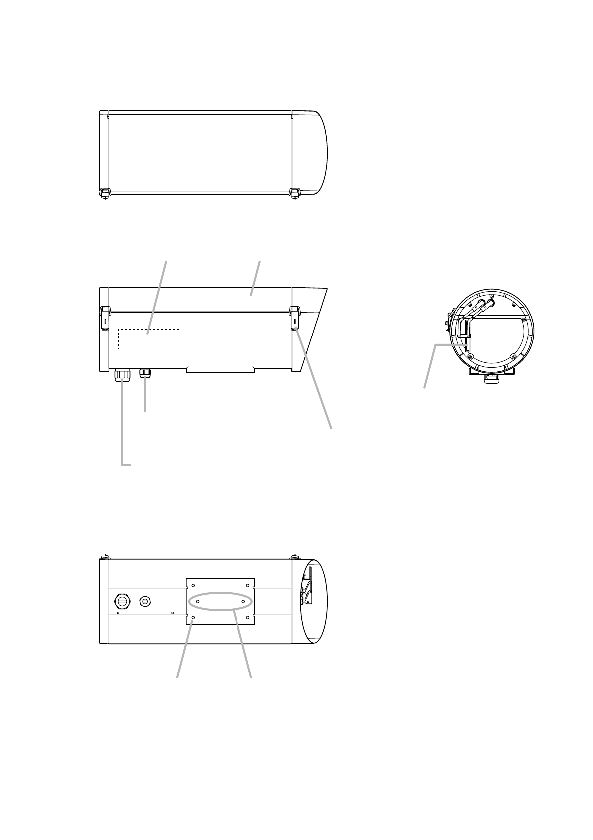
4. NOMENCLATURE
[Top view]
Junction circuit board
(inside)
[Side view]
Sunshade
[Front view]
[Bottom view]
Housing mounting hole
(for outdoor pan/tilt head)
Cable entry bushing
(Applicable cable diameter: Ø 5 – 9.5 mm)
Cable entry bushing
(Applicable cable diameter: Ø10 – 17 mm)
Housing mounting hole
(for Housing Fixing Stand)
Wiper
(C-CH210FH only)
Snap fastener
Used to open or close the sunshade.
Note: Take care not to pinch the wiper when
opening and closing the sunshade.
Page 7

7
5.1.1. When using the C-BC200H Housing Fixing
Stand:
5.1.2. When using the C-PH200 Outdoor Pan/Tilt
Head:
M6 x 12 hexagonal head bolt with washer
2 pieces (accessory)
M6 x 12 hexagonal head bolt with washer
4 pieces (accessory)
Bolts to be used for installation: Bolts to be used for installation:
5. INSTALLATION
The housing can be mounted on a wall by way of an optional mounting bracket or pan/tilt head. Use the
housing mounting holes when mounting.
5.1. Installation Examples
Outdoor Camera Housing
C-CH200
C-CH200FH
C-CH210FH
Outdoor Pan/Tilt Head
Housing Fixing Stand
C-BC200H
C-PH200
Wall Mounting Bracket C-BC200K
Camera housing
mounting hole
C-BC200H
(optional)
C-BC200K
(optional)
Camera housing
mounting hole
C-PH200
(optional)
C-BC200K
(optional)
Page 8

8
6. CABLE ROUTING
1. From the two cable entry bushings provided on the housing’s bottom surface, select the one that is
appropriate for the diameter of cable to be used (control cable or coaxial cable).
2. Remove the selected bushing’s cap, and rubber membrane attached to prevent the entries of water and
dust.
3. Run the cable through the cap to route the cable to the inside of the housing through the bushing.
4. Rotating the bushing cap, adjust the bushing diameter so that no gap is created at the cable entry area of
the bushing.
Note
• Be sure to attach the rubber packing ring after routing the cable through the bushing.
• If a gap is created at the cable entry area of the bushing, wrap the self-adhesive type butyl rubber tape
around the cable to prevent rainwater from entering.
• Check to be sure that the routed cable is securely fixed by lightly pulling it.
[Cross-sectional view of bushing]
Camera housing
Cable entry bushing
Rubber packing ring
(Attach securely)
Control cable or coaxial cable
Page 9

9
y
Terminal Block
When directly connecting to the
remote control units and relay boxes
When using the C-PH200 Outdoor
Pan/Tilt Head
No. ApplicationIndication C-CH200
C-CH200FH C-CH210FH
C-CH200
C-CH200FH C-CH210FH
1
24VAC input (common)AC COM
OO
2
24VAC inputAC HOT
OO
3
Camera power 24 VAC
CAMERA POWER
4
DefrosterDEF
5
WiperWIPER
6
Not connected (unused)NC
7
Lens commonLENS COM
8
IrisIRIS
9
FocusFOCUS
10
ZoomZOOM
11
Not connected (unused)NC
12
Video output (coaxial shield)VIDEO GND
OOO
13
Video output (coaxial core)VIDEO OUT
OOO
Connect the housing cable
supplied with the C-PH200 to
each terminal.
Note
The number of the housing
cable lead wire matches the
terminal number the lead wire
is connected to.
7. CABLE WIRING
7.1. External Control Cable and Housing Terminal Block Wiring
CAUTION
• Keep wiring as far away as possible from a heater. (CCH200FH and C-CH210FH only.) Failure to do so may
cause a fire or electric shock.
• Do not touch a heater because fingers may be burned.
(C-CH200FH and C-CH210FH only.)
• Be sure to use the optional CC-5941B 24 VAC adapter
for the 24 VAC power supply. Using adapters other than
the dedicated type could lead to a fire.
Note: Make sure that the power is switched ON after wiring completion.
The junction circuit board shown at
right is exposed if the sunshade is
opened.
Note
Do not connect the AC input to the
Video output. If connected by
mistake, the camera will fail.
Terminal block (A) is set as shown in the following
table. Perform wiring by selecting combinations of
equipment to be used.
*1It is convenient to make a connection by way of Terminal block (B) when using the 24 VA camera.
*2Connect when using a zoom lens. When using an auto-iris motorized zoom lens, terminal 8 (IRIS) is not
used.
O
O
O
*
1
O
*
1
O
*
1
O
*
1
O
*
2
O
*
2
O
*
2
O
*
2
O
*
2
O
*
2
O
*
2
O
*
2
O
*
2
O
*
2
O
*
2
O
*
2
Junction circuit board
Sunshade
Heater
CN1
1
CN3
1
CN4
CN6
1
CN5
Terminal block (B)
Goes to cameras.
CCH200チュウケイキバン
CN2
AC
COMACHOT WIPERDEF
1
1
1234567891011
1
CN7
1
CAMERAPOWER OUT
CAMERA
POWER NCZOOMFOCUSIRIS
NC
VIDEO VIDEO
GND
LENS
COM
Terminal block (A)
Goes to remote control units,
rela
boxes or outdoor pan/tilt heads.
1312
VIDEO VIDEO
OUT
GND
TB2
CN8
1
TB1
Page 10

10
7.3.2. Coaxial Single-cable Camera (when using the C-PH200 Outdoor Pan/tilt Head)
7.2. Zoom Lens Wiring
7.3. Camera Wiring
7.3.1. 24 VAC Camera
Zoom lens
Camera
Connects to the 4-pole connector (CN8)
on the junction circuit board.
Zoom lens cable for internal wiring (accessory)
Wiring Diagram
1
2
3
4
4-pole connector (female)
LENS COMMON
IRIS
FOCUS
ZOOM
4-pole connector on the circuit board
Terminal block (B)
Camera power supply cable for internal wiring
(accessory)
VIDEO VIDEO
GND OUT
DC12 V
AC24 V
Shrink tube processing side
1
VIDEO OUT
2
POWER O
Core side
CAMERA POWER OUT
Coaxial cable for internal wiring
(accessory)
Coaxial cable
Note
No coaxial cable is supplied with
the camera. Prepare it locally.
Terminal block (B)
CAMERA POWER OUT
VIDEO VIDEO
GND OUT
1312
VIDEO VIDEO
GND
1312
VIDEO VIDEO
GND
12
13
To C-PH200
video output
Shield clamp
Page 11

11
7.4. Coaxial Cable End Processing
Process the coaxial cable end as follows:
3C-2V Cable
1. Strip the cable sheath 20 mm from the cable end.
2. Bend back braided copper shields over the cable sheath, then remove
the insulating material 15 mm from the cable end.
5C-2V Cable
1. Strip the cable sheath 30 mm from the cable end, and braided copper
shields 20 mm.
2. Remove the insulating material 15 mm from the cable end.
20
155
10 20
155
Page 12

12
8. CONNECTION EXAMPLES
8.1. Connections to the CC-5011B Direct Control System Remote Controller
8.1.1. When connecting the C-CH210FH directly to the CC-5011B:
*
1
Use cables with diameter of over 1 mm when connecting the CC-5941B to the CC-5011B.
*2For how to mount the C-5011B, refer to its instruction manual.
CC-5941B 24 VAC Adapter
HOUSING
MAIN
POWER
1212
CAMERA 3
12
Note
Note correct polarity when connecting the dedicated AC adapter.
Reversed polarity connections will cause damage to equipment.
CAMERA 1
12
POWER
CAMERA 2
12
6-core cable*
FUSE 1 A
MAIN POWER
12
24 V AC
HOUSING POWER MAIN POWER ± 6 V DC
12
24 V AC
To Camera Drive Unit’s
CAMERA IN terminal
C-CH210FH
Junction circuit board terminal block (B)
CAMERA POWER
VIDEO GND
VIDEO OUT
12VIDEO GND
13VIDEO OUT
1
CC-5011B Direct Control System Remote Controller*
MAIN POWER 24 V DC HOUSING POWER 24 V AC
FOCUS ZOOM COM UP DOWN RIGHT LEFT AUTO CAMERA COM COM WIPER DEF ON
2
REMOTE CONTROL UNIT
model CC-5011B
-
ACIRIS
Junction circuit board terminal block (A)
11NC
10ZOOM
9FOCUS
8IRIS
7LENS COM
6NC
5WIPER
4DEF
CAMERA POWER
3
2AC HOT
1AC COM
Note
Take care not to connect the AC input to the video output.
If connected by mistake, the camera will fail.
Page 13

13
8.1.2. When using the C-PH200 Outdoor Pan/tilt Head:
*
1
Use cables with diameter of over 1 mm when connecting the CC-5941B to the CC-5011B.
*2For how to mount the C-PH200 and the CC-5011B, refer to their respective instruction manuals.
CC-5941B 24 VAC Adapter
HOUSING
MAIN
POWER
1212
CAMERA 3
12
Note
Note correct polarity when connecting the dedicated AC adapter.
Reversed polarity connections will cause damage to equipment.
CAMERA 1
12
POWER
CAMERA 2
12
FUSE 1 A
6-core cable*
MAIN POWER
12
24 V AC
HOUSING POWER MAIN POWER ± 6 V DC
12
24 V AC
Terminal (lower)
Terminal (upper)
C-CH210FH
Junction circuit board terminal block (B)
CAMERA POWER
1
CC-5011B Direct Control Remote Controller*
MAIN POWER 24 V DC HOUSING POWER 24 V AC
FOCUS ZOOM COM UP DOWN RIGHT LEFT AUTO CAMERA COM COM WIPER DEF ON
4 57
123
7
10
9
12
3 1
542
2
REMOTE CONTROL UNIT
model CC-5011B
-
ACIRIS
Inside of C-PH200
C-PH200 Outdoor-use
Pan/tilt Head**
VIDEO GND
VIDEO OUT
12VIDEO GND
13VIDEO OUT
Coaxial shield
Coaxial core
12
13
Junction circuit board terminal block (A)
CAMERA POWER
11NC
10ZOOM
9FOCUS
8IRIS
7LENS COM
6NC
5WIPER
4DEF
3
2AC HOT
1AC COM
Peach
White
Orange
Purple
Red
Gray
Blue
Yellow
Green
10
9
8
To VIDEO terminal
7
5
Housing cable
4
3
2
1
Note
Take care not to connect the AC input to the video output.
If connected by mistake, the camera will fail.
Page 14

14
8.2. Connections to the CC-5120 Relay Box
8.2.1. When connecting the C-CH210FH directly to the CC-5120:
* For how to mount the CC-5120, refer to its instruction manual.
CC-5111B Relay-controlled Remote Controller
TALLY CAMERA DEF WIPER AUTO LEFT RIGHT DOWN UP TELE NEARWIDE FAR OPEN CLOSECOM
CC-5120 Relay Box*
Control input terminal
OPEN FAR NEAR WIDE TELE UP DOWN RIGHT LEFT AUTO DEFWIPER CAMERATALLY COMCLOSE
IRIS FOCUS ZOOM ON-AC WIPER DEF UP DOWN RIGHT AUTOLEFT CAMERA AC-COMDC-COM
Control output terminal
To Camera Drive Unit’s
CAMERA IN terminal
C-CH210FH
Junction circuit board terminal block (B)
CAMERA POWER
VIDEO GND
VIDEO OUT
12VIDEO GND
13VIDEO OUT
Junction circuit board terminal block (A)
11NC
10ZOOM
9FOCUS
8IRIS
7LENS COM
6NC
5WIPER
4DEF
CAMERA POWER
3
2AC HOT
1AC COM
Note
Take care not to connect the AC input to the video output.
If connected by mistake, the camera will fail.
Page 15

15
y
8.2.2. When using the C-PH200 Outdoor Pan/tilt Head
* For how to mount the C-PH200 and the CC-5120, refer to their respective instruction manuals.
CC-5111B Relay-controlled Remote Controller
TALLY CAMERA DEF WIPER AUTO LEFT RIGHT DOWN UP TELE NEARWIDE FAR OPEN CLOSECOM
CC-5120 Relay Box*
Control input terminal
OPEN FAR NEAR WIDE TELE UP DOWN RIGHT LEFT AUTO DEFWIPER CAMERATALLY COMCLOSE
IRIS FOCUS ZOOM ON-AC WIPER DEF UP DOWN RIGHT AUTOLEFT CAMERA AC-COMDC-COM
Control output terminal
Terminal (lower)
Terminal (upper)
9
7
C-CH210FH
Junction circuit board terminal block (B)
CAMERA POWER
VIDEO GND
VIDEO OUT
12VIDEO GND
13VIDEO OUT
Junction circuit board terminal block (A)
11NC
10ZOOM
9FOCUS
8IRIS
7LENS COM
6NC
5WIPER
4DEF
CAMERA POWER
3
2AC HOT
1AC COM
12
10
Coaxial shield
Coaxial core
45
4
Peach
White
Orange
Purple
Red
Gray
Blue
Yellow
Green
12
13
10
71 234
4
Inside of C-PH200
123
C-PH200 Outdoor
Pan/tilt Head*
9
8
To VIDEO terminal
7
5
Housing cable
4
3
2
1
Note
Take care not to connect the AC input to the video output.
If connected b
mistake, the camera will fail.
Page 16

16
8.3. Connections to the C-RB100 Coaxial Multiplex Control Relay Box
8.3.1. When connecting the C-CH210FH directly to the C-RB100:
When using the 100 VAC camera, connect the camera power supply directly to the 100
VAC wall outlet. (Power cannot be supplied from the C-RB100 to the 100 VAC camera.)
* For how to mount the C-RB100, refer to its instruction manual.
CAMERA INPUT
Control terminal block
C-RB100 Coaxial Multiplex
Control Relay Box*
C-CH210FH
Junction circuit board terminal block (B)
CAMERA POWER
VIDEO GND
VIDEO OUT
12VIDEO GND
13VIDEO OUT
Junction circuit board terminal block (A)
11NC
10ZOOM
9FOCUS
8IRIS
7LENS COM
6NC
5WIPER
4DEF
CAMERA POWER
3
2AC HOT
1AC COM
FOCUS ZOOM AUX FRAME
-COM
F/H WIP DEF DOWN RIGHT LEFT AUTO-
GROUND
UPLENS
PAN
AC-
COM
Note
Take care not to connect the AC input to the video output.
If connected by mistake, the camera will fail.
CAMERA
AC24 V
CAMERA
-COM
Page 17

17
8.3.2. When using the C-PH200 Outdoor Pan/tilt Head:
• When using the 100 VAC camera, it is not connected to and on the C-PH200’s terminal block (upper).
Connect the camera power supply directly to the 100 VAC wall outlet. (Power to the 100 VAC camera
cannot be supplied from the C-RB100.)
• If no motorized zoom lens is used, leave through on the C-PH200’s terminal block (upper)
unconnected
* For how to mount the C-PH200 and the C-RB100, refer to their respective instruction manuals.
1
2
107
C-RB100 Coaxial Multiplex
Control Relay Box*
Control terminal block
FOCUS ZOOM AUX FRAME
-COM
F/H WIP DEF DOWN RIGHT LEFT AUTO-
GROUND
UPLENS
PAN
AC-
COM
CAMERA
AC24 V
CAMERA
-COM
Terminal (lower)
Terminal (upper)
7
10
9
C-CH210FH
Junction circuit board terminal block (B)
CAMERA POWER
VIDEO GND
VIDEO OUT
12VIDEO GND
13VIDEO OUT
Junction circuit board terminal block (A)
11NC
10ZOOM
9FOCUS
8IRIS
7LENS COM
6NC
5WIPER
4DEF
CAMERA POWER
3
2AC HOT
1AC COM
12
Coaxial shield
Coaxial core
Peach
White
Orange
Purple
Red
Gray
Blue
Yellow
Green
1 2 3
12
13
10
9
8
7
5
4
3
2
1
4 7 5
6
12345
C-PH200 Outdoor
Pan/tilt Head*
To VIDEO terminal
Housing cable
Inside of C-PH200
Note
Take care not to connect the AC input to the video output.
If connected by mistake, the camera will fail.
Page 18

18
9. CAMERA AND ZOOM LENS INSTALLATION
1. Remove the camera mounting plate from the camera housing. To remove, loosen two butterfly bolts and
pull them forward.
2. Mount the camera to the camera mounting plate, and the zoom lens to the zoom lens mounting plate using
the supplied nuts and bolts.
Note: The zoom lens mounting plate is supplied attached to the camera mounting plate.
[Bolts to be used]
• U1/4x10 camera mounting bolt ........................ 1 (accessory)
• U1/4 plain washer ............................................ 1 (accessory)
• U1/4 spring washer .......................................... 1 (accessory)
3. Perform wiring for the camera. (Refer to p. 10.)
4. Mount the camera and the zoom lens to the camera housing.
Place the camera mounting plate mounting surface between the camera mounting plate and the clamp
plate (2 places).
Push the two butterfly nuts away from you and retighten them to clamp the mounting surface.
Camera mounting plate attachment
and detachment (2 places)
Butterfly bolt
Camera mounting
plate mounting surface
Note: Loosening the butterfly bolt allows
the clamp plate to move left and right.
Camera mounting plate
Camera mounting plate
mounting surface
Camera mounting
plate
Clamp plate
Camera
Zoom lens
Camera mounting bolt,
spring washer,
and plain washer
Zoom lens
mounting plate
Zoom lens mounting plate adjustment
Butterfly bolt
Camera mounting
plate
Zoom lens mounting plate
Note: Loosening the butterfly bolt allows
the zoom lens mounting plate to
move left and right.
Camera mounting bolt,
spring washer and plain washer
Sunshade
Safety wire
Camera housing
Note
Do not remove the safety wire. If removed,
extreme force is applied to the joint of
camera housing and sunshade,
possibly causing damage to the housing.
Page 19

19
10. WIPER BLADE REPLACEMENT (C-CH210FH ONLY)
Because the wiper blade will wear out over years of use, replace it periodically.
1. Pull the worn wiper blade out of the holder’s notched hole.
2. Insert a new wiper blade (service part code 102-15-420-30) into the holder’s notched hole to mount it.
Note
Only use the wiper as needed on rainy days, since dry operation can cause the blade to wear out quickly and
stick to the front glass.
Wiper blade
Notched hole
Holder
To mount the wiper blade,
align the wiper blade slots with
the holder as shown in the figure.
Wiper blade
Holder
C-CH210FH
Page 20

C-CH200 C-CH200FH C-CH210FH
–
24 V AC, 50/60 Hz
-
Fan : 4.6 W Fan : 4.6 W
Heater : 19 W Heater : 19 W
Defroster : 5 W
Wiper : 2.3 W
-
Fan : Turns on at over Fan
: Turns on at over
approx. 26°C approx. 26°C
Heater : Turns on at under Heater :
Turns on at under
approx. 10°C approx. 10°C
Defroster : Turns on at under
approx. 30°C
Turns off at over
approx. 50°C
-
10 to +45°C
-
20 to +45°C*
30% to 98% RH
Indoors and outdoors (except seaside and industrial districts where the unit is subject to
corrosion, and heights that expose the unit to strong wind pressure)
IP54
Unit : Aluminum extrusion, off white, paint
Panel : Die-cast aluminum, off white, paint
195 (W) x 207 (H) x 500 (D) mm
5.2 kg 5.4 kg 6.0 kg
C-CC300A series, C-CC150A, C-CB20LA
All lenses except ultra-wide angle lenses and special lenses
Model No.
Power Source
Current Consumption
Fan/heater Operating
Temperature
Operating Temperature
Operating Humidity
Applications
Waterproof/Dustproof
Capability
Finish
Dimensions
Weight
Applicable Camera
Applicable Lens
11. SPECIFICATIONS
* In the case of the C-CH210FH, if its wiper driving section is frozen, the wiper does not correctly work.
Note: Specifications and external view of the camera housing are subject to change without notice.
• Accessory
Coaxial cable for internal wiring .................................................. 1
Zoom lens cable for internal wiring .............................................. 1
Camera power supply cable (for 24 V) for internal wiring ............ 1
M6 x 12 hexagonal head bolt with washer .................................. 4
U1/4 x 10 camera mounting bolt .................................................. 2
U1/4 spring washer ...................................................................... 2
U1/4 plain washer ........................................................................ 2
• Optional Components
Housing Fixing Stand : C-BC200H
Wall Mounting Bracket : C-BC200K
Outdoor Pan/tilt Head : C-PH200
Printed in Japan
133-12-863-30
 Loading...