

Page 1
OPERATING INSTRUCTIONS
OUTDOOR CAMERA HOUSING C-CH100
C-CH100FH
Please follow the instructions in this manual to obtain the optimum results from this unit.
We also recommend that you keep this manual handy for future reference.
Page 2

2
TABLE OF CONTENTS
1. SAFETY PRECAUTIONS
...........................................................................................
3
2. GENERAL DESCRIPTION
.........................................................................................
4
3. HANDLING PRECAUTIONS
.....................................................................................
4
4. NOMENCLATURE
........................................................................................................
4
5. INSTALLATION EXAMPLES
5.1. Wall Mounting
5.1.1. Fixed camera orientation ....................................................................................
5
5.1.2. Use of Pan/Tilt Drive ...........................................................................................
5
5.2. Ceiling Mounting ...........................................................................................................
5
6. OPENING AND CLOSING THE CAMERA HOUSING COVER (SUNSHADE)
6.1. Standard Installation Procedure
6.1.1. Opening the cover ..............................................................................................
6
6.1.2. Closing the cover ................................................................................................
6
6.2. Hanging Installation Procedure
6.2.1. Opening the cover ..............................................................................................
7
6.2.2. Closing the cover ................................................................................................
7
7. CABLE ENTRY
..............................................................................................................
7
8. CONNECTIONS
8.1. When not Using a Pan/Tilt Drive
8.1.1. C-CH100FH ........................................................................................................
8
8.1.2. C-CH100 .............................................................................................................
8
8.2. When Using the Outdoor Pan/Tilt Drive C-PH200
8.2.1. Modifying the housing cable ...............................................................................
9
8.2.2. Connection when using the housing
in combination with the single-cable camera .........................
9
8.2.3. Connection when using the C-CH100FH
in combination with the 24 VAC camera ................................
10
8.2.4. Connection when using the C-CH100
in combination with the 24 VAC camera ................................
10
9. SAFETY WIRE INSTALLATION
...............................................................................
10
10. CAMERA INSTALLATION PROCEDURE
.............................................................
11
11. SPECIFICATIONS
.........................................................................................................
12
Accessories ..................................................................................................................
12
Page 3
3
1. SAFETY PRECAUTIONS
• Be sure to read the instructions in this section carefully before use.
• Make sure to observe the instructions in this manual as the conventions of safety symbols and messages
regarded as very important precautions are included.
• We also recommend you keep this instruction manual handy for future reference.
Safety Symbol and Message Conventions
Safety symbols and messages described below are used in this manual to prevent bodily injury and property
damage which could result from mishandling. Before operating your product, read this manual first so you are
thoroughly aware of the potential safety hazards as well as understand the safety symbols and messages.
■ When Installing the Unit
• Install the unit only in a location that can
structurally support the weight of the unit and the
mounting bracket. Doing otherwise may result in
the unit falling down and causing personal injury
and/or property damage.
• Ensure all screws are tightened. The unit may fall
off if insufficiently secured, resulting in possible
personal injury.
• To prevent lightning strikes, install the unit at least
five meters away from a lightning rod, and yet
within the protective range (angle of 45 degrees) of
the lightning conductor. Lightning strikes may
cause a fire, electric shock or personal injury.
■ When Installing the Unit
• To prevent fires, electric shock, personal injury or
damage to property, refer all repairs to the dealer
from whom the unit was purchased. Installation
also requires extensive technical knowledge and
experience.
• Avoid installing the unit in locations exposed to sea
breezes or corrosive gas. Mounts may become
corroded, eventually causing the unit to fall off,
which could result in personal injury.
• Take care when handling the sharp edges of the
metal case, as injuries to the hand could result.
• Have the unit periodically inspected by the dealer.
If screws or other metal parts become excessively
rusty, the unit could fall off, potentially causing
personal injury.
• Keep the combustibles and wires as far as possible
from a heater (C-CH100FH only) because fires or
electric shock could result.
• To avoid burns, do not touch a heater (C-CH100FH
only).
■ When the Unit is in Use
• Do not stand or sit on, nor hang down from the unit
as this may cause it to fall down or drop, resulting
in personal injury and/or property damage.
• Use the dedicated power supply unit CC-5941B for
the unit. Note that the use of other adaptor may
cause a fire.
• To prevent potential harm to fingers when closing
the housing cover, do not operate both stays
simultaneously. Instead, be sure to operate the
stays individually.
Indicates a potentially hazardous situation which, if mishandled, could
result in death or serious personal injury.
Indicates a potentially hazardous situation which, if mishandled, could
result in moderate or minor personal injury, and/or property damage.
WARNING
CAUTION
WARNING
CAUTION
Page 4
4
2. GENERAL DESCRIPTION
TOA's C-CH100 and C-CH100FH are rainproof outdoor camera housings to protect video cameras and their
lenses from a direct sunlight, rain and wind. The C-CH100FH comes with a heater and fan.
3. HANDLING PRECAUTIONS
• Avoid applying extremely strong force to the unit when opening or closing the camera housing cover.
Frequent application of force may cause damage to a stay function.
• Use suitable nuts and bolts for the construction and material of the wall when mounting the unit to the wall.
(Nuts and bolts for wall mounting are not supplied with the unit.)
• To clean the unit, wipe with a soft cloth dipped in a neutral cleanser. Never use benzine, thinner or other
volatile liquids. The unit's case may be deformed or its finish discolored.
• This housing meets the rain-proof requirements of the IEC529 IP33 Standard, and is designed to be
resistant to rain hitting it at angles from 90 degrees vertical to 60 degrees above horizontal. Avoid installing
the housing in locations that may be exposed to splashing water or jet streams hitting it from below. Also
take care to install the housing within a tilt angle range of from 60 degrees above horizontal to 70 degrees
below, as rainwater could collect in the housing, causing image fogging and possible camera damage.
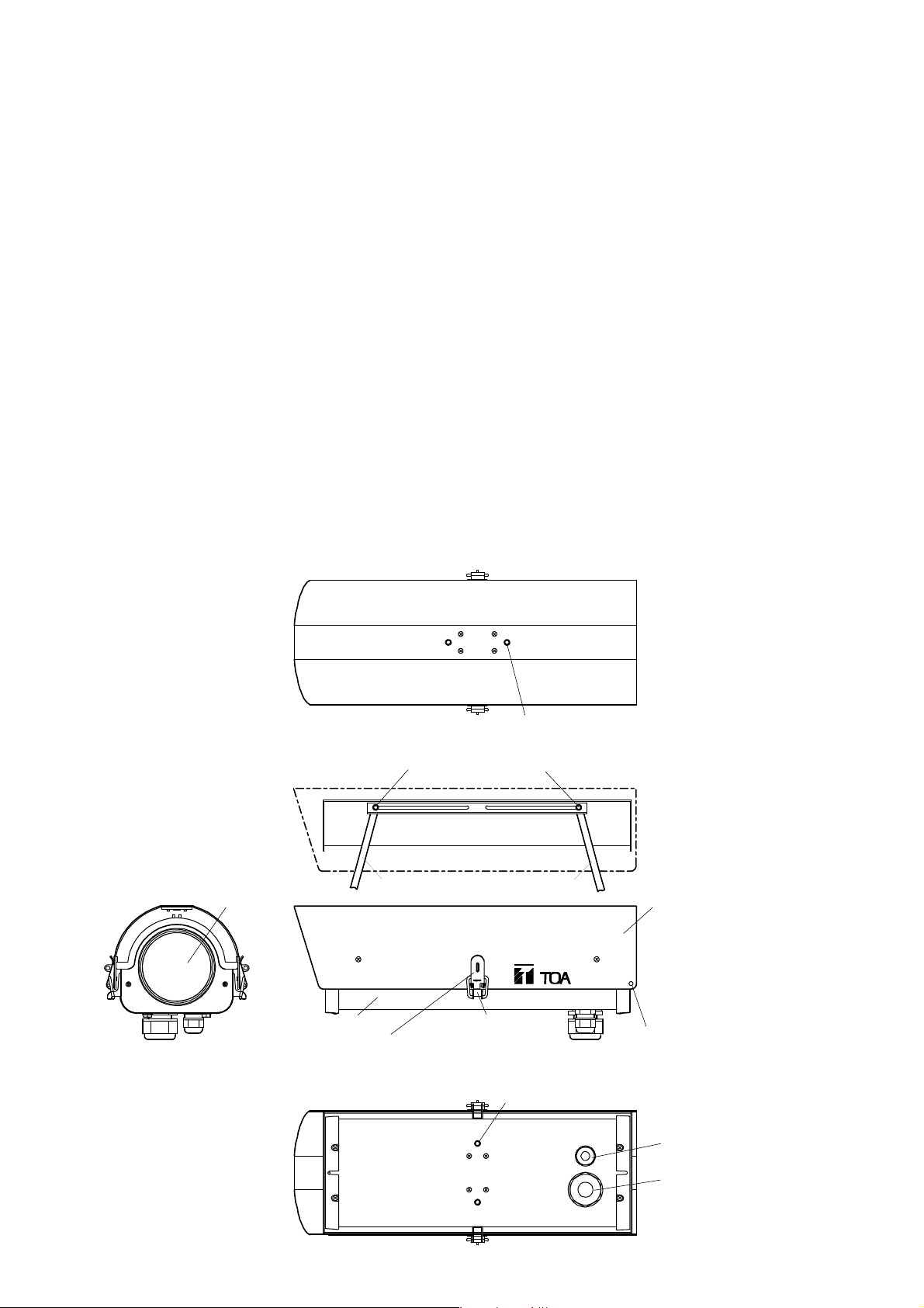
4. NOMENCLATURE
⑩Mounting hole (M6, 2 places)
[Top view]
[Side view]
[Front view]
[Bottom view]
⑥Window
①Base
②Cover (Sunshade)
③Latch catch (with key hole)
④Hook
⑤Suspension wire entry hole
⑫Cord entry bushing
(φ10-φ17 mm)
⑪Cord entry bushing
(φ5-φ9.5 mm)
⑨Mounting hole (M6, 2 places)
(Housing cover is open.)
⑧Stay
⑧Stay
⑦Lock release button
Page 5

5
5. INSTALLATION EXAMPLES
The housing can be mounted to the wall or ceiling using optional brackets and mounting hole ⑨ or ⑩.
5.1. Wall Mounting
5.1.1. Fixed camera orientation
C-BC100K (option)
5.1.2. Use of Pan/Tilt Drive
5.2. Ceiling Mounting
C-BC100T (option)
Use suitable mounting holes
in the pan/tilt drive to mount.
C-BC200K (option)
C-PH200 (option)
Page 6

6
6. OPENING AND CLOSING THE CAMERA HOUSING CO VER (SUNSHADE)
Lock
Lock
LockLock Close Close
Lock
Close
CloseClose
⑧Stay
⑧Stay
⑦Lock release button
⑦Lock release button
Push
②Cover
③Latch catch
(with key hole)
④Hook
①Base
(Sunshade)
Caution
Take care when handling the sharp edges of the metal case, as injuries to the
hand could result.
To prevent potential harm to fingers when closing the cover, do not operate both
stays simultaneously. Instead, be sure to operate the stays individually.
6.1. Standard Installation Procedure
6.1.1. Opening the cover
1. Undo the two cover latches ③.
2. Raise the cover ②.
3. Move the sliding cover stays ⑧ outward until they click into their locking positions.
6.1.2. Closing the cover
1. Press the lock release button ⑦ at the top of each stay and slide the stays individually.
2. Secure the cover in place with the safety latches.
Page 7

7
6.2. Hanging Installation Procedure
6.2.1. Opening the cover
1. While holding the bottom of the camera housing base ① with one hand, undo the cover latches ③ and
slowly lower the base to its full stop.
Note: Failure to hold the base when undoing the latches could result in the base falling suddenly and
possibly damaging the camera.
2. Move the sliding cover stays ⑧ outward until they click into their locking positions.
6.2.2. Closing the cover
1. While pressing the lock release buttons ⑦ individually, raise the camera housing base.
2. Secure the cover in place with the safety latches ③.
7. CABLE ENTRY
1. Two cord entry bushings ⑪ and ⑫ are located at the bottom of the base ①. Select either bushing that
matches with the cable diameter to use.
2. Remove the bushing cap first, and then a waterproof/dustproof rubber sheet from the bushing.
3. Run the cable through the bushing.
4. Turn the bushing cap to adjust the bushing diameter so that there is no gap between bushing and cable. If
the gap is created, wrap the self-adhesive butyl rubber tape round the cable entry area in order to prevent
raindrops from getting into the unit.
5. Ensure that the cable is secured by lightly pulling it.
Page 8

Keep wires as far as possible from a heater
(C-CH100FH only) because fires or electric
shock could result.
To avoid burns, do not touch a heater
(C-CH100FH only).
Be sure to use an optional 24 VAC adapter (CC-5941B) for 24 VAC power.
Failure to do this could cause fires.
8
8. CONNECTIONS
①Base
Heater (C-CH100FH only)
Orientation of lens
Note: Power must be switched on after connection completion.
Fan (not mounted in the C-CH100)
Power input terminal block
⑫Cord entry bushing
⑪Cord entry bushing
8.1. When not Using a Pan/Tilt Drive
Connect the power input terminal block inside the housing's rear panel as follows.
8.1.1. C-CH100FH
The 24 VAC terminal functions as a terminal to relay the 24 VAC camera's power. Switching on the power
after connecting the 24 VAC cable supplies the power to a fan and a heater.
• When connecting the 24 VAC camera • When not connecting the 24 VAC camera
Grounding line 24 VAC power line
To 24 VAC camera's
terminal block
8.1.2. C-CH100
The use of the power input terminal block facilitates connections when using the 24 VAC camera. The
terminal block is not used when the connected camera is not of the 24 VAC type.
• When relaying the 24 AC camera • When not relaying the 24 VAC camera
24 VAC power line
To 24 VAC camera's
terminal block
No wiring is required.
Caution
Grounding line
24 VAC power line
Page 9

9
8.2. When Using the Outdoor Pan/Tilt Drive C-PH200
Modify the housing cable supplied with the pan/tilt drive as follows. Push the cable into the inside through the
cord entry bushing ⑫ located in the bottom panel of the base ①, then make connection as shown in the figure
below or in the figure on page 10.
8.2.1. Modifying the housing cable
Remove the solderless terminal and mount the 4-pin connector supplied with the zoom lens. When a wire
does not snugly fit into the connector terminal hole, extend the wire that mates with the terminal hole. Connect
wire No. 7 to pin No. 1, wire No. 9 to pin No. 3, and wire No. 10 to pin No. 4.
Insulate unused solderless terminals with heat-contracted tube or tape.
8.2.2. Connection when using the housing in combination with the single-cable camera
Wire No.
1 Green
2 Yellow
3 Blue
4 Gray
5 Red
6 Black
7 Purple
8
9
10
11
12
13
Memo: Cable numbers are indicated on the cable.
Purpose of use
AC power (common)
AC power
Camera power Connects to the terminal block on the 24 VAC camera.
Defroster
Wiper
Auxiliary
Lens (common) Connects to the 4-pin connector on the zoom lens.
Iris
Focus
Zoom
Auxiliary
Video output
Orange
White
Peach
Brown
Coaxial cable shielded mesh
Coaxial cable conductor
Wire color
Connects to the 24 VAC terminal (refer to the figure
on page 8) of the power input terminal block.
Not used.
Not used.
Connects to the 4-pin connector on the zoom lens.
Not used.
Connects to the camera's video output terminal.
Connection method
Power input terminal block
inside the housing
When using the C-CH100, wires and
do not need to be connected.
Single-cable camera
Housing cable
Zoom lens
Connector (supplied with the zoom lens)
Page 10

10
8.2.3. Connection when using the C-CH100FH in combination with the 24 VAC camera
8.2.4. Connection when using the C-CH100 in combination with the 24 VAC camera
9. SAFETY WIRE INSTALLATION
A safety wire can be installed to prevent the unit from falling off. When installing, connect a wire hook to the
suspension wire entry hole ⑤ (5 mm in diameter).
Note: Check to confirm the length, diameter, and hook strength of the safety wire before installing since the
impact of the unit's fall onto the floor is quite great.
Attach the BNC plug.
Camera
Zoom lens
Power input terminal block
inside the housing
Remove solderless terminals.
Housing cable
Connector (supplied with the zoom lens)
Attach the BNC plug.
Power input terminal block
inside the housing
No wiring is required.
Camera
Zoom lens
Connector (supplied with the zoom lens)
Remove solderless terminals.
Housing cable
Page 11

11
10. CAMERA INSTALLATION PROCEDURE
Camera with a standard or wide angle lens
Camera with a zoom lens
Butterfly bolt
Auxiliary mounting holes
for butterfly bolts
①Base
Lens orientation
Camera mounting plate
Camera mounting bolt
Plain washer
Spring washer
1. Detach the camera mounting plate from the housing base ①.
2. Mount the camera on the camera mounting plate and secure the camera to the mounting plate using the
supplied camera mounting bolt, plain washer and spring washer. When an adequate view angle is not
available with the preset butterfly bolt position on the camera mounting plate, use the auxiliary holes.
3. Perform wiring to the camera.
4. Using the butterfly bolts, fix the camera-installed mounting plate to the housing base so that the lens is
positioned as close to the housing window as possible.
Page 12

C-CH100 C-CH100FH
–
24 VAC, 50/60 Hz
–
25 W
On-off control by thermostat
–
Fan: Turns on at over approx. 26°C
Heater: Turns on at under approx. 10°C
IEC529 IP33
General outdoor environments
(
except seaside and industrial districts where the unit is subject to
corrosion, and heights that expose the unit to strong wind pressure
)
–10°C to +45°C –20°C to +45°C
Under 98%RH
Panel : Die-cast aluminum, light beige, paint
Other parts : Aluminum, off white, paint
172 (W) x 128 (H) x 400 (D) mm
80 (W) x 77 (H) x 305 (D) mm
2 kg 2.2 kg
Printed in Japan
133-12-543-6B
11. SPECIFICATIONS
Model No.
Power Source
Power Consumption
Fan/Heater Operating
Temperature
Waterproof Resistance
Application
Operating Temperature
Operating Humidity
Finish
Dimensions
Internal Capacity
Weight
Note: The design and specifications are subject to change without notice for improvement.
• Accessories
Camera mounting bolt (U1/4 x 10) ........... 2
Plain washer ............................................ 2
Spring washer .......................................... 2
• Option
Ceiling suspension bracket : C-BC100T
Wall mounting braket : C-BC100K
 Loading...