

Page 1
ENGLISH
COMBINATION CAMERA
OUTDOOR COMBINATION
CAMERA
QUICK MANUAL
C-CC514, C-CC564
C-CC574, C-CC714
C-CC764, C-CC774
TABLE OF CONTENTS
Manual ······································································ 12
MENU SCREEN CONFIGURATION·························2
FUNCTION TABLE
Preset ···································································4
ID Setting ·································································· 4
Camera setting (CAM) ············································ 5
Camera setting (POS) ············································· 8
Auto mode ································································ 9
Alarm ·······································································10
AUX ·········································································11
Timer ·······································································11
Thank you for your purchasing TOA’s Combination Camera. Please carefully follow the instructions in
this manual to ensure long, trouble-free use of your equipment.
Maintenance ···························································· 12
HOW TO SETTING
1. BEFORE SETTING ············································ 15
2. ENTERING CAMERA MENU SCREEN ··········· 17
3. SELECTING THE LANGUAGE ························ 18
4. SETTING PRESETS ··········································19
5. MAINTENANCE SETTINGS ·····························21
RETURN ALL SETTINGS TO INITIAL
6.
STATUS SET BY THE FACTORY
·····················21
Page 2

→PRESET
NEXT PAGE
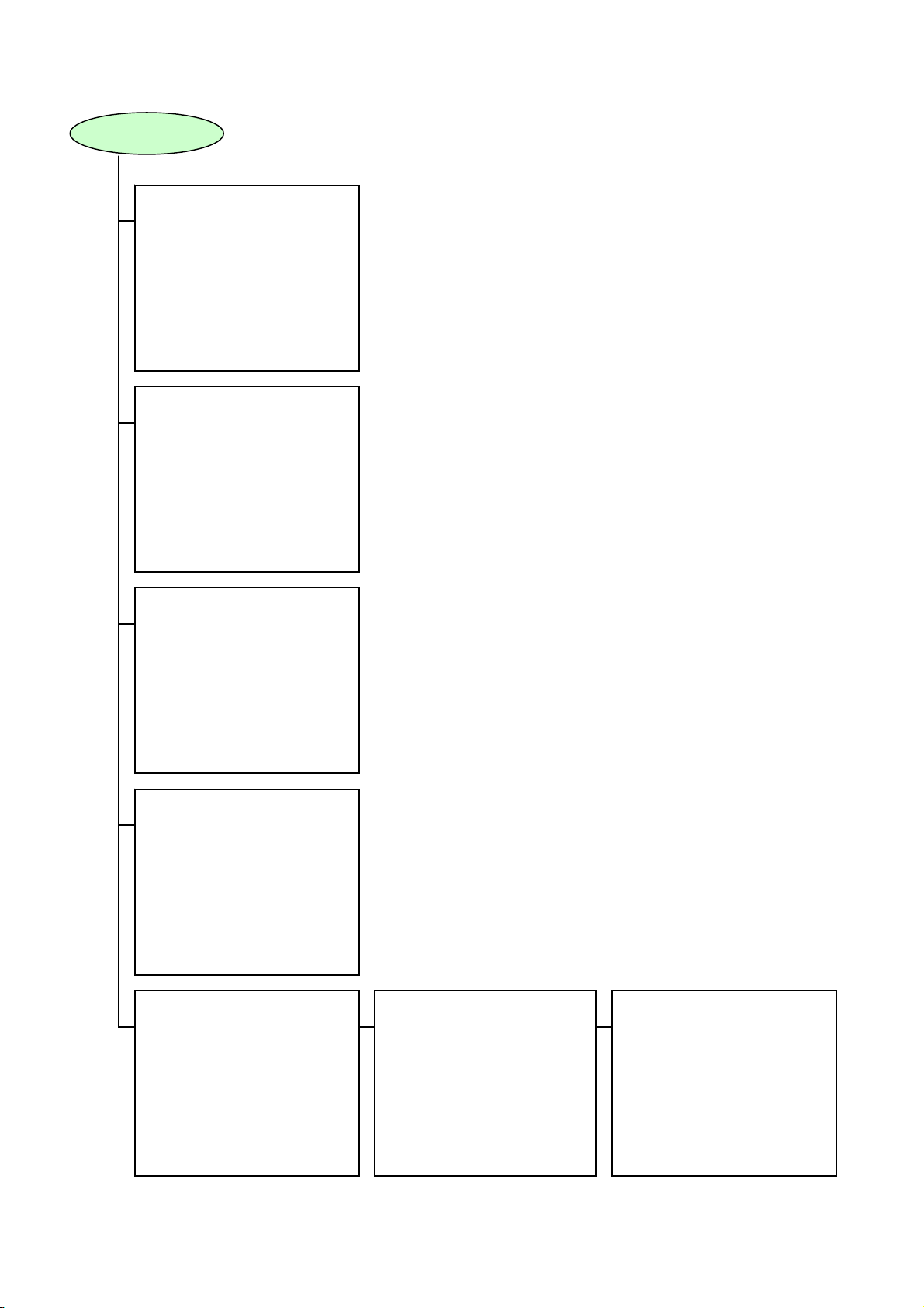
MENU SCREEN CONFIGURATION
CAMERA MENU
ID SETTING
CAMERA SETTING CAM
AUTO MODE
ALARM
AUX
TIMER
MANUAL
MAINTENANCE
LANGUAGE ENGLISH
*PRESET*
→MEMORY
READJUST ALL POS ***POS
MEMORY RESET
MEMORY ALL RESET NO
AUTO RETURN OFF
HOME 1POS
PRESET FREEZE OFF
*ID SETTING*
→DISPLAY
ID SETTING
LOCATION
FRAME ADJUST
ZERO POINT
*CAMERA SETTING*
→WHITE BALANCE ATW →E-ZOOM x12
R---*---B
BACKLIGHT OFF
BRIGHTNESS ----*--- DAY/NIGHT NORMAL
AUTO FOCUS ONE PUSH
AGC AUTO
SLOW SHUTTER x32
SHUTTER SPEED NORMAL
NEXT PAGE
*AUTO MODE*
→AUTO KEY AUTO PAN
AUTO PAN
SEQUENCE
TRACE TRACE1
TRACE1 PAUSE TIME 1s
TRACE2 PAUSE TIME 1s
TOUR
*CAMERA SETTING*
ENHANCER ----*--- CHROMA ----*----
SYNC INT
EIS OFF
SENSITIVITY OFF
RESET(CAM SETTING) NO
FRONT PAGE
2
Page 3
S
FRONT PAGE
*ALARM*
→INPUT
REPORT
ACTIVE STATE
PRIORITY
ACTION
INTERVAL
RESET ACTION
ALARM DATA
*AUX*
-----------------------------------------
→AUX1
AUX2
*TIMER*
→PROGRAM
TIME DISPLAY 12H
DATE DISPLAY MM/DD/YY
ENTER TIME
ENTER DATE
SUMMER TIME OFF
*MANUAL*
→ZOOM SCALABLE P/T ON
P/T LIMIT OFF
P/T LIMIT SETTING LEFT
MAX P/T SPEED 120
FLIP OFF
UP LIMIT ON
*MAINTENANCE*
1111
PASSWORD
↑
*MAINTENANCE*
→INITIALIZE NO
REFRESH
PASSWORD ON
MOTOR POWER OFF
FACTORY PRESET NO
AUTO ADJUST OFF1
DATA BACKUP
NEXT PAGE
*MAINTENANCE*
→MOTION DETECTION 1PO
PRIVACY MASK
FRONT PAGE
3
Page 4
A
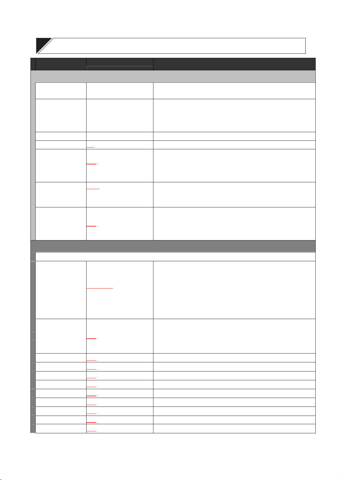
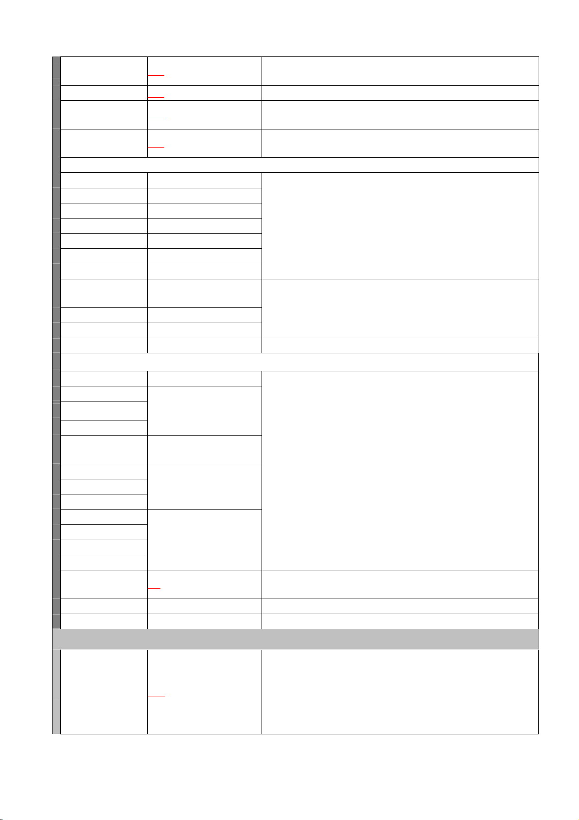
FUNCTION TABLE
Commands Keystrokes Description
PRESET
MEMORY
READJUST ALL POS
MEMORY RESET
MEMORY ALL RESET
AUTO RETURN
HOME
PRESET FREEZE (*1)
POS 1-255 - FINE SETTING
POS 1-255
POS 1-255 The stored position is erased.
/YES Deletes all preset position data.
NO
/5s/10s/15s/20s/30s/45s/
OFF
1min/3min/5min
/2POS/254POS/255POS/
1POS
UTO PAN/SEQUENCE/
TRACE1-2/TOUR1-16
/ON
OFF
Settings such as camera direction, lens angular field of view, and focus can
be preset in advance. Up to 255 positions can be set.
This function simultaneously resets all preset camera panning positions.
The deviation of one camera position is measured, based on which all other
positions are globally corrected. When performing this global correction, use
the position on the telescope side whenever possible.
This function is used to determine operation when the camera is not
controlled at all. The camera automatically reverts to the initially set program
when the preset period of time elapses after the controller’s control has been
finished.
Designate the program the camera automatically returns to.
Freezing the screen immediately before replaying preset memory blanks
out the view of the camera’s movement between camera positions. It is
recommended that the preset memory freeze function also be used
together when using the privacy masking function.
ID SETTING
DISPLAY
ALL
ADDRESS
CAMERA
POSITION
TRACE
AUTO PAN
TOUR
HOME
ALARM
SECTOR
AUX
Contents or time to be displayed can be set by selecting “Display” on the ID
setting screen.
INDIVIDUAL
OFF/ON
OFF
OFF
OFF
OFF
OFF
OFF
OFF
OFF
OFF
OFF
/1s/3s/5s/10s/
/ON/1s/3s/5s/10s
/ON/1s/3s/5s/10s Displays the Camera Title.
/ON/1s/3s/5s/10s Displays the Position title (1 – 255).
/ON/1s/3s/5s/10s Displays the Trace title (1 – 2).
/ON/1s/3s/5s/10s Displays the Auto-Pan title.
/ON/1s/3s/5s/10s Displays the Tour title (1 – 16).
/ON/1s/3s/5s/10s Displays the Home Position title (1 – 3). Up to 3 titles can be set.
/ON/1s/3s/5s/10s Displays the Alarm title (1 – 8).
/ON/1s/3s/5s/10s Displays the title for the sectors split in the panning direction.
/ON/1s/3s/5s/10s Displays the AUX contact output title (1 – 2).
OFF : Nothing is displayed.
ON : Every ID are all displayed.
1s, 3s, 5s, 10s : ID is displayed for a set length of time.
INDIVIDUAL : Performs display settings for each ID.
Displays the camera address and camera position No. Title length can be
freely adjusted from 3 to 7 digits.
(Camera address: DIP SW1: for setting, factory-preset: 001)
[ ***-*** ] Camera address - Position number
4
Page 5
ANGLE
A
A
A
ZOOM
DATE
TIME
ID SETTING
CAMERA
POSITION
TRACE
AUTO PAN
TOUR
HOME
ALARM
SECTOR
1)SECTOR SETTING
2) ID SETTING
AUX
LOCATION
ADDRESS
CAMERA
POSITION
TOUR
HOME
ALARM
SECTOR
AUX
ANGLE DISP
ZOOM DISP
DATE DISP
TIME DISP
PATTERN CLEAR
FRAME ADJUST
ZERO POINT
/ON/1s/3s/5s/10s
OFF
/ON/1s/3s/5s/10s Displays the Electronic Zoom. Fixed 3-charactors.
OFF
/ON/1s/3s/5s/10s
OFF
/ON/1s/3s/5s/10s
OFF
***POS 1-255
TRACE 1-2
TOUR 1-16
HOME 1-3
LARM 1-8
SECTOR SETTING/ID
SETTING
FIX/EACH/CLEAR 1-8
SECTOR 1-8
UX 1-2 The ID setting screen is displayed. Input the title character.
LOCATION SETTING
LOCATION SETTING/
LENGTH SETTING
LOCATION SETTING/
LENGTH SETTING - HOME1-3
LOCATION SETTING/
LENGTH SETTING
LOCATION SETTING
/YES
NO
Adjust the character display position.
Change the origin point of the angle (Zero point) display.
Displays the coordinate. Pan (0 to 359°)/ Tilt (5 to -185°) fixed 8 characters.
[ ***/-*** ] Pan angle (0 to 359°)/ ±Tilt (5 to 185°)
Displays the date in accordance with the date setting (timer setting) format.
Fixed 8-charactors.
Displays the time in accordance with the time (hour, minute) setting (timer
setting) format. (Format: fixed 5 or 7-charactors)
The ID setting screen is displayed.
Input the title character.
The range of the sector is set or is cleared.
The sector title is set.
Setting North permits the direction to be automatically divided into 8 sectors.
(north, north east, east, south east, south, south west, west, and north west)
Setting title display position and its length.
All set display positions and lengths can be reset to initial factory-preset
conditions.
CAMERA SETTING (CAM)
The white balance may be set to either AWB or ATW. (factory default: ATW)
WHITE BALANCE
TW/AWB
ATW : The camera adjusts its white balance setting according to fluctuations in
the color temperature of the subject’s illumination.
AWB : The camera uses a fixed white balance setting regardless of fluctuations in
the color temperature of the subject’s illumination.
5
Page 6
BACKLIGHT
BRIGHTNESS
DAY/NIGHT (*1)
/WIDE DYNAMIC (*1)/
OFF
WIDE DYNAMIC2 (*3)/
PATT ER N1 -3
9steps
NORMAL
MOTION
/ON/OFF/COLOR/
The Backlight Compensation function makes the image displayed on the
screen easier to see when there is strong light behind the subject. (factory
default: OFF)
OFF :
Turns the Backlight Compensation function off. This is the setting usually
used.
WIDE DYNAMIC
Allows backlight compensation that prevents the subject from becoming too
dark or the surrounding background from becoming too white.
Try using WIDE DYNAMIC as the initial setting to compensate for
backlighting.
WIDE DYNAMIC2 :
Allows objects in a dark location with a bright background to be
distinguished, which cannot be achieved by Wide Dynamic. However, the
bright background may look darker.
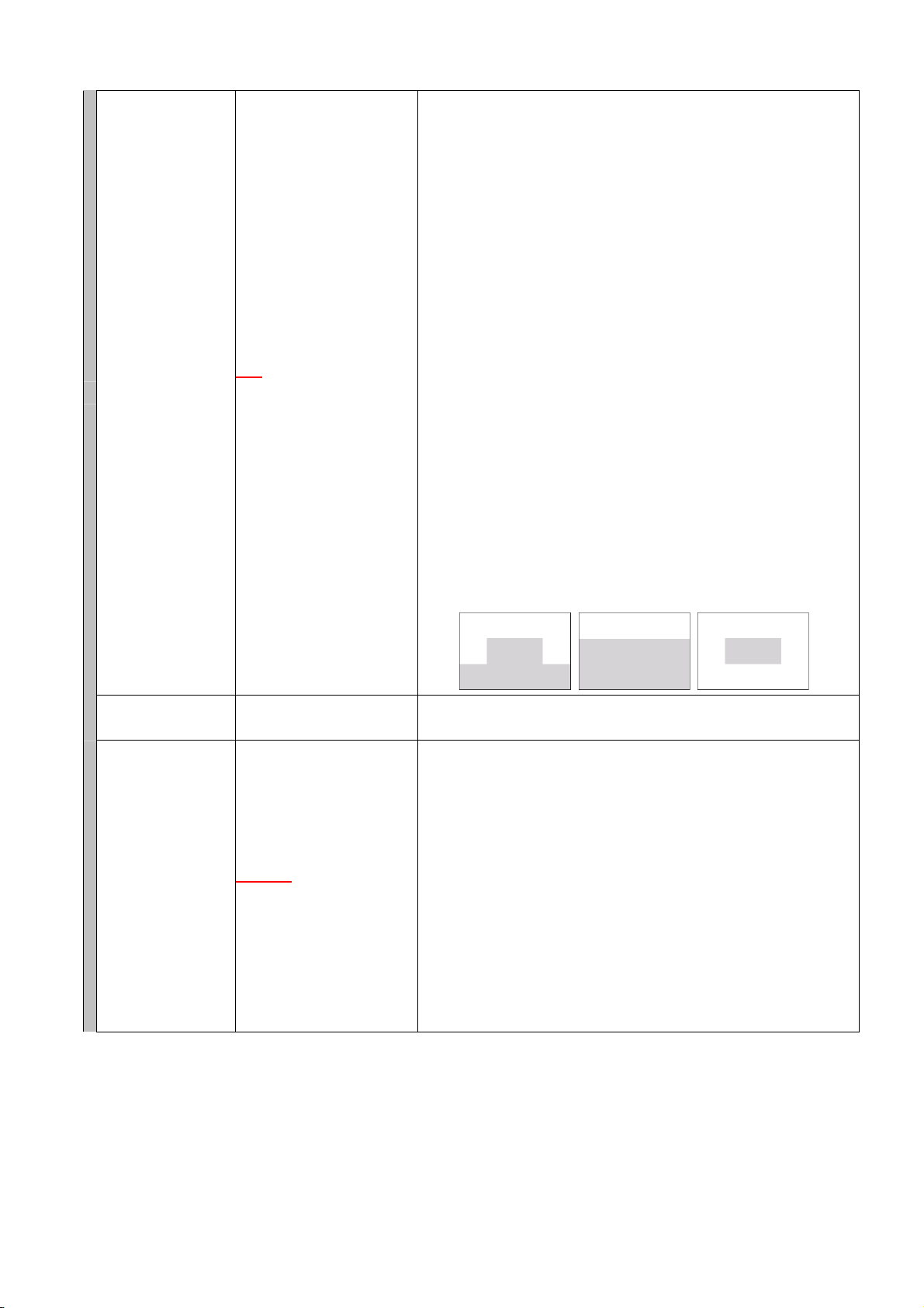
PATTERN1, PATTERN2 or PATTERN3 :
Turns the Backlight Compensation function on. This automatically adjusts
the overall brightness so that brightness is optimized for easier viewing in the
screen areas indicated in shaded region. Select 1, 2, or 3 depending on
which makes the intended subject the easiest to see.
PATTERN 1 PATTERN 2 PATTERN 3
The brightness of the camera image can be adjusted to suit user
preferences.
This function gives operation priority to black & white mode or slow shutter
mode depending on the subject brightness.
(factory default: NORMAL)
COLOR : Slow shutter mode takes operating precedence. When a moving
subject is photographed, the picture is like the one shot during camera
movement, but can be viewed in color.
MOTION: Black & white mode takes operating precedence. Even if a
moving subject is photographed, clear pictures can be provided.
NORMAL : Balanced black & white mode and slow shutter operation.
ON : Turns on black & white mode, and always provides black and
white pictures.
OFF : Turns off black & white mode and always provides color pictures.
:
6
Page 7

AUTO FOCUS
A
AGC
SLOW SHUTTER
SHUTTER SPEED
E-ZOOM
ENHANCER
CHROMA
(Factory default: ONE PUSH)
ONE PUSH: Auto focusing is operated when the Auto-focus key is pressed.
STOP AF : Auto focusing is automatically operated after the camera scene
or angle of view has been changed. The STOP AF function does not work
ONE PUSH
CONTINUOUS
UTO/MAX/OFF
X32
NORMAL
( PL:1/150) / 1/250 / 1/500 /
1/1000 / 1/2000 / 1/4000 /
1/10000
X12
X8CONT/X4CONT/X2CONT/
OFF
9steps
9steps The chroma may be adjusted to suit user preferences.
/STOP AF/
/OFF/X2/X4/X8/X16
/ 1/100 / NT:1/120
/X8/X4/X2/X12CONT/
when the Focus key is used. Pressing the Auto-focus key again will put the
camera in the STOP AF mode.
CONTINUOUS: The Auto-focus function is always operated. However, it
cannot be used after preset playback (including Home Position). In this
event, the Auto-focus function can be used through manual operations.
Also, the Auto-focus function cannot be used if the Auto-focus key is
pressed, and can be used if the Auto-focus key is pressed again.
(Factory default: Auto)
AUTO: Automatically adjusts the gain depending on the subject’s brightness
level.
OFF : Disables the automatic gain control function.
MAX : Used when the subject brightness is insufficient when in AUTO
mode.
(Factory default: X32)
The camera is automatically placed in slow shutter mode depending on
subject brightness.
The Slow Shutter function cannot be used when set to OFF.
The shutter speed can be fixed. (Factory default: NORMAL)
Electronic Zoom is used to enlarge the view of the subject more than is
possible with normal optical zoom. A maximum enlargement can be set for
the Electronic Zoom. It is also possible to set the zoom to stop for a moment
before switching from optical to electronic zoom. (factory default: X12)
OFF : Turns the Electronic Zoom function off.
X2, X4, X8, X12 :
Engages the Electronic Zoom function. The numbers indicate the maximum
electronic zoom enlargement. When the Zoom key (telephoto) is pressed
and held, zooming stops for a moment before switching to electronic zoom.
Pressing the Zoom key (telephoto) again continues the image enlargement
via Electronic Zoom.
X2 CONT, X4 CONT, X8 CONT, X12 CONT :
Engages the Electronic Zoom function. The numbers indicate the maximum
electronic zoom enlargement. When the Zoom key (telephoto) is pressed
and held, zooming switches from optical to electronic zoom without stopping
so that the zooming proceeds continuously until it reaches the maximum
enlargement.
The Enhancer function enhances the contours within the camera image. It
may be adjusted to suit user preferences.
7
Page 8

SYNC
EIS (*3)
SENSITIVITY (*3)
RESET
(CAM SETTING)
/LL –
INT
NT60Hz:00-82/PL50Hz:00-99
/ON1/ON2
OFF
/ON
OFF
/YES
NO
The camera’s sync system can be switched to the system that uses the
power frequency. It is also possible to adjust the phase.
(Factory default: INT.)
INT: Represents the internal sync system. Select this setting when only a
single camera is used and it is not necessary to synchronize it with other
camera.
LL : Represent the power sync system. Select this setting when
synchronizing 2 or more cameras using the power frequency. Note that
when the screen is switched by the sequential switcher, etc., the picture may
be distorted depending on the camera installation conditions, such as the
distance to the power source. In such cases, adjust the phase to prevent the
picture distortion from occurring. The phase can be adjusted in 83 – step
ranging from “00” to “82” for NTSC system and in 100 – step ranging from
“00” to“99” for PAL system.
Screen vibrations can be reduced. (Factory default: OFF)
OFF: No image stabilization performed.
ON1: Use this mode for relatively quick screen vibration.
ON2: Use this mode for relatively slow screen vibration.
This function increases sensitivity. Selecting ON doubles the sensitivity.
(Factory default: OFF)
Settings of each item on the Camera Setting screen can be reset and
returned to initial status set by the factory.
CAMERA SETTING (POS)
IMAGE
W.B .
BACKLIGHT
BRIGHTNESS
DAY/NIGHT
SHUTTER SPEED
AGC
SLOW SHUTTER
ENHANCER
CHROMA
LOCATION
ADDRESS
CAMERA
POSITION
TOUR
HOME
ALARM
SECTOR
AUX
ANGLE DISP
ZOOM DISP
DATE DISP
TIME DISP
PATTERN CLEAR
PRESET MEMORY
COMMON
Setting procedures and option
contents are the same as
those of "Camera Settings".
COMMON
Setting procedures and option
contents are the same as those
of "ID Display Position Settings".
/SCENE1-10 Changing arbitrary position picture quality using the Scene function.
/PATTERN1-10
Such picture quality settings as white balance, backlight compensation,
brightness, day & night, shutter speed, AGC, slow shutter, enhancer, and
chroma can be preset and stored for up to 10 different scenes (1–10).
Picture quality can be changed by selecting one of the preset 10 scenes at
each individual position.
Changing the ID display position for arbitrary camera position using the
Pattern function.
All ID display positions can be preset and stored in 10 different patterns
(1–10). All ID display positions can be changed by selecting one of the 10
patterns at each individual position.
8
Page 9

A
play
AUTO MODE
AUTO KEY
AUTO PA N
OPTION
PAU SE TIME
SPEED
DIRECTION
LIMIT
LIMIT RESET
One of the following 5 automatic functions can be assigned to the Auto key:
(factory default: AUTO PAN)
AUTO PAN: Auto Pan operation begins when the Auto key (or Auto Pan
key) is pressed.
UTO PA N/SEQUENCE/
TRACE1-2/TOUR1-16
REVERSE
PIVOT
/2s/3s/5s/10s/20s/30s
1s
7steps Select the Auto Pan speed.
LEFT
LEFT/RIGHT
LEFT/RIGHT
/SKIP/RANDOM/
/RIGHT
SEQ : Sequence operation begins when the Auto key (or Auto Pan
key) is pressed.
TRACE1 : Trace 1 operation begins when the Auto key (or Auto Pan key)
is pressed.
TRACE2 : Trace 2 operation begins when the Auto key (or Auto Pan key)
is pressed.
TOUR1-16 : Tour operation begins when the Auto key (or Auto Pan key) is
pressed.
The Auto Pan function horizontally moves (pans) the camera between set 2
points.
Set the Auto Pan operations. (factory default: REVERSE)
REVERSE: Setting both the left and right limits in the Auto Pan limit setting
causes the camera to automatically pan between the 2 set points.
SKIP : If both the left and right limits are set in the Auto Pan limit setting,
the Auto Pan operation begins after returning from an endpoint to a start
point. If, for example, the Auto Pan rotation direction is set for right, after the
intermediate panning point between the left and right limits is first played
back, the camera automatically pans in the right direction. As soon as the
camera reaches the right limit, it is instantly returned to the left limit to begin
the Auto Pan operation toward the right limit again.
RANDOM: The camera repeats pan and stop operation between two
predetermined points at random timing.
PIVOT : After panning for a distance equal to the horizontal lens view
angle, the camera stops for a set period of time and then again rotates for a
distance equal to the lens view angle. This operation is repeated between
the two predetermined points.
Setting the Auto Pan stop duration at an endpoint.
(Factory default: 1s)
When the direction of Auto Pan rotation is not set, the Auto Pan camera
continues to rotate only in the oneway direction and is not reversed. When
either the left or right limit or both limits are set, the direction set here means
the direction in which the camera first moves. (Factory default: LEFT)
Set both the left and right limits of Auto Pan rotation.
When only either the left or right limit is stored, the Auto Pan operation
returns at a set point according to the setting of the direction of Auto Pan
rotation, that is, the camera is reversed for every 360°rotation. When the
tilting position, zoom, and focus position differ between the left and right
limits, data last set are stored. In this event, an intermediate panning point
between both limits, and last set tilting position, zoom, and focus position are
ed back, and then the Auto Pan operation begins.
first
9
Page 10

SEQUENCE
MODE
STOP TIME
TRACE
TRACE1 PAUSE TIME
TRACE2 PAUSE TIME
TOUR
ORDER
NORMAL
10s
TRACE1
CLEAR2
1s/2s/3s/5s/10s/20s/30s
Tour function can be operated in combination of Preset, Trace, etc.
number 1-16 Set the operation to be programmed to each Tour Nos. 1 – 16.
/RANDOM/TEST
/20s/30s/1s/2s/3s/5s
/TRACE2/CLEAR1/
Choice Selected contents 1 Selected contents 2
***POS
AUX1 ON/AUX1 OFF/
AUX2 ON/AUX2 OFF
TOUR 1 - 16
TRACE 1 - 2
B/W ON / B/W OFF – –
STOP – –
The Preset Sequence function displays set positions of one same camera
on the monitor in predetermined sequential order.
Sets the sequence order. (factory default: Normal)
NORMAL: Playbacks preset-memory stored camera positions in numerical
order.
RANDOM: Playbacks preset memory store camera positions in random order.
The stop duration for each position is determined in random order.
TEST : Playbacks preset-memory stored camera positions in numerical
order. The stop time for each position is set to 1 second and the
sequence will be terminated after making a position circuit.
Set the interval of sequential playback duration.
(Factory default: 10s)
The Trace function follows a set path.
When continuously playing back the trace operations with the Auto key (or
Auto-Pan key), the stop duration interval between start position and end
position of one trace operations can be set. (Factory default: 1s)
SP360/SPA/SP8/SP16/SP24/
SP40/SP60/SP90/SP120/SP160/
SP240
– –
1TIME/2TIME/3TIME/4TIME/
5TIME
1TIME/2TIME/3TIME/4TIME/
5TIME
10s/20s/30s/1s/2s/3s/5s
–
–
INSERT
RESET
ALARM
INPUT
REPORT
ACTIVE STATE
10
Inserting operation into Tour program.
Deleting Tour Program.
Of alarm inputs, designate the input number to which an alarm signal is
number 1-8: OFF/ON
number 1-8: OFF/ON Specify the terminal that transmits alarm input information to the controller.
number 1-8: CLOSE/OPEN
actually connected. Unless the alarm input settings are performed, alarm is
not activated even if the alarm signal is received.
Specify whether to receive alarm signal information with make or break
contact.
Page 11

A
A
A
A
A
A
A
PRIORITY
ACTION
INTERVAL
RESET ACTION
ALARM DATA
number 1-8:
LARM/MANUAL/TIMER
– 3s/5s/10s/15s/20s/30s/
45s/1min
number 1-8: OFF/***POS/
UX1 ON/AUX1 OFF/
UX2 ON/AUX2 OFF/
TOUR1-16/TRACE1-2/HOME
number 1-8: 3s/5s/10s/15s/20s/
30s/45s/1min/3min/5min/LEVEL
number 1-8: OFF/***POS/
UX1 ON/AUX1 OFF/
UX2 ON/AUX2 OFF/
TOUR1-16/TRACE1-2/HOME
Specify whether to display the set alarm ID on the screen and forcibly
execute alarm operation or give priority to operation when an alarm signal is
received.
ALARM : Ignores commands from the controller and starts alarm operation.
MANUAL : Initiates alarm operation only while operating the initial program.
TIMER : Initiates alarm operation after the preset time elapses. When the
initial program is operating, alarm operations are initiated
immediately.
Specify the camera’s operation (Action) when an alarm signal is received.
Specify the period of time that alarm conditions are maintained when an
alarm signal is received.
Specify the camera’s operation when alarm conditions are reset.
Alarm log recorded most recently takes precedence.
Up to 16 latest logs can be displayed.
AUX
AUX1
AUX2 (*2)
TIMER
PROGRAM
TIME DISPLAY
DATE DISPLAY
ENTER TIME
ENTER DATE
INITIAL STATE-OFF/ON
ON STATE-CLOSE
TYPE - MOMENTARY/LATCH
ON TIME
- NO LIMIT/1s/2s/3s/5s/
10s/20s/30s
TYPE - MOMENTARY/LATCH
ON TIME
- NO LIMIT/1s/2s/3s/5s/
10s/20s/30s
number 1-16: REPEAT
- OFF/DAILY/M-F/WEEKLY
TIME
CTION - ***POS/AUX1 ON/
UX1 OFF/AUX2 ON/AUX2
OFF
TOUR1-16/TRACE1-2/HOME
CLEAR - NO/YES
12H/24H The time display can be set to 12-hour or 24-hour display formats.
MM/DD/YY, DD/MM/YY,
YY/MM/DD
Time can be set in the order of hour/ minute/ second.
/OPEN
The AUX1 is an open collector type contact. The controller’s auxiliary switch
is used to control it.
The AUX2 is a relay type contact. The controller’s defroster switch is used to
control it.
Predetermined operations can be set to be performed at preset times.
Select the program from Preset Memory, Home Position Change, Auto
Operation, and Contact Control. The programs can also be set for several
types of operation, including “one time only,” “daily preset times,” and
“weekly.” Up to 16 programs can be set for a timer.
The date display can be set for month/day/year, day/month/year or
year/month/day display formats.
The display formats of Month/Day/Year or Day/Month/Year follows the date
display setting.
11
Page 12

SUMMER TIME
MANUAL
ZOOM SCALABLE
P/T
P/T LIMIT
P/T LIMIT SETTING
MAX P/T SPEED
FLIP
UP LIMIT
Enables summer time between 2:00 AM on the set first day of summer time
and 2:00 AM on the last day.
OFF/ON/SET
- FIRST DAY/LAST DAY
ON/OFF
OFF/ON/CLEAR
LEFT/RIGHT/UP/DOWN Set the pan and tilt rotation range.
120/160/240/360/A/8/16/24/
40/60/90
OFF/AUTO/MECHANICAL
ON/OFF
OFF: Disables summer time.
ON : Enables summer time.
SET: Performs summer time setting.
Rotation speed relative to zoom ratio can be set to OFF. Select OFF when
the function of reducing the rotation speed during telescopic operation is not
needed.
Designate the pan and tilt rotation range limits.
OFF : Disables rotation limits.
ON : Enables rotation limits.
The camera does not tilt between –90°and –185°.
CLEAR: Deletes all rotation limit positions.
Set the maximum speed of panning and tilt in manual operation.
The larger the figure is, the faster pan and tilt speeds.
“A” : Operates at a constant speed of “25” without acceleration or
deceleration.
This function flips the image shown on the monitor when the camera stops
executing a tilt operation (rotating the camera vertically) between –90° to
–185°. (Factory default : OFF)
OFF : Turns the Flip function off.
AUTO: Turns the Flip function on.
MECHANICAL: Turns the Mechanical Flip function on. This function flips the
image shown on the monitor by rotating the camera 180°in the panning
direction while its tilt operation (rotating the camera vertically) is going on at
the range of –90°.
When the camera’s vertical rotation is set to horizontal (0°or –180°) with the
joystick, the camera’s case may appear at the top of the screen, causing a
dark patch. Setting this switch to the ON position limits the tilt angle, as
shown at right, and reduces the amount of case visible onscreen. (Factory
default : ON)
MAINTENANCE
INITIALIZE
NO/YES
12
In the combination camera’s preset memory playback function, a stepping
motor is controlled by open loop. Therefore, if the camera is used for long
uninterrupted periods of time, the camera position may deviate from the
original settings. In such cases, deviation can be corrected with
re-initialization.
Page 13

REFRESH
PASSWORD
MOTOR POWER
FACTORY PRESET
AUTO ADJUST
DATA BACKUP
MOTION
DETECTION
(*1)
If the camera is used for long uninterrupted periods of time, the camera
position may deviate when the position is played back. In such cases,
deviation can be corrected using the auto-refresh function. Also, if the
camera’s horizontal rotation contacts get dirty, the displayed image may
OFF/EVERY/SUN-SAT
ON/OFF/SET
OFF/ON
NO/YES Used to return all settings to initial status set by the factory.
OFF1/OFF2/ON1/ON2
MAIN→BACKUP /
MAIN←BACKUP
1POS/2POS/254POS/255POS
become distorted or manual horizontal rotation interrupted. In such cases,
the auto-refresh function cleans horizontal rotation contacts periodically.
OFF : Not refreshed.
EVERY : Refreshes at set time each day.
SUN-SAT : Refreshes at set time and day each week.
Set the password to be required when activating Maintenance menu
screen.
ON : When “ON” is selected, the Password Setting screen will be displayed
when displaying the Maintenance screen.
OFF: The selection of “OFF” will establish no password required when
entering the Maintenance screen.
SET: Displays the Password setting screen.
When the preset camera position frequently deviates from its original
position, the symptom may be improved by setting the Motor Power to ON.
Positional deviation can be set to be automatically corrected when it occurs.
Perform correction when the camera has rotated to some degree of
deviation.
OFF1: No automatic correction.
OFF2: Displays a circle indication at the upper center of the screen if
positional deviation is detected.
ON1 : Automatically corrects positional deviation.
ON2 : Displays a circle indication at the upper center of the screen if
positional deviation is detected, and deletes the indicator when deviation is
corrected.
Setting data can be transferred to or read out from the backup memory.
However, data cannot be backed up for Privacy Masking, alarm logs, date,
and time. When setting data has been transferred from the backup memory
to the main memory during repair or replacement of equipment, set the
preset memory again. Since each camera’s basic information is backed up
in preset memory, preset positions can deviate if the data is transferred to
another camera.
When any movement is detected within the set area, preset positions can
be played back, the tour sequence is called up, or the contact opened and
closed. This function is not a dedicated device for prevention of fire, etc. TOA
takes no responsibility for any incidental loss or accidents. While the motion
detection function is operating, certain other functions (slow shutter, day &
night, Privacy Masking) cannot be used.
13
Page 14

A
A
A
A
FUNCTION
REA1-8
OFF/ON-L/ON-M/ON-H
REA1-8
OFF/***POS/TOUR1-16/
ACTION
TRACE1-2/ALARM1-8/
UX1 ON/AUX1 OFF/
UX2 ON/AUX2 OFF
PRIVACY MASK (*1)
SET/C LE AR /PATT ER N
SET
CLEAR
MASK1-8
MASK1-8 - NO/YES Clearing the Privacy Masking.
PATTERN
LANGUAGE
FULL/HALF
ENGLISH/DEUTSCH/
FRANÇAIS/ITALIANO
(*1) C-CC564 , C-CC574 , C-CC764 , C-CC774
(*2) C-CC564 , C-CC574
(*3) C-CC574 , C-CC774
Set locations for motion detection sensors.
OFF : No movement detected.
ON–L: Detects movement at low sensitivity.
ON–M: Detects movement at intermediate sensitivity.
ON–H: Detects movement at high sensitivity.
Set operations that will take place when sensors are activated.
OFF : No operation.
***POS : Presets to the designated position.
TOUR1–16: Activates the selected camera’s Tour sequence.
TRACE1, TRACE2: Activates selected trace functions.
AUX1 ON, AUX1 OFF, AUX2 ON, AUX2 OFF
: Performs specified operations at specified contact numbers.
ALARM1–8: Activates the alarm and performs the same operation as when
an alarm signal is received at the specified alarm number.
When there are locations that are required to be kept out of view in a
camera scene, up to 8 of such locations can be masked out of view.
Setting Privacy Masking to ON automatically disables the Auto-Flip function.
Only two ( C-CC564 、 C-CC764 ) or only four ( C-CC574 、C-CC774 )
masking areas can be displayed on the same screen. Depending on the
masked area and its size, the number of masking areas that can be set
decreases.
Two different patterns are available: One is a Full pattern that completely
hides the masked area and the other is a Half pattern that makes it
semi-transparent.
14
Page 15

HOW TO SETTING
1. BEFORE SETTING
1.1. Address Display When Turning Power On
When the camera’s power is turned on, the camera performs the initial operation (initializing operation) and
simultaneously the camera address appears on the monitor. After the completion of initial operation and peripheral
device connections, the camera can be controlled and the camera address screen will disappear.
Notes
• In the place of “***”, a camera address such as “001” will be
displayed.
The area on the screen at right will flash.
• The alphabets and numeral appearing in the place of “*****
- *****” of the screen are for maintenance, not the indication
caused by equipment failure.
1.2. Keys used to Settings
Settings can be performed by the equipment itself to be controlled or from the remote controller connected to the
equipment.
CAMERA ADDRESS***
P-NTSC
*****-*****
38400BPS
XXXXXXXO XXXXXXX XXOXX
Camera address screen
Use the joystick and each key on the C-RM500.
[ C-RM500 Top ]
Menu start switch Menu start switch
Numerical keypad
Set key Clear key Joystick Focus key Zoom key
15
Page 16

1.3. Setting Basic Operation
Menu screen to be displayed and the operation slightly differ depending on the connected equipment, however there is
no difference in basic operation.
More particularly, refer to the instruction manual, operation manual or set up manual enclosed with each equipment.
Menu key
• Use the Menu Start switch to enter the menu screen or exit the menu screen.
• Press the Menu Start switch to exit the menu screen in any screen status.
Joystick key
• Tilt the joystick upward or downward to move the cursor position on the setting items.
• Tilt the joystick left or right to change the setting contents.
• Used to rotate the camera when performing preset settings or Auto Mode camera settings.
Set key
Press the Set key to determine the setting items or setting contents, moving the cursor or to the next setting, followed by
screen change.
Clear key
• Press the Clear key to return the screen from the current screen (or status) to the last previous screen (status).
• Used to correct figures entered.
Numerical keypad
Used to enter camera number and camera position number.
Zoom key
Used to perform preset and zoom operation settings.
Focus key
Used to perform preset and focus operation settings.
[ Operation Method ]
Menu Screen Display
Menu Screen Exit
Setting contents Change
Setting item selection
Setting item determination Set key
Returning setting screen Clear key
C-RM500
Menu Start switch
Tilt joystick
upward/ downward/ left/ right
Tilt joystick
upward/ downward/ left/ right
16
Figure clear Clear key
Camera number setting
Position setting
Zoom setting Zoom key
Focus setting Focus key
Numerical Keypad
Page 17

2. ENTERING CAMERA MENU SCREEN
1. Press the Menu key. (When a password is required,
enter it with the numerical keypad.) The menu screen is
displayed on the remote controller’s liquid crystal display.
2. With the joystick, select “CAMERA MENU” and press
the Set key.
The display is placed in the standby mode for the entry
of a camera number to call up the camera menu.
3. Enter the camera number with the numerical keypad,
and press the Set key. The liquid crystal display shows
the selected camera’s camera menu screen.
4. Select the desired item with the joystick, and perform
the required settings on each setting screen.
Menu
OPERATION MODE
CAMERA MENU * * *CH
CAMERA MENU
→PRESET
ID SETTING
CAMERA SETTING CAM
AUTO MODE
ALARM
AUX
TIMER
MANUAL
MAINTENANCE
LANGUAGE ENGLISH
Camera menu screen
17
Page 18

3. SELECTING THE LANGUAGE
The language to be displayed on the screen can be selected among English, German, French and Italian.
(Factory default: English)
1. Select "LANGUAGE" on the Camera Menu screen
with the joystick, then press the
he arrow (
→) moves to “ENGLISH” (factory default).
2. Select "ENGLISH," "DEUTSCH," "FRANÇAIS," or
"ITALIANO" with the joystick, then press the SET key.
The screen switches to the Menu screen of the
selected language.
Set key.
CAMERAMENU
PRESET
ID SETTING
CAMERA SETTING CAM
AUTO MODE
ALARM
AUX
TIMER
MANUAL
MAINTENANCE
LANGUAGE →ENGLISH
Language selecting screen
18
Page 19

4. SETTING PRESETS
X
X
X
X
X
X
Settings such as camera direction, lens angular field of view, and focus can be preset in advance. Up to 255
positions can be set.
4.1. Entering Presets into the Memory
Note
Positions cannot be preset in the electronic zoom range or in flip mode.
Presetting is possible only for parts other than the electronic zoom or when the Flip function has been disabled. It is
recommended that the Auto-Flip function be temporarily turned off when entering presets into the memory of the
C-CC564, C-CC574, C-CC764 or C-CC774.
1. Select “PRESET” on the camera menu screen and press the Set key.
The Preset Settings screen is displayed.
CAMERA MENU
→PRESET
ID SETTING
CAMERA SETTING CAM
AUTO MODE
ALARM
AUX
TIMER
MANUAL
MAINTENANCE
LANGUAGE ENGLISH
Camera menu screen
2. Select “MEMORY” and press the Set key.
The arrow key
(→) moves in the place of “***” .
3. Enter the camera position number with the numerical keypad,
and press the Set key. The place of “***” shows the input
camera number.
Note: Positions between 1 and 255 can be set.
*PRESET*
→MEMORY
READJUST ALL POS ***POS
MEMORY RESET
MEMORY ALL RESET NO
AUTO RETURN OFF
HOME 1POS
PRESET FREEZE OFF
Preset setting screen
*PRESET*
MEMORY →***POS
------------------------------------------ 1: O
2: O
3: O
4: O
5: O
6: O
7: O 15: X
8: O 16: X
9:
10:
11:
12:
13:
14:
Preset memory screen
19
Page 20

4. Press the Set key.
The position setting screen (the selected camera image) is
displayed.
Note
“*** – ***” on the first line of the Setting screen indicates the
camera number on the left and the position number on the right.
5. Operating the joystick, Zoom key, and Focus key, move the
camera to the desired position, then press the Set key.
6. Operate the joystick, Zoom key, and Focus key further more to
fine adjust, then press the Set key.
The designated camera position for preset memory is performed.
* * * - * * *
SETTING
Preset memory setting screen
* * * - * * *
FINE SETTING
Preset memory fine setting screen
20
Page 21

5. MAINTENANCE SETTINGS
↑
This menu is used to control functions as well as to display information required during installation or maintenance.
1. Select “MAINTENANCE” on the Camera Menu screen, then
press the Set key.
2. Change the portion pointed by the arrow (↑) with the password
( figures) with the joystick, then press the Set key.
The arrow (↑) moves to place to the right.
3. Repeat Step 2 to enter 4-digit password, then press the Set key.
Pressing the Set key displays the Maintenance screen.
( factory default password: 1111)
CAMERA MENU
PRESET
ID SETTING
CAMERA SETTING CAM
AUTO MODE
ALARM
AUX
TIMER
MANUAL
→MAINTENANCE
LANGUAGE ENGLISH
Camera menu screen
*MAINTENANCE*
PASSWORD
1111
Password entry screen
6. RETURN ALL SETTINGS TO INITIAL STATUS SET BY THE FACTORY
Used to return all settings to initial status set by the factory.
1. On the Maintenance screen, select “FACTORY PRESET”,
then press the Set key.
2. Select “YES” with the joystick, then press the Set key.
Pressing the Set key starts memory clear, displaying
“Memory Clearing” in the screen. Camera Menu screen will
be displayed when Memory Clearing has been terminated.
*MAINTENANCE*
INITIALIZE NO
REFRESH
PASSWORD ON
MOTOR POWER OFF
→FACTORY PRESET NO
AUTO ADJUST OFF1
DATA BACKUP
NEXT PAGE
Maintenance Setting screen
21
Page 22

Ver. 1.02
 Loading...