

Page 1
COMBINATION CAMERA
C-CC704 CU
SETUP MANUAL
Thank you for your purchasing TOA’s Combination Camera. Please carefully follow the instructions in
this manual to ensure long, trouble-free use of your equipment.
Page 2

2
TABLE OF CONTENTS
1. SETTING ITEMS GUIDE .................................................................. 4
2. BEFORE SETTING
2.1. About Address Display When Turning Power On ............................................ 6
2.2. Keys Used for Setting ...................................................................................... 6
2.3. Basic Setting Operation ................................................................................... 7
2.4. Operation Method ............................................................................................ 8
3. ENTERING CAMERA MENU SCREEN ..................................................... 9
4. DOME SETTING
4.1. Displaying the Dome Setting Screen ............................................................. 10
4.2. Exiting the Setting .......................................................................................... 10
4.3. Setting the Camera ID ................................................................................... 11
4.4. Setting the Auto Return .................................................................................. 11
4.5. Setting Home ................................................................................................. 12
4.6. Setting Manual Speed (Type A only) ............................................................. 12
4.7. Setting Refresh .............................................................................................. 13
4.8. Initializing ....................................................................................................... 14
4.9. Setting Language ........................................................................................... 14
4.10. Setting the Password ..................................................................................... 15
4.11. Setting Display Content ................................................................................. 16
4.12. Confirming System Settings ........................................................................... 17
4.13. Deleting the Settings ...................................................................................... 17
5. CAMERA SETTINGS
5.1. Displaying the Camera Setting Screen .......................................................... 18
5.2. Exiting the Camera Setting Screen ................................................................ 18
5.3. Auto Focus ..................................................................................................... 19
5.4. Adjusting Brightness ...................................................................................... 19
5.5. Setting Shutter Speed .................................................................................... 20
5.6. Setting the Chroma ........................................................................................ 20
5.7. Setting the Enhancer Function ....................................................................... 21
5.8. Setting Electronic Zoom ................................................................................. 21
5.9. Setting White Balance .................................................................................... 22
5.10. Setting Backlight Compensation .................................................................... 22
5.11. Setting High-Sensitivity Slow Shutter ............................................................. 23
5.12. Setting AGC ................................................................................................... 23
6. PRESET
6.1. Displaying the Preset Setting Screen ............................................................ 24
6.2. Exiting the Preset Setting Screen .................................................................. 24
6.3. Storing Preset ................................................................................................ 25
6.4. Setting Preset ID ............................................................................................ 26
6.5. Deleting Preset Position ................................................................................. 26
7. AUTO PAN
7.1. Displaying Auto-Pan Setting Screen .............................................................. 27
7.2. Exiting the Auto-Pan Setting Screen .............................................................. 27
7.3. Setting Auto-Pan ID ....................................................................................... 28
7.4. Setting Auto-Pan Limit ................................................................................... 28
7.5. Setting the Direction of Auto-Pan Rotation .................................................... 28
Page 3

3
7.6. Setting Endless .............................................................................................. 29
7.7. Setting Speed ................................................................................................ 29
7.8. Setting the Pause Time at the Auto-Pan Endpoint ........................................ 29
8. TOUR
8.1. Displaying the Tour Setting Screen ............................................................... 30
8.2. Exiting the Tour .............................................................................................. 30
8.3. Setting the Tour ............................................................................................. 31
8.4. Setting the Tour ID ......................................................................................... 32
9. PRIVACY MASK
9.1. Displaying the Privacy Masking Setting Screen ............................................. 33
9.2. Exiting the Privacy Masking Screen ............................................................... 33
9.3. Setting the Privacy Masking ........................................................................... 34
10. TRACE
10.1. Displaying the Trace Setting Screen ............................................................ 36
10.2. Exiting the Trace Setting Screen ................................................................. 36
10.3. Setting the Trace .......................................................................................... 37
10.4. Setting the Trace ID ..................................................................................... 38
10.5. Deleting the Trace Setting ........................................................................... 38
11. ALARM
11.1. Displaying the Alarm Setting Screen ........................................................... 39
11.2. Exiting the Alarm Setting Screen ................................................................. 39
11.3. Setting Alarm ............................................................................................... 40
12. SECTOR
12.1. Displaying the Sector Setting Screen .......................................................... 41
12.2. Exiting the Sector Setting Screen ................................................................. 41
12.3. Setting the Sector ........................................................................................ 42
12.4. Setting the Sector ID .................................................................................... 43
12.5. Deleting the Sector Setting .......................................................................... 43
13. FACTORY DEFAULT SETTINGS LIST ........................................... 44
14. CHARACTER TABLE ..................................................................... 46
Page 4
4
MAIN MENU
DOME SETUP
(
p. 10
)
CAMERA ID
(
p. 11
)
AUTO RETURN
(
p. 11
)
BRIGHTNESS
(
p. 19
)
SHUTTER SPEED
(
p. 20
)
CHROMA
(
p. 20
)
CAMERA SET
(
p. 18
)
(
p. 9
)
Setting Item
To next page
Sets the camera title.
Sets the maximum manual pan speed (TYPE-A).
Sets the operation after the camera returned to the
home Position by the Auto return function.
Sets an interval for the camera to return to the home
position when controlled by the external equipment.
AGC
(
p. 23
)
HOME
(
p. 12
)
MAX P/T SPD
(
p. 12
)
REFRESH
(
p. 13
)
INITIALIZE
(
p. 14
)
LANGUAGE
(
p. 14
)
ENHANCER
(
p. 21
)
E-ZOOM
(
p. 21
)
WHITE BALANCE
(
p. 22
)
BACKLIGHT
(
p. 22
)
SLOW SHUTTER
(
p. 23
)
PRESET
(
p. 24
)
PRESET NO.
(p. 25)
PRESET ID
(
p. 26
)
PAN/TILT
(
p. 25
)
SYSTEM LOCK
(
p. 15
)
PASSWORD
(
p. 15
)
OSD DISPLAY
(
p. 16
)
SYSTEM STATUS
(
p. 17
)
CLEAR
(
p. 17
)
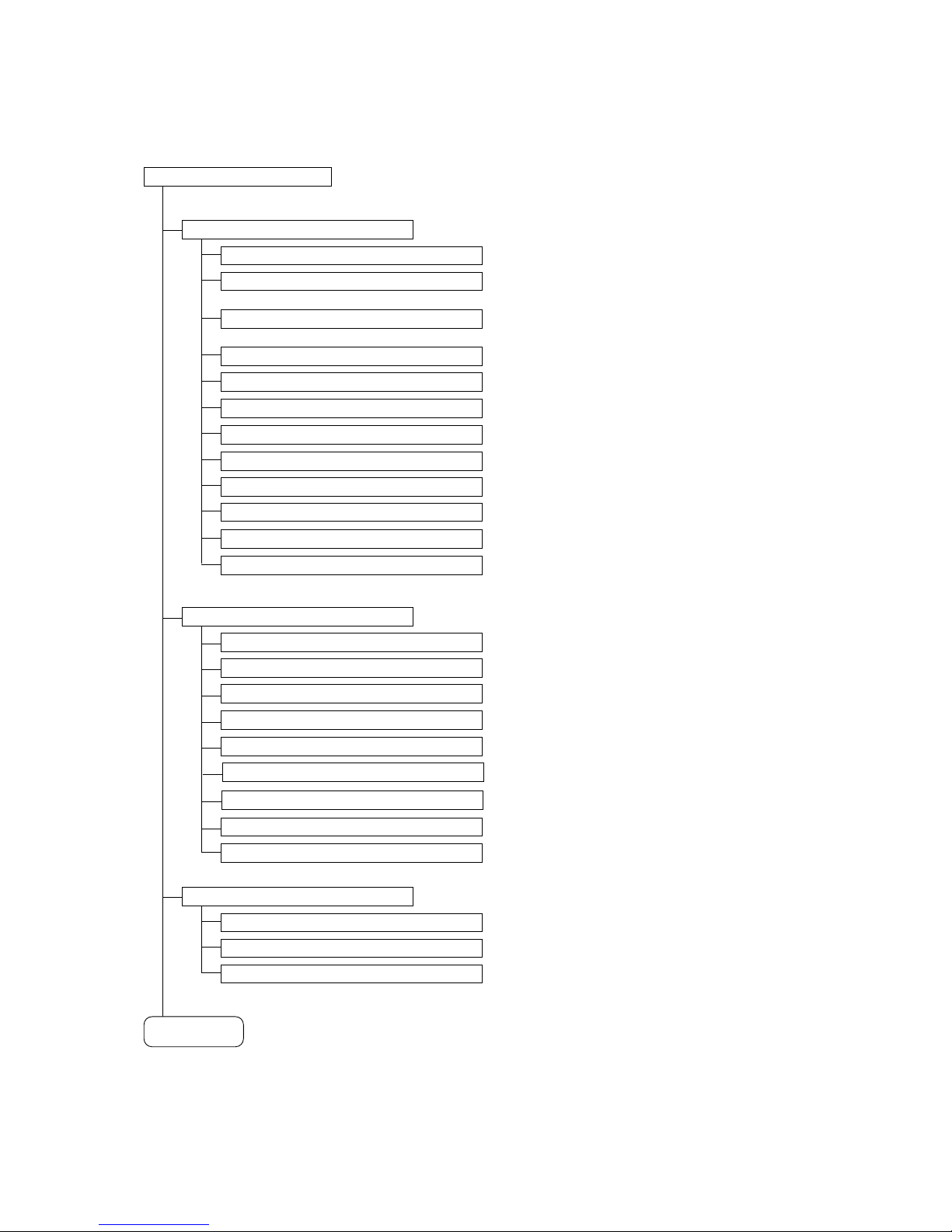
1. SETTING ITEMS GUIDE
The camera menu screens are comprised of the following setting item screens.
Corrects the position displacement.
Corrects stepping motor displacement.
Selects language.
Permits password setting.
Sets the password parameters.
Turns the display of each ID on or off.
Displays system status.
Deletes all function settings simultaneously.
Adjusts the camera's brightness.
Sets the shutter speed.
Adjusts the chroma.
Sets the contour enhancement function.
Sets the Electronic zoom.
Sets the camera's white balance.
Sets the backlight compensation.
Sets the slow shutter.
Sets the automatic gain control (AGC).
Displays the desired preset No.
Sets the preset ID.
Sets the position to be programmed.
Page 5

5
From previous
page
AUTO PAN ID
(
p. 28
)
START ANGLE
(
p. 28
)
END ANGLE
(
p. 28
)
DIRECTION
(
p. 28
)
PAUSE TIME
(
p. 29
)
AUTO PAN
(
p. 27
)
TOUR
(
p. 30
)
PRIVACY MASK
(
p. 33
)
TRACE
(
p. 36
)
ALARM
(
p. 39
)
ENDLESS
(
p. 29
)
SPEED
(
p. 29
)
TOUR STEP
(
p. 31
)
PRESET NO.
(
p. 31
)
PAUSE TIME
(
p. 31
)
SPEED
(
p. 31
)
TOUR NO.
(
p. 31
)
TOUR ID
(
p. 32
)
PRIVACY NO.
(
p. 34
)
DISPLAY
(
p. 34
)
TRACE NO.
(
p. 37
)
TRACE ID
(
p. 38
)
EVENT FILL
(
p. 37
)
ALARM NO.
(
p. 40
)
INPUT
(
p. 40
)
ACTION
(
p. 40
)
ACTION
(
p. 34
)
SECTOR
(
p. 41
)
SECTOR START
(
p. 42
)
SECTOR END
(
p. 42
)
SECTOR NO.
(
p. 42
)
SECTOR ID
(
p. 43
)
Sets the Auto-Pan ID.
Sets the start point.
Sets the end point.
Sets the rotation direction.
Sets to enable or disable the limit.
Sets the Auto-Pan speed.
Sets the Auto-Pan pause duration.
Displays the desired Tour No.
Sets the tour ID.
Displays the tour operation No.
Sets the preset No. to be programmed.
Sets the pause duration between the steps.
Sets the preset speed between the steps.
Displays the desired privacy mask No.
Turns the display of the mask on and off.
Sets the masking location and size.
Displays the desired trace No.
Sets the trace ID.
Stores trace operation in memory.
Displays the desired alarm No.
Sets the input status of the alarm signal.
Sets the camera operation when the alarm signal is
received.
Displays the desired sector No.
Sets the sector ID.
Sets the sector start position.
Sets the sector end position.
Page 6

6
PROTOCOL : T YPE-B
CAMERA I D : 0 0 1
BAUD RA T E : 3 8 4 0 0 BPS
PAN OR I G I N CHECK OK
TILT ORIGIN CHECK OK
TX CONNECT I ON TEST 57
CAMERA COMM TE ST
987
654
21
FOCUS
IRIS
REMOTE CONTROLLER C-RM700
WIDE TELE
F8F7F6F5F4F3F2F1
MENUCH
ALARM
HOLDRESET
WIPER AUX1 AUX2 AUTO
FREEZE
CONTROL
POSITION
CAMERA
AF
LENS SPEED
3
0
SET
C
GROUP
SELECT
SEQUENCE
Joystick
Clear key
Focus key
Set key
Numeric keypad
Menu key
Iris key
Auto focus key
Lens speed key
2. BEFORE SETTING
2.1. About Address Display When Turning Power On
When the camera's power is turned on, the camera performs the
initial operation (initializing operation). Simultaneously, the
camera address screen, which displays the communication
protocol, camera address, and baud rate, appears on the
monitor. After the completion of the initial operation and
peripheral device connections, the camera can be controlled and
the camera address screen will disappear. Then, motor operation
is checked, and the initial screen will disappear.
Note
TX CONNECTION TEST is a check item to see if the camera
communicates with the controller.
The result "NG" is displayed in case of no connection or
misconnection between the camera and the controller. There is
no problem even if "NG" is displayed as long as the camera
begins control with the controller after the completion of the initial
operation (initializing operation).
2.2. Keys Used for Setting
Use the equipment which controls the camera or the remote controller connected to such equipment to
perform camera settings.
Use the joystick and each key on the C-RM700's top panel.
[
C-RM700's top
]
When the dedicated Remote Controller C-RM700 is connected
Page 7

7
2.3. Basic Setting Operation
Menu screen display and some operations differ slightly depending on the equipment to be connected, but
basic setting operations are the same for such equipment.
Explanation is given in reference to screens below. (The shaded rectangle shows the cursor position.
)
For details, refer to the instruction manual, operation manual, or setup manual enclosed with each equipment.
• Menu key
Use this key to enter or exit the menu screen.
[
When the dedicated C-RM700 Remote Controller is connected
]
Pressing the Menu key always terminates the menu screen regardless of any setting screen display.
• Joystick (Tilt up, down, left, and right.
)
Tilting the joystick up or down moves the cursor position to select functions.
Tilting the joystick left or right changes the setting item.
Use the joystick when performing Preset Memory and Auto Operation settings or panning the camera.
• Set key
Changes the camera to pan mode.
• Clear key
Cancels password setting or deletes numbers entered incorrectly.
• Numeric keypad
Used to enter the camera number, position number, or password.
• Joystick (Pan
)
Used to perform Preset Memory, zoom operation, or ID settings.
• Focus key
Used to perform Preset Memory or focus operation settings.
Page 8

8
C-RM700
Menu screen display
Menu screen exit
Function selection
Setting item selection
Setting item confirmation
Number clearing
Camera No. input
Position input
Manual operation
Menu key
Tilting the joystick up or down
Tilting the joystick left or right
Tilting the joystick left or right
Set key
Clear key
Numeric keypad
Joystick
(
Tilting up, down, left, right, and rotating.
)
Focus key
2.4. Operation Method
The following table shows the principal key operations for the Remote Controller to be connected.
Page 9
9
MA I N M EN U
DOME S E TU P
CAMERA S ET
PRESET
AUTO PAN
TOUR
PR I VACY MASK
TRACE
ALARM
SECTOR
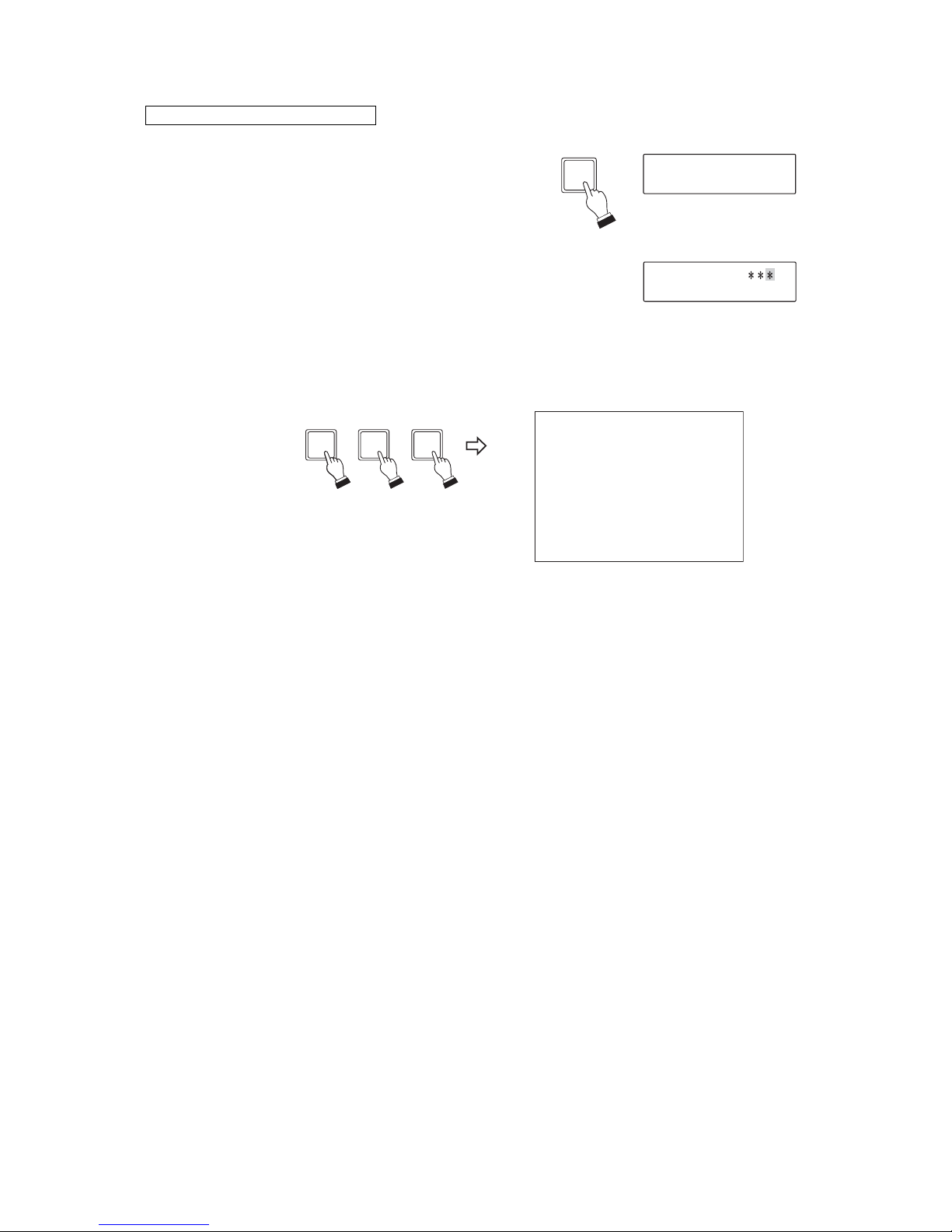
3. ENTERING THE CAMERA MENU SCREEN
1. Press the Menu key. (Enter the password with the
numeric key pad if required.)
The menu screen is displayed on the dedicated Remote
Controller's LCD.
2. Select "CAMERA MENU" with the joystick, then press
the Set key.
The screen changes to ask for the camera number input
to open the camera menu.
3. Enter the desired camera number with the numeric key
pad, then press the Set key to confirm the number.
The main menu screen for the selected camera is
displayed on the monitor.
When the C-RM700 is connected
4. Select the desired item with the joystick, then perform setting on each setting screen.
OPERAT I ON MODE
CAMERA ME NU CH
21
SET
(Example)
MENU
Page 10
10
DOME SE T
C A M E R A I D : C A M 0 1
AUTO RE TURN : OF F
H O M E : 1 P O S
MAX P / T S P D : 1 0 0 ° / S
REFRESH : OFF
INITIALIZE :OFF
LANGU AGE : ENG L I SH
[
NEXT PAGE
]
SAVE AND EX I T
EX I T
C
AMERAID
C
DOME SE T
C A M E R A I D : C A M 0 1
AUTO RE TURN : OF F
H O M E : 1 P O S
MAX P /T SPD : 100° /S
REFRESH : OFF
INITIALIZE :OFF
LANGU AGE : ENG L I SH
[
NEXT PAGE
]
SAVE AND EX I T
EX I T
[
NEXTP
AGE
]
DOME SE T
C A M E R A I D : C A M 0 1
AUTO RE TURN : OF F
H O M E : 1 P O S
MAX P / T S P D : 1 0 0 ° / S
REFRESH : OFF
INITIALIZE :OFF
LANGU AGE : ENG L I SH
[
NEXT PAGE
]
SAVE AND EX I T
EX I T
S
DOME SE T
C A M E R A I D : C A M 0 1
AUTO RE TURN : OF F
H O M E : 1 P O S
MAX P / T S P D : 1 0 0 ° / S
REFRESH : OFF
INITIALIZE :OFF
LANGU AGE : ENG L I SH
[
NEXT PAGE
]
SAVE AND EX I T
EX I T
DOME SE T
SYSTEM LOCK :OF F
[
PASSWORD
]
[
OSD D I S PL AY
]
[
SYSTEM STATUS
]
[
CLEAR
]
[
PREV I OUS PAGE
]
[
O
USG
]
Save changes and exit Exit
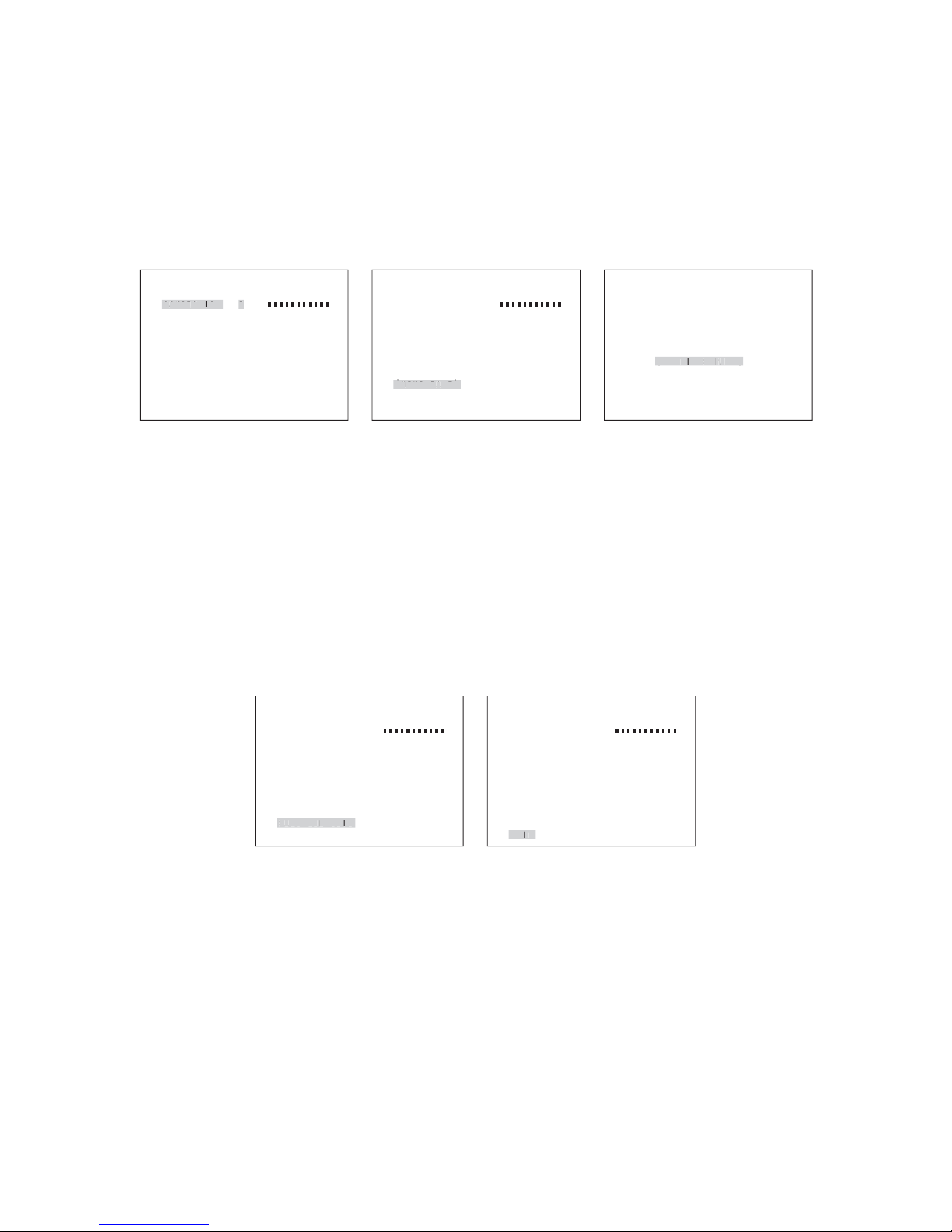
4. DOME SETTING
4.1. Displaying the Dome Setting Screen
Tilt the joystick up or down to select the "DOME SETUP" on the main menu screen, then tilt the joystick right.
Dome setting screen is displayed.
To display the next page, tilt the joystick up or down to select "NEXT PAGE," then tilt the joystick right.
To display the previous page, tilt the joystick up or down to select "PREVIOUS PAGE," then tilt the joystick
right.
Dome setting
Next page
Previous page
4.2. Exiting the Setting
Save changes and exit:
Tilt the joystick up or down to select the "SAVE AND EXIT" on the dome setting screen, then tilt the joystick
right.
This saves the setting, and the display returns to the main menu screen.
Exit and lose changes:
Tilt the joystick up or down to select the "EXIT" on the dome setting screen, then tilt the joystick right.
This cancels changes and the display returns to the main menu screen.
Page 11

11
DOME SE T
C A M E R A I D : C A M 0 1
AUTO RE TURN : OF F
H O M E : 1 P O S
MAX P / T S P D : 1 0 0 ° / S
REFRESH : OFF
INITIALIZE :OFF
LANGU AGE : ENGL I S H
[
NEXT PAGE
]
SAVE AND EX I T
EX I T
AUTORETUR
N
DOME SE T
C A M E R A I D : C A M 0 1
AUTO RE TURN : OF F
H O M E : 1 P O S
MAX P / T S P D : 1 0 0 ° / S
REFRESH : OFF
INITIALIZE :OFF
LANGU AGE : ENGL I S H
[
NEXT PAGE
]
SAVE AND EX I T
EX I T
C
C
4.3. Setting the Camera ID
1. Tilt the joystick up or down to select the "CAMERA ID" on the
dome setting screen.
2. Enter the Camera ID.
Selection: Tilt the joystick left or right to select the character.
Move: Rotating the joystick clockwise (TELE) moves the
cursor one character to the right.
Rotating the joystick counterclockwise (WIDE) moves
the cursor one character to the left.
Note
The black square symbol in the screen shows a space.
"Character Table" on p. 46 shows usable characters for ID values.
4.4. Setting the Auto Return
This function is used to determine operation when the camera is not controlled at all. The camera
automatically reverts to the initially set operation (Home) when the preset period of time elapses after the
controller's control has been finished.
1. Tilt the joystick up or down to select the "AUTO RETURN" on the
dome setting screen.
2. Select "OFF," or "15" through "90" (5-second intervals) by tilting
the joystick left or right.
An interval till the Auto Return function is operated is set or the
function is disabled (OFF).
Note
This function operates independently of the C-RM700's Auto Return
function.
When Alarm Hold function is required, use the C-RM700's Auto
Return function.
Page 12

12
DOME SE T
C A M E R A I D : C A M 0 1
AUTO RE TURN : OF F
H O M E : 1 P O S
MAX P / T S P D : 1 0 0 ° / S
REFRESH : OFF
INITIALIZE :OFF
LANGU AGE : ENGL I S H
[
NEXT PAGE
]
SAVE AND EX I T
EX I T
HOM
E
DOME SE T
C A M E R A I D : C A M 0 1
AUTO RE TURN : OF F
H O M E : 1 P O S
MAX P / T S P D : 1 0 0 ° / S
REFRESH : OFF
INITIALIZE :OFF
LANGU AGE : ENGL I S H
[
NEXT PAGE
]
SAVE AND EX I T
EX I T
MAXP/
TSP
D
4.5. Setting Home
Determines the operation when the Auto Return is activated.
1. Tilt the joystick up or down to select "HOME" on the dome setting
screen.
2. Select "1 POS," "2 POS," "AUTO PAN," "TRACE 1" through
"TRACE 8," or "TOUR 1" through "TOUR 8" by tilting the joystick
left or right.
The operation at the Auto Return activation is set.
Note
The camera will not operate even if the item not stored is selected.
4.6. Setting Manual Speed (Type A only)
Sets the maximum speed of pan and tilt in manual operation.
1. Tilt the joystick up or down to select "MAX P/T SPD" on the dome
setting screen.
2. Select "100˚/S" through "150˚/S" by tilting the joystick left or right.
The maximum speed at a wide angle limit in manual operation is
confirmed.
Note: The larger the figure is, the faster the speed.
Page 13
13
DOME SE T
C A M E R A I D : C A M 0 1
AUTO RE TURN : OF F
H O M E : 1 P O S
MAX P / T S P D : 1 0 0 ° / S
REFRESH : OFF
INITIALIZE :OFF
LANGU AGE : ENGL I S H
[
NEXT PAGE
]
SAVE AND EX I T
EX I T
REFRESH
02 / 02
Indicates the time until the next
refresh operation starts.
Sets the time duration till the refresh
operation starts from the clock time
of setting completion.
4.7. Setting Refresh
If the camera with its power continuously kept on is used for long periods of time, the camera position may
deviate when the preset position is played back. In such cases, deviation can be corrected using the Autorefresh function. Also, if the camera's horizontal rotation contacts get dirty, the displayed image may become
distorted when the camera pans or manual operation interrupted. To prevent these troubles, using the Autorefresh function is recommended to clean horizontal rotation contacts periodically.
"OFF" : Not refreshed.
"00/24," "01/01" through "23/23" (one-hour intervals) :
Daily refresh operation can be set.
For example, when setting "02/02" on Sunday at 10:00 am, the first refresh operation starts at 00:00 pm,
2 hour later after setting, and the refresh function operates at 00:00 pm everyday afterward.
Notes
• The interval (one-day) for the refresh operation will deviate when the camera is used for extended period of
time. If the time deviation is annoying, perform the setting for the refresh start time again.
• If the camera's power is shut off after performing the refresh operation setting, the refresh setting turns OFF.
For example, the refresh setting is returned to OFF state at the time of the power failure. In such cases,
perform the setting again.
1. Tilt the joystick up or down to select "REFRESH" on the dome
setting screen.
2. Select "OFF," "00/24," or "01/01" through "23/23" by tilting the
joystick left or right.
Page 14
14
DOME SE T
C A M E R A I D : C A M 0 1
AUTO RE TURN : OF F
H O M E : 1 P O S
MAX P / T S P D : 1 0 0 ° / S
REFRESH : OFF
INITIALIZE :OFF
LANGU AGE : ENGL I S H
[
NEXT PAGE
]
SAVE AND EX I T
EX I T
GUG
DOME SE T
C A M E R A I D : C A M 0 1
AUTO RE TURN : OF F
H O M E : 1 P O S
MAX P / T S P D : 1 0 0 ° / S
REFRESH : OFF
INITIALIZE :OFF
LANGU AGE : ENGL I S H
[
NEXT PAGE
]
SAVE AND EX I T
EX I T
INITIALIZ
E
4.8. Initializing
In the combination camera's preset memory playback function, a stepping motor is operated by open loop
control. Therefore, if the camera is used for long uninterrupted periods of time, the camera position may
deviate from the original settings. In such cases, deviation can be corrected with re-initialization.
Note: Set data are not erased by initializing operation.
1. Tilt the joystick up or down to select "INITIALIZE" on the dome
setting screen.
2. Select "ON" by tilting the joystick left or right.
3. As "ARE YOU SURE?" is displayed, select "YES," then press the
Set key.
Initialization is started.
Note
Pressing the Set key after selecting "NO" returns the display to the
dome setting screen.
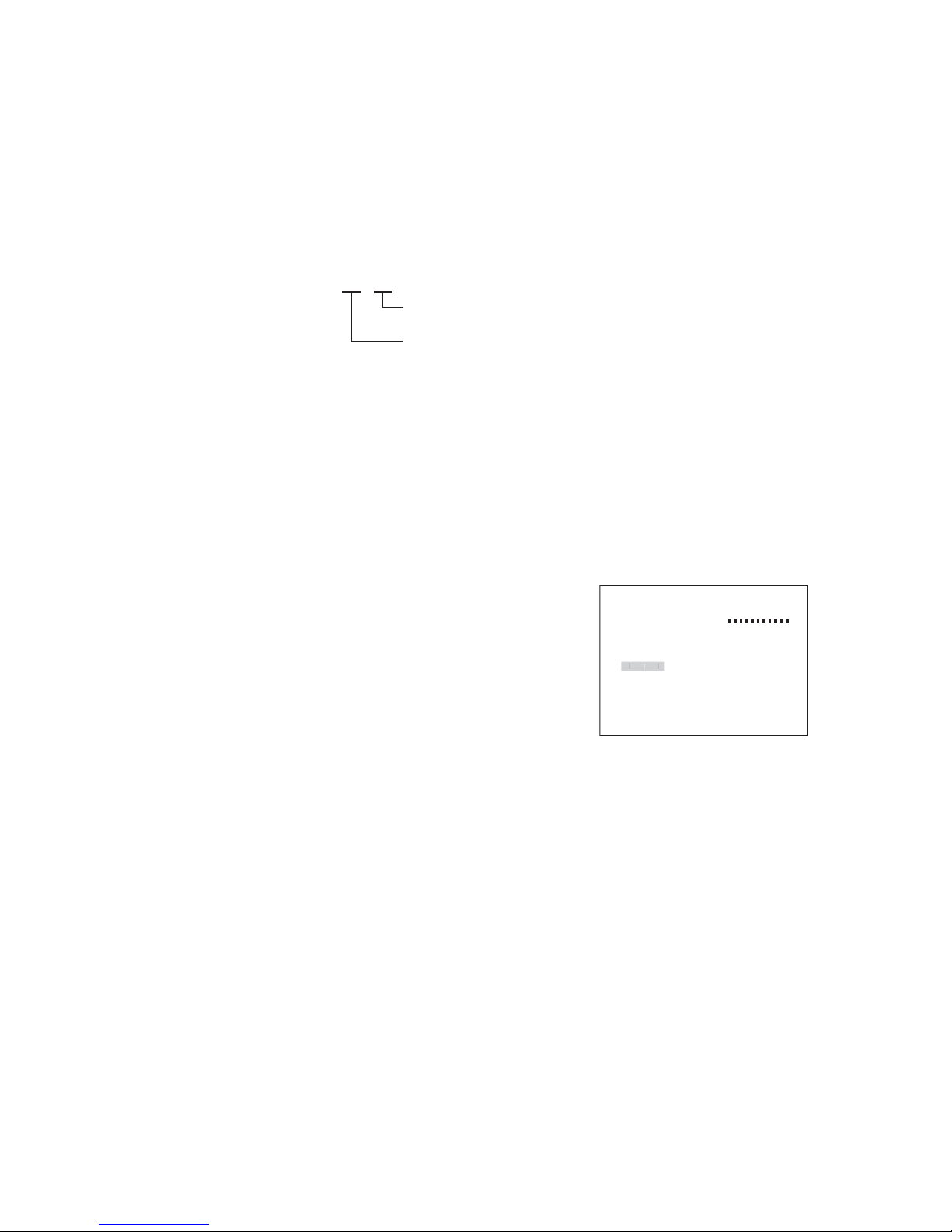
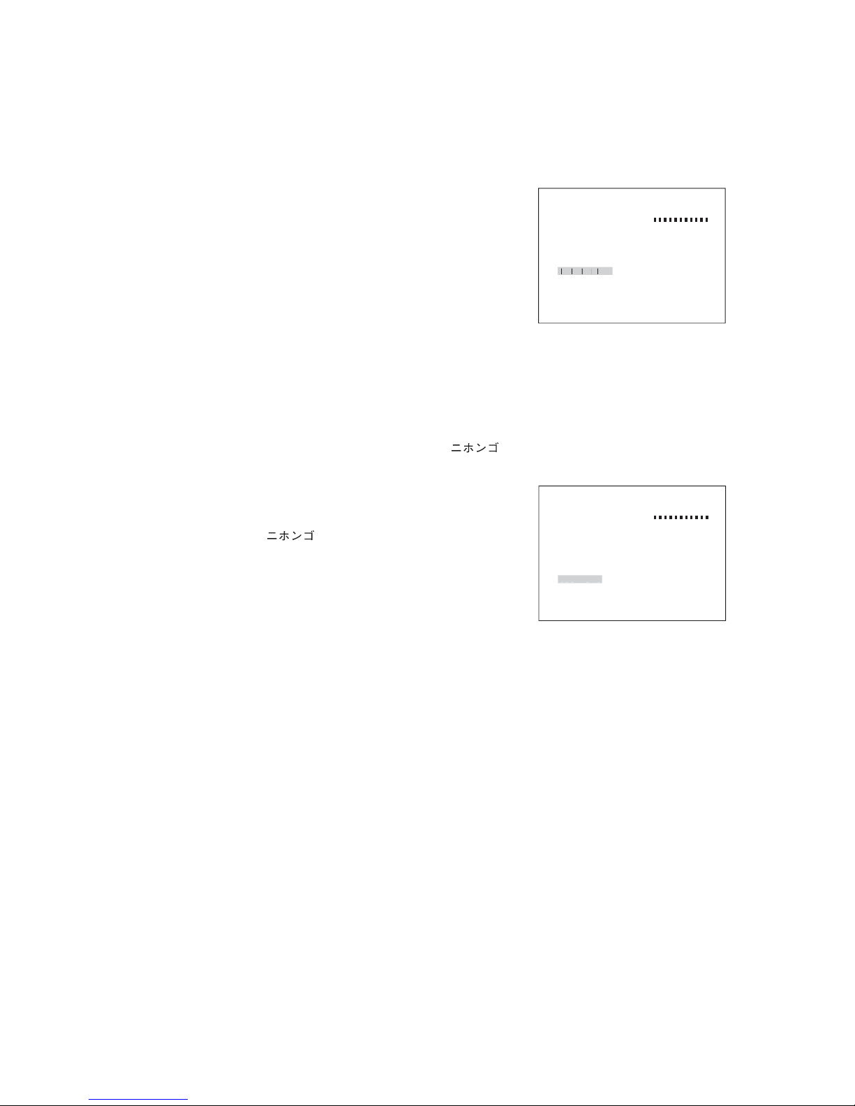
4.9. Setting Language
Language indication can be selected either "ENGLISH" or " " on the menu screen.
1. Tilt the joystick up or down to select "LANGUAGE" on the dome
setting screen.
2. Select "ENGLISH" or " " by tilting the joystick left or right.
Page 15

15
ENTER PASSWORD
BY ENTER I NG PRE SET CODE !
PASSWORD
CONF I RM
DOME SE T
SYSTEM LOCK :ON
[
PASSWORD
]
[
OSD D I S PL AY
]
[
SYSTEM STATUS
]
[
CLEAR
]
[
PREV I OUS PAGE
]
SYS
TEM
L
O
C
K
DOME SE T
SYSTEM LOCK :ON
[
PASSWORD
]
[
OSD D I S PL AY
]
[
SYSTEM STATUS
]
[
CLEAR
]
[
PREV I OUS PAGE
]
[
P
A
S
S
WOR
D
]
4. 10. Setting the Password
Set the password required when activating the Camera menu screen.
ON: Displays the Password entry screen when entering the menu screen.
Password can be set.
OFF: Allows to enter the maintenance screen without password verification.
Password cannot be set.
1. Tilt the joystick up or down to select "SYSTEM LOCK" on the
dome setting screen.
2. Select "ON" by tilting the joystick left or right.
3. Tilt the joystick up or down to select "PASSWORD," then tilt the
joystick right.
Password setting screen is displayed.
Note: It is not possible to enter "PASSWORD" without selecting
"ON" for the system lock in Step 2.
4. Enter 3-digit password in the "PASSWORD" field.
Press the Set key each time when a digit is entered.
5. Enter the same password again in the "CONFIRM" filed.
When the setting has been performed correctly, "OK!" is
displayed.
Note
When the password has not been entered correctly, "FAIL!" is
displayed.
It means that password has not been set. In such cases, enter the
password again.
Page 16

16
OSD D I S PL AY
CAMERA : OF F
PRESET I D : OFF
AUTO PAN I D : OFF
TOUR I D : OF F
TRACE I D :OFF
SECTOR I D :OF F
ADDRES S / ANGL E : OFF
LOCAT I ON : 1
[
PREV I OUS PAGE
]
C
AMERA
CAMERA I D
PRESET
AUTOPAN
CAM I D: 001
XXX . X XX . X
CAM I D: 001
XXX . X XX . X
CAMERA I D
PRESET
AUTOPAN
DOME SE T
SYSTEM LOCK :ON
[
PASSWORD
]
[
OSD D I S PL AY
]
[
SYSTEM STATUS
]
[
CLEAR
]
[
PREV I OUS PAGE
]
[
O
S
DDISPLA
Y
]
Setting item
Setting content
Displays the camera title.
*1
CAMERA ID
Displays the preset title (1 - 64).
*1
PRESET ID
Displays the trace title (1 - 8).
*1
TRACE ID
*1
Maximum character length is 16 characters.
Displays the auto-pan title.
*1
AUTO PAN ID
Displays the tour title (1 - 8).
*1
TOUR ID
Displays the sector title (1 - 8).
*1
SECTOR ID
Displays the coordinate. Displays the coordinates showing the pan (0° to 359°) and
tilt (+2° to
-
90°) angles.
ADDRESS / ANGLE
Display position can be selected from 2 patters.
LOCATION
Display location 1 Display location 2
4.11. Setting Display Content
Contents to be displayed can be set by selecting "OSD DISPLAY" on the dome setting screen.
1. Tilt the joystick up or down to select "OSD DISPLAY" on the
dome setting screen, then tilt the joystick right.
OSD indication setting screen is displayed.
2. Tilt the joystick up or down to select the item to be changed.
3. Select "OFF" or "ON" (Select "1" or "2" for the LOCATION) by
tilting the joystick left or right:
OFF: Nothing is displayed.
ON: Every IDs are all displayed.
"1" or "2" : Changes the display position of each individual ID.
Page 17

17
DOME SE T
SYSTEM LOCK :ON
[
PASSWORD
]
[
OSD D I S PL AY
]
[
SYSTEM STATUS
]
[
CLEAR
]
[
PREV I OUS PAGE
]
[
SSSUS
]
SYSTEM STATUS
PROTOCOL : T YPE
-
A
BAUD RA T E : 3 8 4 0 0 BP S
CAMERA : M
-
NTSC
230a28H08
26H08
[
PREV I OUS PAGE
]
[
O
USG
]
DOME SE T
SYSTEM LOCK :ON
[
PASSWORD
]
[
OSD D I S PL AY
]
[
SYSTEM STATUS
]
[
CLEAR
]
[
PREV I OUS PAGE
]
[C]
CLEAR
[
CAMERA S ET CL EAR
]
[
TOUR CLEAR
]
[
PRESET CLEAR
]
[
SECTOR CLEAR
]
[
PR I VACY CL EAR
]
[
TRACE CLEAR
]
[
FACTORY PRESET
]
[
PREV I OUS PAGE
]
[
C
AMERASE
TCLEA
R
]
CAMERA S ET CLEAR
ARE YOU SURE ? YES NO
Example: Deleting the Camera setting
4.12. Confirming System Settings
The current protocol, communication speed (baud rate), and camera information can be checked.
1. Tilt the joystick up or down to select "SYSTEM STATUS" on the
dome setting screen, then tilt the joystick right.
System setting screen is displayed.
PROTOCOL : Indicates the RS-485 communication method.
BAUD RATE : Indicates the camera communication speed.
CAMERA : For maintenance.
4.13. Deleting the Settings
Used when returning the settings to their initial factory defaults.
1. Tilt the joystick up or down to select "CLEAR" on the dome setting
screen, then tilt the joystick right.
Setting deletion screen is displayed.
2. Tilt the joystick up or down to select the item to be deleted on the
setting deletion screen, then tilt the joystick right.
3. As "ARE YOU SURE?" is displayed, select "YES," then press the
Set key.
The deletion screen is displayed, then the screen display
disappears when the deletion is completed.
Page 18

18
CAMERA S ET
BR I GHTNE SS : 5
SHUTT ER SPEED : NORMA L
CHROMA : 5
ENHANCER : 5
E
-
ZOOM : ON
WHI T E BA LANCE : A TW
BACKL I GH T : OF F
SLOW SHUTTER : 64
AGC : AU T O
EX I T
BRIGHTN
E
SS5
Camera setting
Exit
CAMERA S ET
BR I GHTNE SS : 5
SHUTT ER SPEED : NORMA L
CHROMA : 5
ENHANCER : 5
E
-
ZOOM : ON
WHI T E BA LANCE : A TW
BACKL I GH T : OF F
SLOW SHUTTER : 64
AGC : AU T O
EX I T
EXI
T
5. CAMERA SETTINGS
5.1. Displaying the Camera Setting Screen
Tilt the joystick up or down to select "CAMERA SET" on the main menu screen, then tilt the joystick right.
Camera setting screen is displayed.
5.2. Exiting the Camera Setting Screen
Tilt the joystick up or down to select "EXIT" on the camera setting screen, then tilt the joystick right. The
screen returns to the main menu screen.
Page 19

5.3. Auto Focus
The auto focus operates in "STOP AF" mode.
STOP AF: Auto-focusing is automatically operated after the camera scene or angle of view has been
changed. The "STOP AF" mode does not work when the Focus key is used. Pressing the Autofocus key again returns the camera in the STOP AF mode.
Notes
Under the following conditions, a subject may go out of focus if the auto focus function is used:
• When a part of the subject shines especially bright.
• When the distant and near subjects exist together.
• When the camera shoots a blind or other subject with horizontal stripes.
• When the subject's lighting conditions are poor.
• When the camera rotates at high speed.
19
CAMERA S ET
BRI GHTNESS : 5
SHUTTER SPEED : NORMAL
CHROMA : 5
ENHANCER : 5
E
-
ZOOM : ON
WH I TE B A L AN C E : ATW
BACKL I GH T : OF F
SLOW SHUTTER : 64
AGC : AU T O
EX I T
BRIGHTN
E
SS5
5.4. Adjusting Brightness
The camera's brightness can be adjusted to suit user preferences.
1. Tilt the joystick up or down to select "BRIGHTNESS" on the
camera setting screen.
2. Select from "1" through "9" by tiling the joystick left or right.
The Brightness setting is confirmed.
Note: The larger the number value, the brighter the image.
Page 20

20
CAMERA S ET
BR I GHTNE SS : 5
SHUTT ER SPEED : NORMA L
CHROMA : 5
ENHANCER : 5
E
-
ZOOM : ON
WH I TE B A L AN C E : ATW
BACKL I GH T : OF F
SLOW SHUTTER : 64
AGC : AU T O
EX I T
SHU
TTE
RSPEE
D
CAMERA S ET
BRI GHTNESS : 5
SHUTTER SPEED : NORMAL
CHROMA : 5
ENHANCER : 5
E
-
ZOOM : ON
WH I TE B A L AN C E : ATW
BACKL I GHT :OF F
SLOW SHUTTER : 64
AGC : AU T O
EX I T
C
H
ROM
A
5.5. Setting Shutter Speed
Fixed shutter speed can be selected.
Select "NORMAL," "1/100," "1/120," "1/250," "1/500," "1/1000," "1/2000," "1/4000," or "1/10000."
Notes
• If shutter speed other than "NORMAL" is selected, the Slow Shutter function (Refer to p. 23) cannot be used.
• Avoid selecting shutter speed of 1/100 for the purposes of reducing flicker as the unit is performing automatic
flicker reduction control*.
* Operation to reduce screen flickering that may occur when a subject is shot by a camera under fluorescent
lighting in area where power frequency is 50 Hz.
Note: Usually use "NORMAL" setting.
1. Tilt the joystick up or down to select "SHUTTER SPEED" on the
camera setting screen.
2. Select "NORMAL," "1/100," "1/120," "1/250," "1/500," "1/1000,"
"1/2000," "1/4000," or "1/10000" by tilting the joystick left or right.
The selected content is confirmed.
5.6. Setting the Chroma
The chroma may be adjusted to suit user preferences.
1. Tilt the joystick up or down to select "CHROMA" on the camera
setting screen.
2. Select from "1" through "9" by tiling the joystick left or right.
The chroma setting is confirmed.
Note: The larger the number value, the darker the color.
Page 21

21
CAMERA S ET
BR I GHTNE SS : 5
SHUTT ER SPEED : NORMA L
CHROMA : 5
ENHANCER : 5
E
-
ZOOM : ON
WH I TE B A L AN C E : ATW
BACKL I GH T : OF F
SLOW SHUTTER : 64
AGC : AU T O
EX I T
C
CAMERA S ET
BR I GHTNE SS : 5
SHUTT ER SPEED : NORMA L
CHROMA : 5
ENHANCER : 5
E
-
ZOOM : ON
WH I TE B A L AN C E : ATW
BACKL I GH T : OF F
SLOW SHUTTER : 64
AGC : AU T O
EX I T
O
O
5.7. Setting the Enhancer Function
This function emphasizes the contours of the image. The degree of emphasis can be adjusted to suit user
requirements.
1. Tilt the joystick up or down to select "ENHANCER" on the camera
setting screen.
2. Select from "1" through "9" by tiling the joystick left or right.
The enhancer setting is confirmed.
Note
As the number becomes larger, the contour enhancement
increases.
5.8. Setting Electronic Zoom
Use the Electronic zoom*2function to get a close-up picture more than is possible using the optical zoom *1.
It is possible to set the Electronic zoom function to turn "ON" or "OFF."
ON: Turns on the Electronic zoom function.
OFF: Turns off the Electronic zoom function.
*1
The zoom function through an optical lens.
*2
Zoom function which uses the scanning variation or image memory of the image pickup sensor instead of an
optical lens to electronically magnify or reduce the image. Images will become coarser as the degree of
Electronic zoom increases.
1. Tilt the joystick up or down to select "E-ZOOM" on the camera
setting screen.
2. Select "ON" or "OFF" by Tilting the joystick left or right.
The Electronic zoom function is confirmed.
Page 22

22
CAMERA S ET
BR I GHTNE SS : 5
SHUTT ER SPEED : NORMA L
CHROMA : 5
ENHANCER : 5
E
-
ZOOM : ON
WH I TE BALANCE : ATW
BACKL I GH T : OF F
SLOW SHUTTER : 64
AGC : AU T O
EX I T
C
CAMERA S ET
BR I GHTNE SS : 5
SHUTT ER SPEED : NORMA L
CHROMA : 5
ENHANCER : 5
E
-
ZOOM : ON
WH I TE B A L AN C E : ATW
BACKL I GH T : OF F
SLOW SHUTTER : 64
AGC : AU T O
EX I T
C
G
5.9. Setting White Balance
Four modes are made available for white balance: "ATW," "AWB," "ATW-R," and "ATW-B."
ATW: The camera's white balance varies with the change in color temperature of the subject's light source.
AWB: The camera's white balance is fixed even if the color temperature of the subject's light source
changes.
ATW-R: Fine-adjusts the color temperature at lower setting relative to ATW. (Red)
ATW-B: Fine-adjusts the color temperature at higher setting relative to ATW. (Blue)
Note: ATW will not function when the high sensitivity slow shutter function is in use.
1. Tilt the joystick up or down to select "WHITE BALANCE" on the
camera setting screen.
2. Select "ATW," "AWB," "ATW-R," or "ATW-B" by tilting the joystick
left or right.
White balance setting is confirmed.
5.10. Setting Backlight Compensation
This function makes the subjects more clearly visible under strong backlight condition.
Select either "OFF" or "ON."
OFF: Turns off the backlight compensation function. Select OFF in normal use.
ON: Select ON in backlight condition.
1. Tilt the joystick up or down to select "BACKLIGHT" on the camera
setting screen.
2. Select "OFF" or "ON" by tilting the joystick left or right.
Page 23

23
CAMERA S ET
BR I GHTNE SS : 5
SHUTT ER SPEED : NORMA L
CHROMA : 5
ENHANCER : 5
E
-
ZOOM : ON
WH I TE B A L AN C E : ATW
BACKL I GH T : OF F
SLOW SHUTTER : 64
AGC : AU T O
EX I T
A
G
C
CAMERA S ET
BR I GHTNE SS : 5
SHUTT ER SPEED : NORMA L
CHROMA : 5
ENHANCER : 5
E
-
ZOOM : ON
WH I TE B A L AN C E : ATW
BACKL I GH T : OF F
SLOW SHUTTER : 64
AGC : AU T O
EX I T
S
LOWSHUTTE
R
5.11. Setting High-Sensitivity Slow Shutter
Depending on the subject's brightness level, the camera is automatically put in slow shutter mode, the limit of
which can be set by selecting from "OFF," "02," "04," "08," "16," "32," and "64." The slow shutter function
cannot be used when "OFF" is selected.
1. Tilt the joystick up or down to select "SLOW SHUTTER" on the
camera setting screen.
2. Select "OFF," "02," "04," "08," "16," "32," or "64" by tilting the
joystick left or right.
The selected content is confirmed.
5.12. Setting AGC
The AGC function can be set for "AUTO," "OFF," or "MAX."
AUTO: Automatically adjusts the gain depending on the subject's brightness level.
OFF: Disables the automatic gain control function.
MAX: Used when the subject brightness is insufficient when in AUTO mode.
Note
Operation in "MAX" mode may cause excessive vertical noise, however this is not a failure. If it becomes
annoying, select "AUTO" mode.
1. Tilt the joystick up or down to select "AGC" on the camera setting
screen.
2. Select "AUTO," "OFF," or "MAX" by tilting the joy stick left or right.
The AGC setting is confirmed.
Page 24

24
PRESET SET
PRESET NO. : 0 01
PRESET I D : PRESET 0 01
PAN : 00 0 T I LT :
-
26
SAVE
CLEAR
EX I T
PRESETNO.
Preset
Exit
PRESET SET
PRESET NO. : 0 01
PRESET I D : PRESET 0 01
PAN : 00 0 T I LT :
-
26
SAVE
CLEAR
EX I T
6. PRESET
Specific camera scenes, lens view angles, and lens focuses can be preset in advance. Up to 64 preset
positions can be set.
6.1. Displaying the Preset Setting Screen
Tilt the joystick up or down to select "PRESET" on the main menu screen, then tilt the joystick right. The
preset setting screen is displayed.
6.2. Exiting the Preset Setting Screen
Tilt the joystick up or down to select "EXIT" on the preset setting screen, then tilt the joystick right. The screen
returns to the main menu screen.
Page 25

25
PRESET SET
PRESET NO . : 00 1
PRESET I D : PRE SET 0 0 1
PAN : 00 0 T I LT :
-
26
SAVE
CLEAR
EX I T
PRESETNO.
PRESET SE T
PRESET NO. : 0 01
PRESET I D : PRESET 0 01
PAN : 00 0 T I LT :
-
26
SAVE
CLEAR
EX I T
PANTILT
6.3. Storing Preset
It is not possible to preset positions in the Electronic zoom areas (refer to p. 21). Presetting is possible only for
areas not included in the Electronic zoom range .
1. Tilt the joystick up or down to select "PRESET NO." on the preset
setting screen.
2. Select the desired preset No. from "001" through "064" by tilting
the joystick left or right.
Pressing the Set key moves the cursor to the preset position.
3. Tile the joystick up or down to select "PAN: *** TILT: ***," then
press the Set key.
" " appears on the left side of "PAN: *** TILT: ***", permitting
manual operation.
4. Using the joystick (Pan and Zoom) and Focus keys, move the
camera direction to the desired position, then press the Set key.
" " on the left side of "PAN: *** TILT: ***" disappears.
5. Tilt the joystick up or down to select "SAVE," then tilt the joystick
right.
The preset position of the selected preset No. is stored.
Preset No. automatically moves to the next preset No.
Page 26

26
PRESET SET
PRESET NO. : 0 01
PRESET I D : PRESET 0 01
PAN : 00 0 T I LT :
-
26
SAVE
CLEAR
EX I T
PRESETIDP
PRESET SET
PRESET NO. : 0 01
PRESET I D : PRESET 0 01
PAN : 00 0 T I LT :
-
26
SAVE
CLEAR
EX I T
PRESETNO.
PRESET SET
PRESET NO. : 0 01
PRESET I D : PRESET 0 01
PAN : 00 0 T I LT :
-
26
SAVE
CLEAR
EX I T
C
6. 4. Setting Preset ID
1. Tilt the joystick up or down to select "PRESET ID" on the preset
setting screen.
2. Enter the preset ID.
Selection: Tilt the joystick left or right to select the character.
Move: Rotating the joystick clockwise (TELE) moves the
cursor one character to the right.
Rotating the joystick counterclockwise (WIDE) moves
the cursor one character to the left.
Note
The black square symbol " " in the screen shows a space.
"Character Table" on p. 46 shows usable characters for ID values.
6.5. Deleting Preset Position
1. Tilt the joystick up or down to select "PRESET NO." on the preset
setting screen.
2. Select the desired preset number from "001" through "064" by
tilting the joystick left or right.
Pressing the Set key moves the cursor to the preset position.
3. Tilt the joystick up or down to select "CLEAR," then tilt the joystick
right.
Preset position of the selected Preset No. is deleted.
Preset No. automatically moves to the next preset No.
Page 27

27
AUTO PAN SET
AUTO PAN I D : AU TOPAN
START ANGLE: 00 0
-
26
END ANGLE : 0 7 0
-
26
DIRECTION :LEFT
ENDRESS : OF F
SPEED : 2
PAUSE T I ME : 0 3
SAVE AND EX I T
EX I T
AUTOPANID
A
Auto-Pan
AUTO PAN SET
AUTO PAN I D : AU TOPAN
START ANGLE: 00 0
-
26
END ANGLE : 0 7 0
-
26
DIRECTION :LEFT
ENDRESS : OF F
SPEED : 2
PAUSE T I ME : 0 3
SAVE AND EX I T
EX I T
S
AVEANDEXI
T
AUTO PAN SET
AUTO PAN I D : AU TOPAN
START ANGLE: 00 0
-
26
END ANGLE : 0 7 0
-
26
DIRECTION :LEFT
ENDRESS : OF F
SPEED : 2
PAUSE T I ME : 0 3
SAVE AND EX I T
EX I T
EXI
T
Save changes and exit Exit
7. AUTO PAN
7.1. Displaying Auto-Pan Setting Screen
Tilt the joystick up or down to select "AUTO PAN" on the main menu screen, then tilt the joystick right.
Auto-pan setting screen is displayed.
7.2. Exiting the Auto-Pan Setting Screen
Save changes and exit:
Tilt the joystick up or down to select "SAVE AND EXIT" on the auto-pan setting screen, then tilt the joystick
right. This saves the setting and the display returns to the main menu screen.
Exit and lose changes:
Tilt the joystick up or down to select "EXIT" on the auto-pan setting screen, then tilt the joystick right. This
cancels changes and the display returns to the main menu screen.
Page 28

28
AUTO PAN SET
AUTO PAN I D : AU TOPAN
START ANGLE: 00 0
-
26
END ANGLE : 0 7 0
-
26
DIRECTION :LEFT
ENDRESS : OF F
SPEED : 2
PAUSE T I ME : 0 3
SAVE AND EX I T
EX I T
S
TARTA
NGL
E
ENDANGL
E
AUTO PAN SET
AUTO PAN I D : AU TOPAN
START ANGLE: 00 0
-
26
END ANGLE : 0 7 0
-
26
DIRECTION :LEFT
ENDRESS :OF F
SPEED : 2
PAUSE T I ME : 0 3
SAVE AND EX I T
EX I T
C
O
AUTO PAN SET
AUTO PAN I D : AU TOPAN
START ANGLE: 00 0
-
26
END ANGLE : 0 7 0
-
26
DIRECTION :LEFT
ENDRESS :OF F
SPEED : 2
PAUSE T I ME : 0 3
SAVE AND EX I T
EX I T
AUTOPANID
A
7.3. Setting Auto-Pan ID
1. Tilt the joystick up or down to select "AUTO PAN ID" on the autopan setting screen.
2. Enter the Auto-Pan ID.
Selection: Tilt the joystick left or right to select the character.
Move: Rotating the joystick clockwise (TELE) moves the
cursor one character to the right.
Rotating the joystick counterclockwise (WIDE) moves
the cursor one character to the left.
Note
The black square symbol " " in the screen shows a space.
"Character Table" on p. 46 shows usable characters for ID values.
7.4. Setting Auto-Pan Limit
Set the start and end positions at Auto-Pan operation.
1. Tilt the joystick up or down to select "START ANGLE" or "END
ANGLE" on the auto-pan setting screen.
2. Select "START ANGLE" or "END ANGLE," then press the Set
key.
" " appears on the left side of the item," permitting manual
operation.
3. Using the joystick (Pan and Zoom) and Focus keys, move the
camera direction to the desired position, then press the Set key.
" " disappears, and the pan and tilt positions are set.
Notes
• Panning will not function if both the left and right limits are set to the same position.
• It is not possible to preset positions in the Electronic zoom areas.
7.5. Setting the Direction of Auto-Pan Rotation
1. Tilt the joystick up or down to select "DIRECTION" on the autopan setting screen.
2. Select "LEFT" or "RIGHT" by tilting the joystick left or right.
Auto-Pan rotation direction is confirmed.
Page 29

29
AUTO PAN SET
AUTO PAN I D : AU TOPAN
START ANGLE:000
-
26
END ANGLE:070
-
26
DIRECTION :LEFT
ENDRES S : OF F
SPEED : 2
PAUSE T I ME : 0 3
SAVE AND EX I T
EX I T
S
S
AUTO PAN SET
AUTO PAN I D : AU TOPAN
START ANGLE: 00 0
-
26
END ANGLE : 0 7 0
-
26
DIRECTION :LEFT
ENDRESS :OF F
SPEED : 2
PAUSE T I ME : 0 3
SAVE AND EX I T
EX I T
S
AUTO PAN SET
AUTO PAN I D : AU TOPAN
START ANGLE: 00 0
-
26
END ANGLE : 0 7 0
-
26
DIRECTION :LEFT
ENDRESS : OF F
SPEED : 2
PAUSE T I ME : 0 3
SAVE AND EX I T
EX I T
U
S
7.6. Setting Endless
Set this function to use the Auto-Pan function in endless mode.
Selecting "ON" enables the camera to pan to the set rotation direction and at the set tilt angle in endless
mode. In this case, the Pan limit function does not work.
1. Tilt the joystick up or down to select "ENDLESS" on the auto-pan
setting screen.
2. Select "OFF" or "ON" by tilting the joystick left or right.
7.7. Setting Speed
Select the Auto-Pan speed.
1. Tilt the joystick up or down to select "SPEED" on the auto-pan
setting screen.
2. Select from "1" through "7" by tilting the joystick left or right.
Note: As the number becomes larger, the Auto-Pan speed
increases.
7.8. Setting the Pause Time at the Auto-Pan Endpoint
Pause time can be selected from 1 through 99 seconds (1-second intervals).
1. Tilt the joystick up or down to select "PAUSE TIME" on the autopan setting screen.
2. Select from "01" through "99" by tilting the joystick left or right.
Page 30

30
TOUR SET
TOUR NO. : 0 1
TOUR I D : TOUR01
TOUR ST EP : 0 1
PRESET NO. :BL K
PAUSE T I ME : 0 3
SPEED : 2 0 0 ° / S
SAVE
EX I T
T
O
U
R
NO.
Tour
Exit
TOUR SET
TOUR NO. : 0 1
TOUR I D : TOUR01
TOUR ST EP : 0 1
PRESET NO. :BL K
PAUSE T I ME : 0 3
SPEED : 2 0 0 ° / S
SAVE
EX I T
EXI
T
8. TOUR
8.1. Displaying the Tour Setting Screen
Tilt the joystick up or down to select "TOUR" on the main menu screen, then tilt the joystick right. Tour setting
screen is displayed.
8.2. Exiting the Tour
Tilt the joystick up or down to select "EXIT" on the tour setting screen, then tilt the joystick right. The display
returns to the main menu screen.
Page 31

31
TOUR SET
TOUR NO. : 0 1
TOUR I D : TOUR01
TOUR ST EP : 0 1
PRESET NO. :BL K
PAUSE T I ME : 0 3
SPEED : 2 0 0 ° / S
SAVE
EX I T
T
O
U
R
NO.
TOUR SET
TOUR NO. : 0 1
TOUR I D : TOUR01
TOUR ST EP : 0 1
PRESET NO. :BL K
PAUSE T I ME : 0 3
SPEED : 2 0 0 ° / S
SAVE
EX I T
S
O
8.3. Setting the Tour
Sets the operation to be programmed for each tour ("1" through "8").
1. Tilt the joystick up or down to select "TOUR NO." on the tour
setting screen.
2. Select the Tour No. to be programmed from "01" through "08"
by tilting the joystick left or right.
3. Select "TOUR STEP" by tilting the joystick up or down.
4. Select the Tour Step No. to be programmed from "01" through
"60" by tilting the joystick left or right.
5. Select "PRESET NO." by tilting the joystick up or down.
6. Select the preset No. to be programmed from "BLK" or "001"
through "064" by tilting the joystick left or right.
7. Select "PAUSE TIME" by tilting the joystick up or down.
8. Select the pause time after the program has been preset from
"01" through "99" by tilting the joystick left or right.
9. Select "SPEED" by tilting the joystick up or down.
10. Select the preset speed from "010º/s" through "200º/s " (10º/s
intervals) by tilting the joystick left or right.
11. Tilt the joystick up or down to select "SAVE," then tilt the
joystick right.
Tour setting is saved.
Tour Step No. automatically moves to the next Tour Step No.
12. To further continue step setting, return to Step 3, then repeat
the same operation.
Page 32

32
TOUR SET
TOUR NO. : 0 1
TOUR I D : TOUR01
TOUR ST EP : 0 1
PRESET NO. :BL K
PAUSE T I ME : 0 3
SPEED : 2 0 0 ° / S
SAVE
EX I T
T
O
U
RID
T
8.4. Setting the Tour ID
1. Tilt the joystick up or down to select "TOUR ID" on the tour setting
screen.
2. Enter the tour ID.
Selection: Tilt the joystick left or right to select the character.
Move: Rotating the joystick clockwise (TELE) moves the
cursor one character to the right.
Rotating the joystick counterclockwise (WIDE) moves
the cursor one character to the left.
Note
The black square symbol " " in the screen shows a space.
"Character Table" on p. 46 shows usable characters for ID values.
3. Tilt the joystick up or down to select "SAVE," then tilt the joystick
right.
Tour ID is saved.
Page 33

33
PR I VACY S ET
PR I VACY NO . : 0 1
DISPLAY :OFF
ACT I ON : MOVE
SAVE
EX I T
PRIVACY
NO.
0
Privacy mask
Exit
PR I VACY S ET
PR I VACY NO . : 0 1
DISPLAY :OFF
ACT I ON : MOVE
SAVE
EX I T
9. PRIVACY MASK
9.1. Displaying the Privacy Masking Setting Screen
Tilt the joystick up or down to select "PRIVACY MASK" on the main menu screen, then tilt the joystick right.
Privacy masking setting screen is displayed.
9.2. Exiting the Privacy Masking Screen
Tilt the joystick up or down to select "EXIT" on the privacy masking setting screen, then tilt the joystick right.
The display returns to the main menu screen.
Page 34

34
PR I VACY S ET
PR I VACY NO . : 0 1
DISPLAY :OFF
ACT I ON : V POS
SAVE
EX I T
ACT
ION
Object that the
masking is required.
PR I VACY S ET
PR I VACY NO . : 0 1
DISPLAY :OFF
ACT I ON : MOVE
SAVE
EX I T
PRIVACY
NO.
0
PR I VACY S ET
PR I VACY NO . : 0 1
DISPLAY :OFF
ACT I ON : MOVE
SAVE
EX I T
ACT
ION
Subject to be
masked out of view.
9.3. Setting the Privacy Masking
When there are locations that are required to be kept out of view in a camera scene, up to 8 of such locations
can be masked out of view.
Note
Only 2 areas can be masked on the same screen. Depending on the masked area and its size, the number of
masking areas that can be set decreases.
1. Tilt the joystick up or down to select "PRIVACY NO." on the
privacy masking setting screen.
2. Select the desired Privacy No. to be set from "01" through "08" by
tilting the joystick left or right.
3. Tilt the joystick up or down to select "DISPLAY," then select "ON"
by tilting the joystick left or right. The masking area can be set in
the center of the screen.
4. Select "ACTION" by tilting the joystick up or down.
5. Select "MOVE" by tilting the joystick left or right, then press the
Set key.
" " appears on the left side of "ACTION."
6. Determine the center position of the angle of view using the
joystick, then press the Set key.
" " on the left side of "ACTION" disappears.
7. Select "V POS" by tilting the joystick left or right, then press the
Set key.
" " appears on the left side of "ACTION."
8. Move the masking position in the vertical direction by tilting the
joystick up or down, then press the Set key.
" " on the left side of "ACTION" disappears.
Page 35

35
-
90°
-
45°
2°
Lens
The range that the
Privacy Masking
function can be set.
PR I VACY S ET
PR I VACY NO . : 0 1
DISPLAY :OFF
ACT I ON : AD JUST
SAVE
EX I T
ACT
ION
9. Select "ADJUST" by tilting the joystick left or right, then press
the Set key.
" " appears on the left side of "ACTION."
10. Determine the masking size using the joystick, then press the
Set key.
" " on the left side of "ACTION" disappears.
Tilting the joystick left or right changes the masking size in a
horizontal direction.
Tilting the joystick up or down changes the masking size in a
vertical direction.
11. Tilt the joystick up or down to select "SAVE," then tilt the
joystick right.
Privacy masking setting is saved. Privacy No. automatically
moves to the next privacy No.
Note
The masking movement may not follow the camera's quick rotation,
allowing the masked portion to be viewed momentarily. Therefore,
set the masking size larger than needed whenever possible.
Note
The Privacy Masking function cannot be set when the camera's
vertical direction is pointing between -45° and -90°.
Page 36

36
TRACE SE T
TRACE NO . : 01
TRACE I D : TRACE 0 1
EVENT F I LL : 0 0 0%
SAVE
CLEAR
EX I T
TRACE
NO.01
Trace
Exit
TRACE SE T
TRACE NO . : 01
TRACE I D : TRACE 0 1
EVENT F I LL : 0 0 0%
SAVE
CLEAR
EX I T
10. TRACE
10.1. Displaying the Trace Setting Screen
Tilt the joystick up or down to select "TRACE" on the main menu screen, then tilt the joystick right. Trace
setting screen is displayed.
10.2. Exiting the Trace Setting Screen
Tilt the joystick up or down to select "EXIT" on the trace setting screen, then tilt
the joystick right. The display returns to the main menu screen.
Page 37

37
TRACE SET
TRACE NO . : 01
TRACE I D : TRACE0 1
EVENT F I LL : 0 0 0%
SAVE
CLEAR
EX I T
TRACE
NO.01
TRACE SE T
TRACE NO . : 01
TRACE I D : TRACE0 1
EVENT F I LL : 0 0 0%
SAVE
CLEAR
EX I T
EVENTFILL
10.3. Setting the Trace
The trace operation can be stored.
1. Tilt the joystick up or down to select "TRACE NO." on the trace
setting screen.
2. Select the trace No. to be stored from "01" through "08" by tilting
the joystick left or right.
3. Tilt the joystick up or down to select "EVENT FILL," then press
the Set key.
" " appears on the left side of " EVENT FILL," starting storage.
4. Set the trace using the joystick (Rotate and Zoom).
A series of operation is stored.
5. After trace setting completion, press the Set key.
" " on the left side of " EVENT FILL" disappears, exiting the
event setting.
6. Tilt the joystick up or down to select "SAVE," then tilt the joystick
right.
Trace setting is saved.
Trace No. automatically moves to the next Trace No.
Notes
• A maximum of about 2 minutes for the event or 99% of the event displays can be stored within one trace.
If 2 minutes have already passed before pressing the Set key, no subsequent operations can be stored.
• Operations using any key other than joystick (Pan and Zoom) cannot be stored.
• The stored content may slightly differ from the actual reproduction view on the monitor. To avoid this, select
a wider angle of view than you wish, and slowly operate camera movements during the trace operation
memory.
• It is not possible to perform trace setting in the Electronic zoom areas.
Page 38

38
TRACE SE T
TRACE NO . : 01
TRACE I D : TRACE 0 1
EVENT F I LL : 0 0 0%
SAVE
CLEAR
EX I T
TRACEID
T
TRACE SET
TRACE NO . : 0 1
TRACE I D : TRACE 0 1
EVENT F I LL :000%
SAVE
CLEAR
EX I T
C
TRACE SET
TRACE NO . : 0 1
TRACE I D : TRACE 0 1
EVENT F I LL :000%
SAVE
CLEAR
EX I T
TRACE
NO.01
10.4. Setting the Trace ID
1. Tilt the joystick up or down to select "TRACE ID" on the trace
setting screen.
2. Enter the trace ID.
Selection: Tilt the joystick left or right to select the character.
Move: Rotating the joystick clockwise (TELE) moves the
cursor one character to the right.
Rotating the joystick counterclockwise (WIDE) moves
the cursor one character to the left.
Note
The black square symbol " " in the screen shows a space.
"Character Table" on p. 46 shows usable characters for ID values.
3. Tilt the joystick up or down to select "SAVE," then tilt the joystick
right.
Trace ID is saved.
10.5. Deleting the Trace Setting
1. Tilt the joystick up or down to select "TRACE NO." on the trace
setting screen.
2. Select the trace number to be deleted from "01" through "08" by
tilting the joystick left or right.
3. Tilt the joystick up or down to select "CLEAR," then tilt the joystick
right.
Trace setting is deleted.
Trace No. automatically moves to the next trace No.
Page 39

39
ALARM SE T
ALARM NO . : 01
INPUT :OFF
ACTION :01POS
SAVE
EX I T
ALARM
NO.
Alarm
Exit
ALARM SE T
ALARM NO . : 01
INPUT :OFF
ACTION :01POS
SAVE
EX I T
11. ALARM
The camera has alarm contact inputs.
When an alarm signal is applied to each contact input, the alarm is activated and its alarm No. is displayed on
the screen, performing operation according to the following settings. When multiple alarms occur
simultaneously, the most recent alarm takes precedence.
Notes
• Avoid using the C-RM700's alarm hold when using the C-RM700's camera alarm function via the unit's alarm
contact input.
• It is not possible to use C-RM700's camera alarm preset function.
11.1. Displaying the Alarm Setting Screen
Tilt the joystick up or down to select "ALARM" on the main menu screen, then tilt the joystick right. Alarm
setting screen is displayed.
11.2. Exiting the Alarm Setting Screen
Tilt the joystick up or down to select "EXIT" on the alarm setting screen, then tilt
the joystick right. The display returns to the main menu screen.
Page 40

40
ALARM SE T
ALARM NO . : 01
INPUT :OFF
ACTION :01POS
SAVE
EX I T
ALARM
NO.
ALM 12 3 4
(
Example) In case of preset
Alarm input
(1 - 4)
Alarm action
Close
Open
3 seconds
or more
11.3. Setting Alarm
Designate the input No. which actually receives alarm signal out of all the alarm input terminals. Unless the
alarm input settings are performed, alarm is not activated even if the alarm signal is received.
1. Tilt the joystick up or down to select "ALARM NO." on the alarm
setting screen.
2. Select the Alarm No. to be set from "01" through "04" by tilting the
joystick left or right.
3. Select "INPUT" by tilting the joystick up or down.
4. Select the alarm receiving way from "OFF," "CLOSE," or "OPEN"
by tilting the joystick left or right.
To disable alarm reception, select "OFF."
5. Tilt the joystick up or down to select "ACTION."
6. Select the Action from "01 POS" through "64 POS," "TOUR1"
through "TOUR8," or "TRACE1" through "TRACE8" by tilting the
joystick left or right.
7. Tilt the joystick up or down to select "SAVE," then tilt the joystick
right.
Alarm setting is saved.
Alarm No. automatically moves to the next Alarm No.
Notes
• Tour and Trace terminate after one-time operation.
• Alarm ID shown at right is displayed when an alarm occurs, and
disappears after Action completion.
Preset: ALM_ _1234
Tour: ALMTO1234
Trace: ALMTR1234
Note
Alarm Action is activated when the alarm input is closed or open.
Page 41

41
SECTOR SET
SECTOR NO. : 0 1
SECTOR I D : SECTOR01
SECTOR START : 0 0 0
-
00
SECTOR END : 0 0 0
-
00
SAVE
CLEAR
EX I T
S
ECTOR
NO.
Sector
Exit
SECTOR SET
SECTOR NO. : 0 1
SECTOR I D : SECTOR01
SECTOR START : 0 0 0
-
00
SECTOR END : 0 0 0
-
00
SAVE
CLEAR
EX I T
12. SECTOR
Any range can be displayed on the ID display screen.
12.1. Displaying the Sector Setting Screen
Tilt the joystick up or down to select "SECTOR" on the main menu screen, then tilt the joystick right. Sector
setting screen is displayed.
12.2. Exiting the Sector Setting Screen
Tilt the joystick up or down to select "EXIT" on the sector setting screen, then tilt the joystick right. The display
returns to the main menu screen.
Page 42

42
SECTOR SET
SECTOR NO. : 0 1
SECTOR I D : SECTOR01
SECTOR START : 0 0 0
-
00
SECTOR END : 0 0 0
-
00
SAVE
CLEAR
EX I T
S
ECTOR
NO.
SECTOR SET
SECTOR NO. : 0 1
SECTOR I D : SECTOR01
SECTOR START : 0 0 0
-
00
SECTOR END : 0 0 0
-
00
SAVE
CLEAR
EX I T
S
ECTORSTAR
T
12.3. Setting the Sector
1. Tilt the joystick up or down to select "SECTOR NO." on the sector
setting screen.
2. Select the desired Sector No. from "01" through "08" by tilting the
joystick left or right.
3. Select "SECTOR START" by tilting the joystick up or down, then
press the Set key.
" " appears on the left side of "SECTOR START."
4. Set the sector start position using the joystick.
5. Press the Set key.
" " on the left side of "SECTOR START" disappears.
6. Select "SECTOR END" by tilting the joystick up or down, then
press the Set key.
" " appears on the left side of "SECTOR END."
7. Set the sector end position using the joystick.
8. Press the Set key.
" " on the left side of "SECTOR END" disappears.
9. Tilt the joystick up or down to select "SAVE," then tilt the joystick
right.
Sector setting is saved.
Sector No. automatically moves to the next Sector No.
Page 43

43
SECTOR SET
SECTOR NO. : 0 1
SECTOR I D : SECTOR01
SECTOR START : 0 0 0
-
00
SECTOR END : 0 0 0
-
00
SAVE
CLEAR
EX I T
S
ECTORID
S
SECTOR SET
SECTOR NO. : 0 1
SECTOR I D : SECTOR01
SECTOR START : 0 0 0
-
00
SECTOR END : 0 0 0
-
00
SAVE
CLEAR
EX I T
S
ECTOR
NO.
SECTOR SET
SECTOR NO. : 0 1
SECTOR I D : SECTOR01
SECTOR START : 0 0 0
-
00
SECTOR END : 0 0 0
-
00
SAVE
CLEAR
EX I T
C
12.4. Setting the Sector ID
1. Tilt the joystick up or down to select "SECTOR ID" on the sector
setting screen.
2. Enter the Sector ID.
Selection: Tilt the joystick left or right to select the character.
Move: Rotating the joystick clockwise (TELE) moves the
cursor one character to the right.
Rotating the joystick counterclockwise (WIDE) moves
the cursor one character to the left.
Note
The black square symbol " " in the screen shows a space.
"Character Table" on p. 46 shows usable characters for ID values.
3. Tilt the joystick up or down to select "SAVE," then tilt the joystick
right.
Sector ID is saved.
12.5. Deleting the Sector Setting
1. Tilt the joystick up or down to select "SECTOR NO." on the sector
setting screen.
2. Select the Sector No. to be deleted from "01" through "08" by
tilting the joystick left or right.
3. Tilt the joystick up or down to select "CLEAR," then tilt the joystick
right.
Sector setting is deleted.
Sector No. automatically moves to the next Sector No.
Page 44

44
Camera ID CAM01
Camera Setting Brightness 5
Preset Preset No.
001
Auto-Pan Auto Pan ID
AUTOPAN
Start Angle
000,
-
26
End Angle 070,
-
26
Direction LEFT
Endless OFF
Speed 2
Pause Time 03
Preset ID PRESET001
Pan 000 to 359
Tilt +02 to
-
90
Shutter Speed NORMAL
Chroma 5
Enhancer
5
E-Zoom ON
White Balance ATW
Backlight OFF
Slow Shutter 64
AGC AUTO
Auto Return OFF
Home 1 POS
Max P/T Speed 100°/s
Refresh
OFF
Initialize OFF
Language ENGLISH
[
Password
]
OFF
[
OSD display
]
111
[
ID Setting
]
Camera ID OFF
Action 1
Preset ID
OFF
Auto Pan ID OFF
Tour ID
OFF
Trace ID
OFF
Sector ID
OFF
Display OFF
(Up to 16 characters, : Space
)
Setting Item Function Factory Default Setting
Dome Setting
(Up to 16 characters, : Space
)
(Up to 16 characters, : Space
)
13. FACTORY DEFAULT SETTINGS LIST
Page 45

45
Trace Trace No.
01
Alarm Alarm No. 01
Sector Sector No. 01
Sector ID SECTOR01
Sector Start 000 to 359, +02 to
-
90
Sector End
000 to 359, +02 to
-
90
Input OFF
Action 01 POS
Trace ID TRACE01
Event Fill 000 %
Factory Default SettingFunctionSetting Item
Tour Tour No. 01
Tour ID TOUR01
Tour Step 01
Privacy Mask Privacy No. 01
Display OFF
Action MOVE
Preset No.
Pause Time
03
Speed 200°/s
(Up to 16 characters, : Space
)
(Up to 16 characters, : Space
)
(Up to 16 characters, : Space
)
Page 46

46
14. CHARACTER TABLE
Usable characters are displayed in the following order.
Note: The shaded rectangle " " in the table shows a space.
Page 47

47
Page 48

Ver. 1.01
URL: http://www.toa.jp/
 Loading...