

Page 1
Thank you for purchasing TOA's combination camera. Please carefully follow the instructions in this
manual to ensure long, trouble-free use of your equipment.
COMBINATION CAMERA
INSTALLATION MANUAL
C-CC514 NT
C-CC514 PL
C-CC564 NT
C-CC564 PL
C-CC574 NT
C-CC574 PL
Page 2

2
TABLE OF CONTENTS
1. SAFETY PRECAUTIONS ............................................................................... 3
2. GENERAL DESCRIPTION ............................................................................. 5
3. FEATURES .......................................................................................................... 5
4. HANDLING PRECAUTIONS .......................................................................... 5
5. NOMENCLATURE.............................................................................................. 7
6. PRECAUTIONS WHEN INSTALLING THE UNIT .................................... 8
7. DIRECT CEILING MOUNTING
7.1. Mounting Example ............................................................................................. 8
7.2. Mounting Procedures ........................................................................................ 9
8. MOUNTING THE CAMERA TO A WEAK CEILING PANEL
8.1. Mounting Example ............................................................................................ 13
8.2. Mounting Procedures ....................................................................................... 14
9. FLUSH CEILING MOUNTING
9.1. Mounting Example ............................................................................................ 16
9.2. Mounting Procedures ....................................................................................... 17
10. CEILING SUSPENSION
10.1. Mounting Example .......................................................................................... 21
10.2. Mounting Procedures ..................................................................................... 22
11. WALL MOUNTING
11.1. Mounting Example .......................................................................................... 27
11.2. Mounting Procedures ..................................................................................... 27
12. CONNECTIONS
12.1. Precautions When Installing the Camera ....................................................... 29
12.2. Camera Control Connector Connection (RS-485) .......................................... 30
13. CAMERA SETTINGS
13.1. About AUX Output 1 ....................................................................................... 30
13.2. About AUX Output 2 (C-CC564, C-CC574 only) ............................................ 30
13.3. About Alarm Input ........................................................................................... 30
13.4. DIP Switch Settings ........................................................................................ 31
13.4.1. Camera Address Setting Switch (DIP Switch 1: No. 1 – 8) ................. 32
13.4.2. Communication Speed Setting Switch (DIP switch 2: No. 1 – 2) ......... 32
13.4.3. OSD Switch (DIP switch 2: No. 3) ....................................................... 32
13.4.4. Communication Method Selector Switch (DIP switch 2: No. 6) ........... 32
13.4.5. Termination Switch (DIP switch 2: No. 8) ............................................ 32
13.4.6. Firmware Update Switch (DIP switch 3: No. 1 – 3) .............................. 32
13.4.7. Memory Clear Switch (DIP switch 3: No. 7) ......................................... 32
14. SYSTEM EXAMPLES ..................................................................................... 37
15. SPECIFICATIONS ............................................................................................ 38
Accessories ............................................................................................................. 42
Optional Products .................................................................................................... 42
Page 3
3
1. SAFETY PRECAUTIONS
• Be sure to read the instructions in this section carefully before use.
• Make sure to observe the instructions in this manual as the conventions of safety symbols and messages
regarded as very important precautions are included.
• We also recommend you keep this instruction manual handy for future reference.
Safety Symbol and Message Conventions
Safety symbols and messages described below are used in this manual to prevent bodily injury and property
damage which could result from mishandling. Before operating your product, read this manual first and
understand the safety symbols and messages so you are thoroughly aware of the potential safety hazards.
Indicates a potentially hazardous situation which, if mishandled, could
result in death or serious personal injury.
WARNING
When Installing the Unit
• Use the unit only with the voltage specified on the unit. Using a voltage higher than that which is specified
may result in fire or electric shock.
• Avoid installing the unit in unstable locations, such as on a rickety or slanted surface. Failure to do so may
result in the unit falling and possibly causing personal injury.
• Install the unit only in a location that can structurally support the weight of the unit and the mounting bracket.
Doing otherwise may result in the unit falling down and causing personal injury and/or property damage.
• Only use the unit's dedicated mounting hardware. The use of mounting hardware not designated could result
in the unit falling and possibly causing personal injury.
• Do not use other methods than specified to install the unit. Extreme force is applied to the unit and the unit
could fall off, possibly resulting in personal injuries.
• Attach the safety wire to the unit. If not attached, the unit could fall off, resulting in personal injury.
• Use nuts and bolts that are appropriate for the ceiling's or wall's structure and composition. Failure to do so
may cause the unit to fall, resulting in material damage and possible personal injury.
• Tighten each nut and bolt securely. Ensure that the bracket has no loose joints after installation to prevent
accidents that could result in personal injury.
• Avoid installing the unit in locations exposed to sea breeze or corrosive gas. Mounts may become corroded,
eventually causing the unit to fall off, which could result in personal injury.
• Do not mount the unit in locations exposed to constant vibration. The mounting screws and/or bolts may be
loosened by excessive vibration, potentially causing the unit to fall, which could result in personal injury.
When the Unit is in Use
• If any of the following irregularities occurs, immediately unplug the power plug from the AC outlet and inform
the shop from where the unit was purchased. Further using the unit may result in fire or electric shock.
· If you detect smoke or a strange smell coming from the unit.
· If water or any metallic object gets into the unit
· If the unit falls, or the unit case breaks
· If the power supply cord is damaged (exposure of the core, disconnection, etc.)
· If no camera images are displayed on the monitor TV when the temperature of the camera unit is 0°C or
more.
• To prevent a fire or electric shock, never open nor remove the unit case as there are high voltage
components inside the unit. Refer all servicing to your nearest TOA dealer.
• Do not insert, or drop metallic objects or flammable materials in the ventilation slots of the unit’s cover, as
this may result in fire or electric shock.
• Do not touch the unit during thunder and lightning, as this may result in electric shock.
Do not expose the unit to rain or an environment where it may be
splashed by water or other liquids, as doing so may result in fire or
electric shock.
WARNING
Page 4
4
When Installing the Unit
• To avoid electric shocks, be sure to switch off the power before power supply wiring work. Failure to do so
may result in electrical shock.
• Leave the installation of the unit to your TOA dealer because the installation requires expert experience and
skills. If the unit falls, this could cause personal injures.
When the Unit is in Use
• Do not stand or sit on, nor hang down from the unit as this may cause it to fall down or drop, resulting in
personal injury and/or property damage.
• Switch off the power, and unplug the power supply plug form the AC outlet for safety purposes when
cleaning or leaving the unit unused for a long period of time. Doing otherwise may cause a fire, burn injury or
electric shock.
• Have the unit checked periodically by the shop from where it was purchased. Failure to do so may result in
corrosion or damage to the unit or its mounting brackets that could cause the unit to fall, possibly causing
personal injury.
• Contact your TOA dealer as to the cleaning. If dust is allowed to accumulate in the unit over a long period of
time, a fire or damage to the unit may result.
Indicates a potentially hazardous situation which, if mishandled, could
result in moderate or minor personal injury, and/or property damage.
CAUTION
Underwriters Laboratories Inc. (UL) has not tested the performance or reliability of the security aspects
of this product. UL has only tested for fire, shock or casualties as outlined in UL's Standard(s) for
Safety. UL Certification does not cover the performance or reliability of the security hardware and
security operating software. UL MAKES NO REPRESENTATIONS, WARRANTIES OR
CERTIFICATIONS WHATSOEVER REGARDING THE PERFORMANCE OR RELIABILITY OF ANY
SECURITY RELATED FUNCTIONS OF THIS PRODUCT.
Note
This equipment has been tested and found to comply with the limits for a Class B digital device,
pursuant to Part 15 of the FCC Rules. These limits are designed to provide reasonable protection
against harmful interference in a residential installation. This equipment generates, uses and can
radiate radio frequency energy and, if not installed and used in accordance with the instructions, may
cause harmful interference to radio communications. However, there is no guarantee that interference
will not occur in a particular installation. If this equipment does cause harmful interference to radio or
television reception, which can be determined by turning the equipment off and on, the user is
encouraged to try to correct the interference by one or more of the following measures:
• Reorient or relocate the receiving antenna.
• Increase the separation between the equipment and receiver.
• Connect the equipment into an outlet on a circuit different from that to which the receiver is connected.
• Consult the dealer or an experienced radio/ TV technician for help.
Modifications
Any modifications made to this device that are not approved by TOA Corporation may void the authority
granted to the user by the FCC to operate this equipment.
NTSC version complies with Part 15 of the FCC Rules.
Page 5

5
2. GENERAL DESCRIPTION
TOA’s dome-type color cameras combine with a high-speed camera drive that permits one 360-degree
horizontal rotation per second and a 35x (C-CC574) a 23x (C-CC564) or a 22x (C-CC514) optical zoom lens.
Up to 255 arbitrary positions can be preset and such preset positions can be instantaneously repeated. The
systems also feature a 12x electronic zoom, timer, and tracing, while the C-CC564 and C-CC574 offer
additional functions that include a motion detector, auto flip, black & white mode, privacy masking, and motion
compensation (C-CC574 only).
3. FEATURES
• Digital signal processing realizes high resolution and high picture quality. The unit also features the video
memory that increases the electronic sensitivity up to 32 times and enables electronic zooming.
• Permits manual operations of the zoom lens, pan/tilt head, and preset camera positions, and the setting of
the camera functions. Also it can correspond to the control using a communications line of RS-485.
• Up to 255 camera positions can be preset.
4. HANDLING PRECAUTIONS
• Noise may appear on the monitor or preset camera positions may deviate with prolonged camera use. In
such cases, use the camera’s refresh function to automatically refresh settings and reestablish the home
position once a day or week, thus allowing any position deviation to be corrected. When correcting manually,
initialize the camera from the remote controller.
• It is recommended that the unit be installed in locations where the temperature is under +40°C, as the
longevity of the unit may reduce with prolonged unit use under high temperature and high humidity.
• Do not direct the camera lens to the sun or strong lighting or light reflection. Exposure to direct sunlight could
cause the CCD's color filter to deteriorate, leading to image discoloration.
• Do not install the unit in locations exposed to constant vibration. The unit is not intended for vehicle use. Do
not install the unit in a vehicle or ship.
• Do not give vibration or shock to the unit, as doing so may cause unit breakdown, or damage.
• Avoid installing the unit on sea or shore, or in locations exposed to dust or corrosive gas, or extraordinary
combustible conditions, or in swimming pools where disinfectants are used.
• When the C-CC574 is recommended that presets be entered into the memory 10 minutes or more after the
power has been switched on. The subject may go out of focus when presets have been entered into the
memory on the telescope side.
• When the C-CC574 is directed toward horizontal direction on the telescope side, the subject may not be
brought into focus.
• To prevent the unit falls off, be sure to hang the supplied safety wire first when installing the unit.
• The dome camera is designed solely for suspended installations. The camera or dome must be suspended
vertically with its dome facing downward. Use special care not to suspend it at a tilted angle.
• The unit is not equipped with a power switch. Perform power construction work so that the camera power
can be turned on and off remotely.
• The dome camera features built-in heat generating circuitry. Take care not to touch the internal parts marked
"Caution High Temperature" when working inside the camera during dome cleaning or maintenance.
• Avoid directly touching the dome surface, since camera picture quality could deteriorate if the dome cover
becomes smudged and dirty.
Page 6

6
• To clean, be sure to first unplug the power plug from the AC outlet, then wipe with a dry cloth. When the unit
gets very dirty, use a cloth dampened in a neutral detergent. Never use benzene, thinner or chemically
processed towel as the unit's plastic or other parts may be deformed or discolored.
• When cleaning the dome cover, wipe lightly with a soft cloth. In this event, the cover could be scratched and
damaged if the dome is covered in dust or sand. When the cover is extremely dirty, it is highly recommended
that the cover be removed and that its outside surface be washed lightly with water. Since alcohol-based
detergents can turn the dome cover whitish, avoid using them, as camera picture quality could be severely
affected.
• When dust has settled on the unit's lens, lightly clean using a commercial camera blower or cleaning paper.
Page 7
7
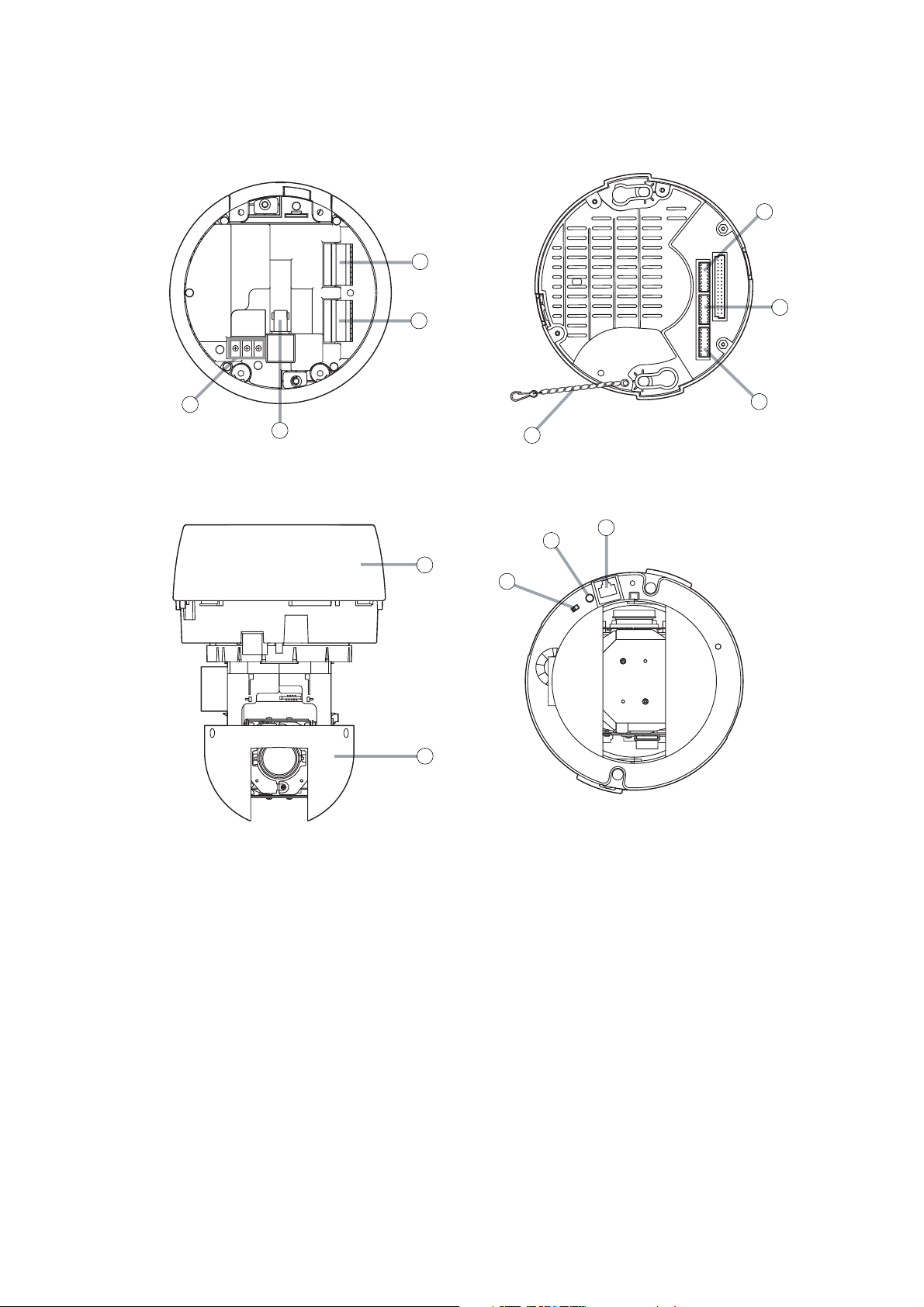
(1) Power supply terminal
(2) Video output terminal (VIDEO OUT)
(3) Connector (CN1)
(4) Connector (CN2) *
1
(5) Safety wire
(6) DIP switch (SW1)
(7) DIP switch (SW2)
(8) DIP switch (SW3)
(9) Base unit
(10) Camera unit
(11) COM SW *
2
(12) COM LED *
2
(13) COM PORT *
2
[ Top view ]
[ Camera Unit Section, Top view ]
[ Front view ]
[ Camera Unit Section, Bottom view ]
*1C-CC564 C-CC574 only
*2For use of (11), (12) and (13), refer to the "Camera Controller Software Operation Manual" on the
enclosed CD-R.
5. NOMENCLATURE
1
2
6
3
7
4
8
5
13
12
9
11
10
Page 8
8
Notes
• Mount the camera to a heavy-duty ceiling surface (such as concrete ceiling).
• When mounting directly to the ceiling (such as a double ceiling) not strong enough to support the weight of
the mounted camera, use the optional C-BC511A Ceiling Mounting Bracket.
• When installing the camera in the ceiling to hide it as much as possible, use the optional C-BC511U or
C-BC511U-S Flush Ceiling Mounting Bracket.
• When hanging the camera from the ceiling, use the optional C-BC511P Ceiling Suspension Bracket.
• When mounting the camera to a wall, use the optional C-BC511W Wall Mounting Bracket.
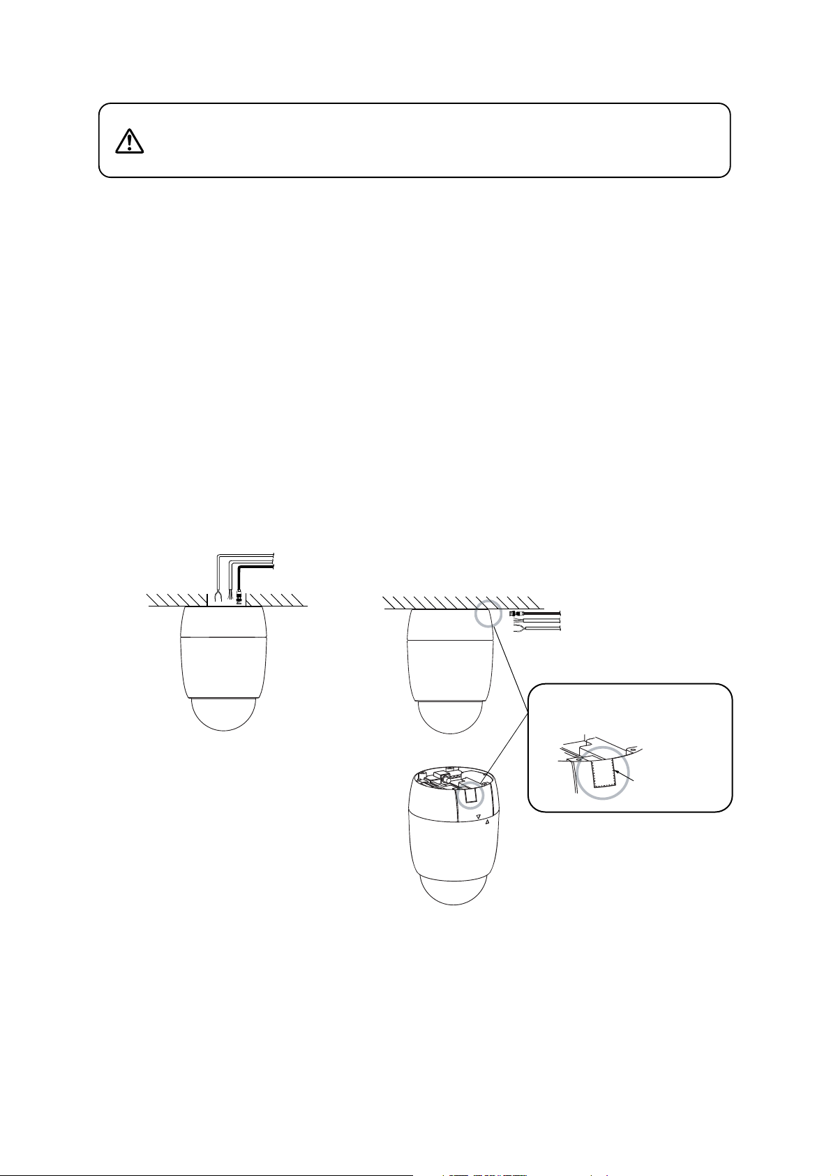
[ Cable routing to the attic ]
[ Cable routing over the ceiling surface ]
Use the C-BC511C or C-BC511C-S Ceiling Mounting Cover.
7.1. Mounting Example
6. PRECAUTIONS WHEN INSTALLING THE UNIT
The combination camera weight 1.7kg. Select the heavy-duty
mounting surface that can structurally support the weight of the
camera. Doing otherwise may result in the unit falling and possibly
causing personal injury.
WARNING
7. DIRECT CEILING MOUNTING
Cut out this portion along
the perforated slot using nippers.
Perforated slot
Page 9
9
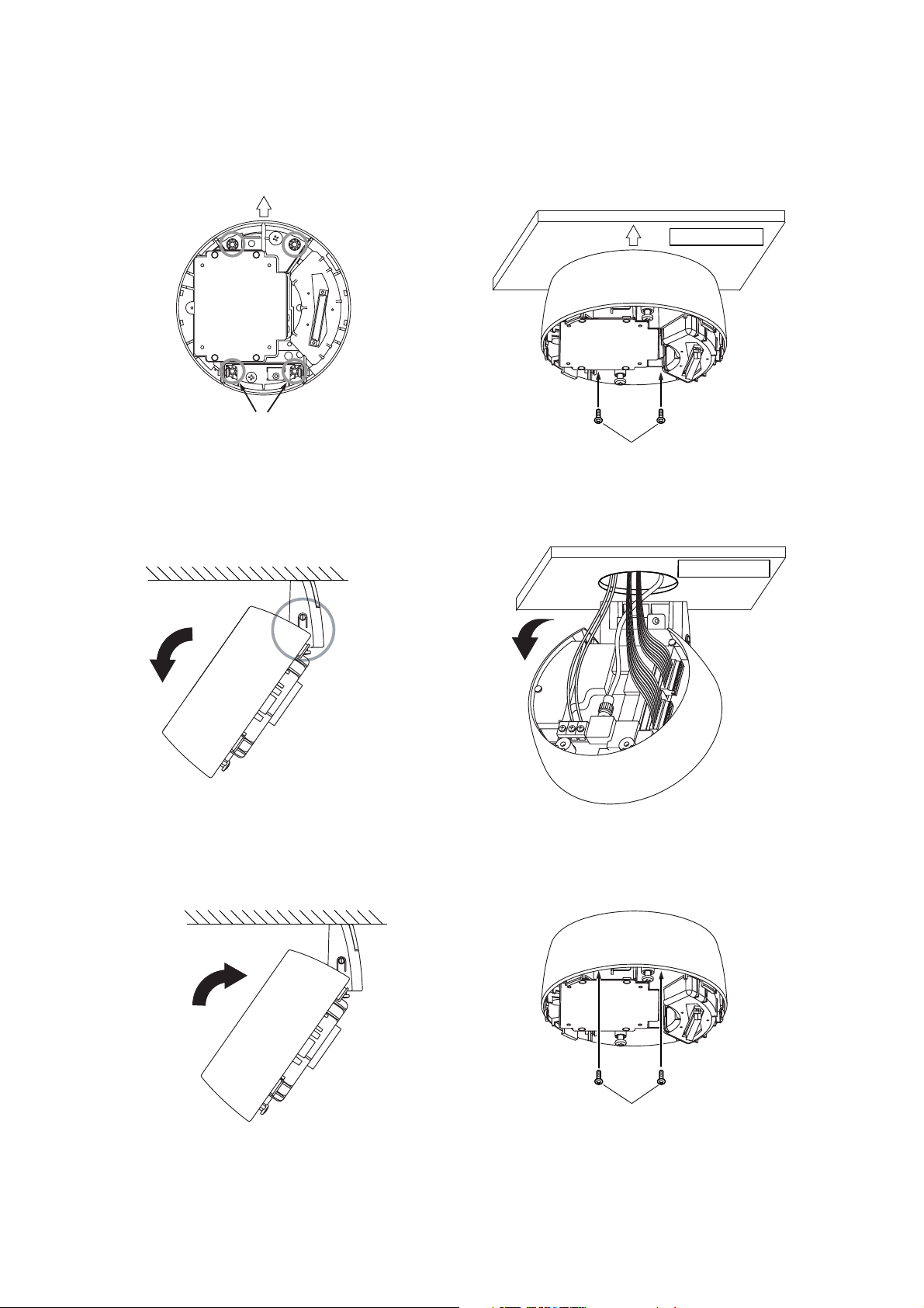
7.2. Mounting Procedures
1. Mount the base unit to the ceiling.
First fix two of the base unit mounting holes as shown below.
Since no mounting screws are supplied with the camera, prepare them separately.
Use screws with a nominal diameter of 4 mm and a length of over 25 mm.
2. Release the lock on the hinged portion of the base unit and connect the power, video, and signal cables to
the base unit.
(For details, please refer to p. 29; "Connections.")
3. Push up and lock the hinged portion of the base unit and secure the remaining two mounting holes.
Camera direction
Secure these two holes first.
(Base unit mounting holes)
Camera direction
Ceiling surface
Mounting screws
Ceiling surface
Open
Hinged portion
Open
Close
Mounting screws
Page 10
10
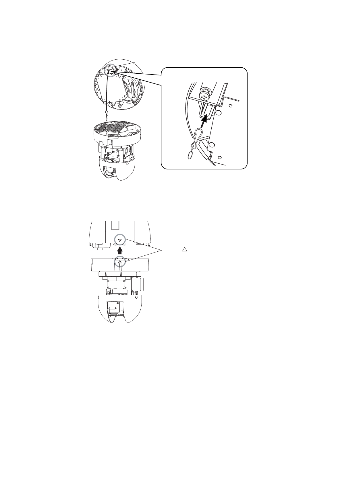
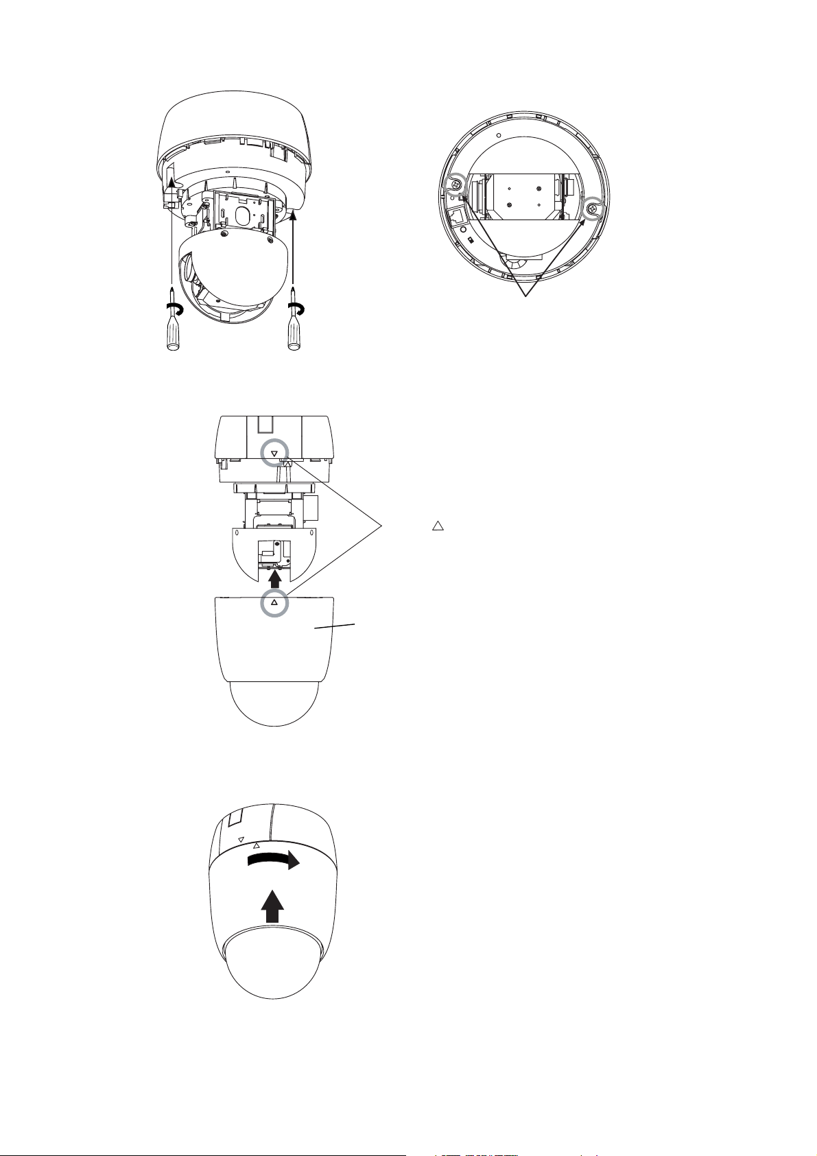
6. Align the positioning mark on the base unit with that on the camera unit.
4. Perform DIP SW settings on the camera unit.
(For details, please refer to p. 31; "DIP Switch Settings.")
5. Attach the safety wire from the camera unit to the wire mounting hole of the base unit.
Wire mounting bracket
Align the marks
Page 11
11
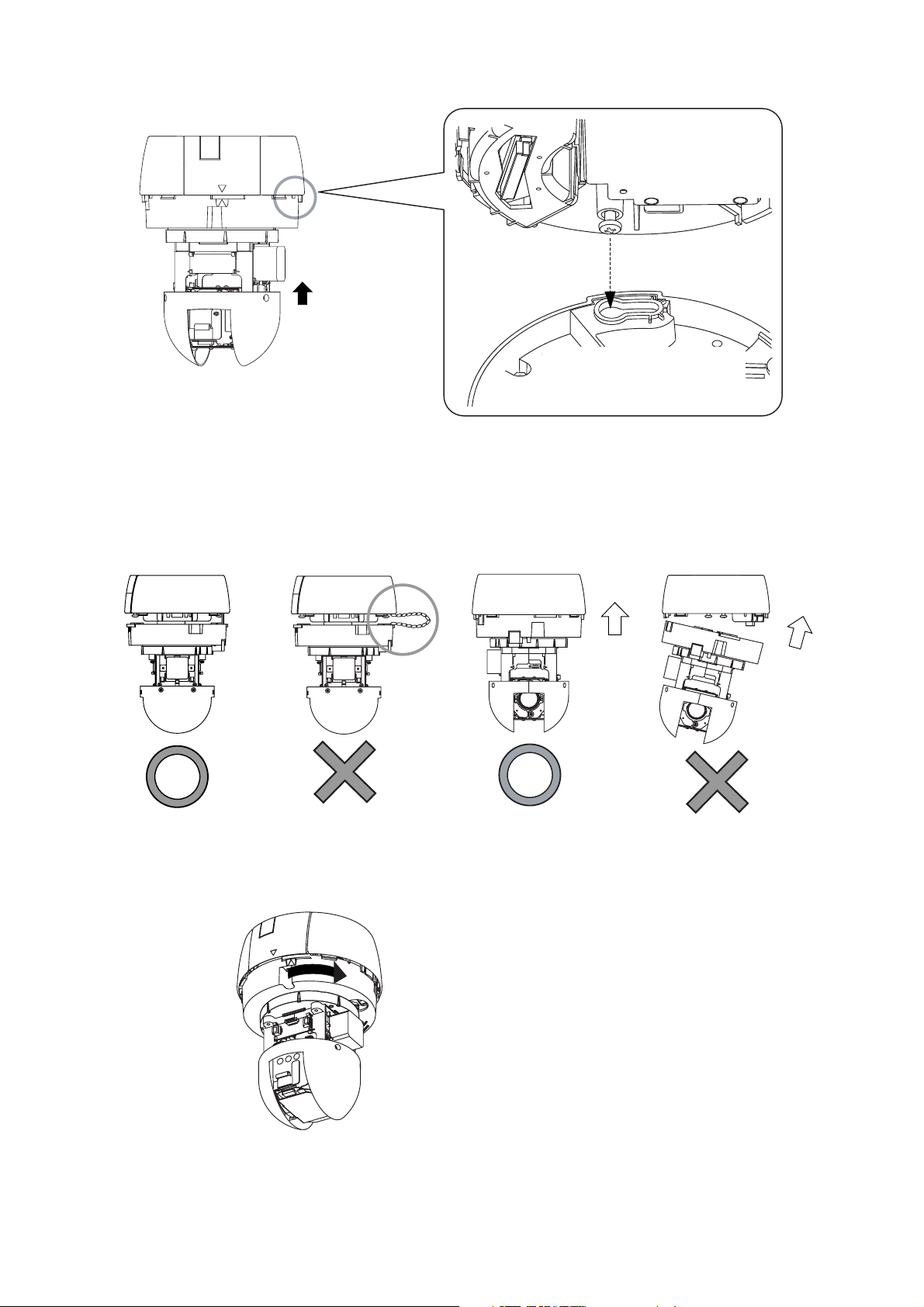
Note
When mounting the camera unit to the base unit,
mount it straight till it is attached to the base unit
correctly. Mounting it at an angle may cause
damage to the camera unit.
8. Turn the camera unit clockwise pushing it up to the base unit until it locks into place.
Note
Take care not to pinch the safety wire between the
camera unit and base unit to avoid damage to the
camera.
7. Align the positioning marks, then push the camera unit up into the base unit.
Push up
Screw section inside the base unit
is to be inserted into the oval hole
in the camera unit.
Mount straight
An
g
led installation
Page 12
12
9. Tighten 2 camera unit mounting screws.
10. Align the positioning mark on the ceiling mounting cover with that on the base unit.
11. Turn the ceiling mounting cover clockwise pushing it up to the base unit until it locks into place.
Tighten
Align the marks
Ceiling mounting cover
C-BC511C
C-BC511C-S
Page 13
13
8. MOUNTING THE CAMERA TO A WEAK CEILING PANEL
Use the optional C-BC511C or C-BC511C-S Ceiling Mounting Cover and the optional C-BC511A Ceiling
Mounting Bracket.
Notes
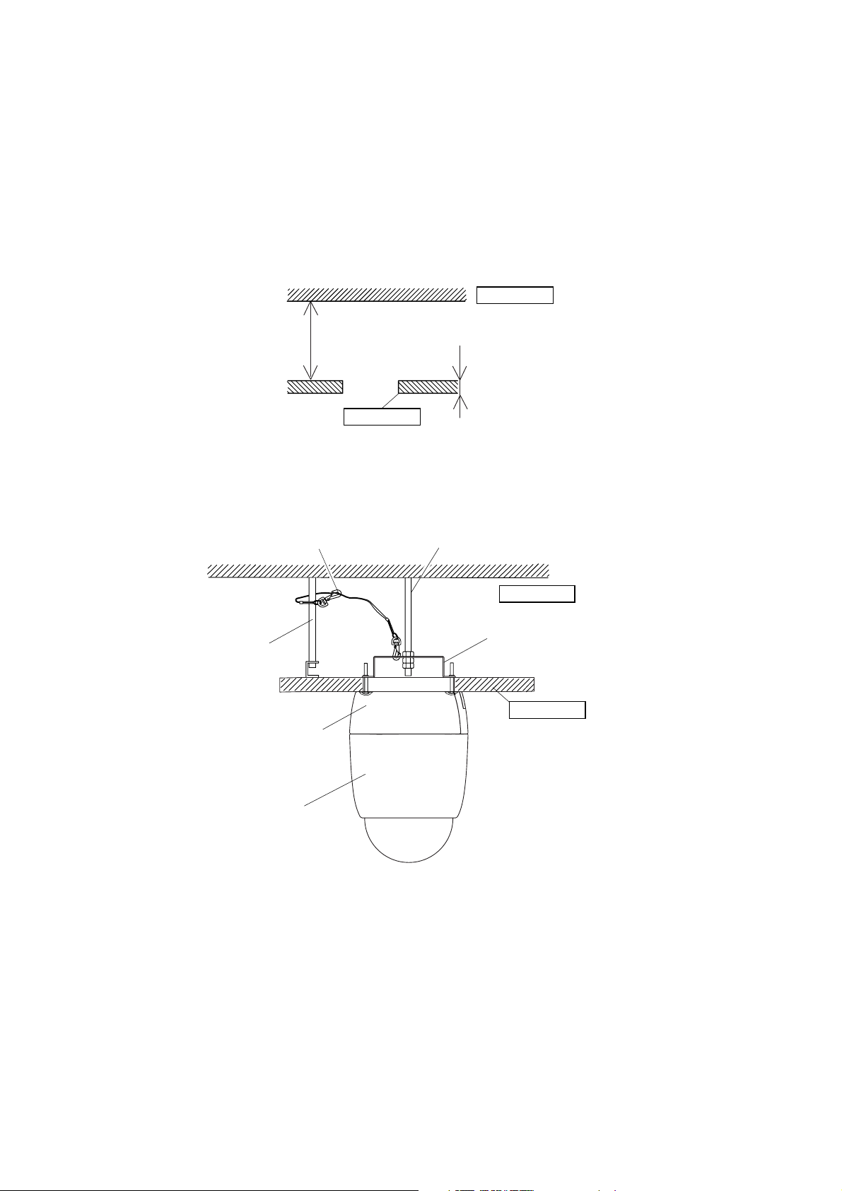
• Use the cover and the anchor whenever the space between suspended ceiling panel and upper ceiling
exceeds a height of 100 mm.
• The ceiling panel to which the camera will be mounted must be no more than 40 mm in thickness.
• Be sure to use the supplied safety wire.
• Be sure to use the specified screws to mount the combination camera and direct mounting anchor, and
ensure that they are securely mounted without any play.
8.1. Mounting Example
Upper ceiling
100 mm or more
40 mm or less
Ceiling panel
Safety wire
(supplied with the C-BC511A)
Anchor bolt for safety wire
Combination camera
C-BC511C, CC-BC511C-S
Ceiling Mounting Cover (optional)
Anchor bolt for ceiling mounting bracket
Upper ceiling
C-BC511A
Ceiling Mounting Bracket (optional)
Ceiling panel
Page 14
14
8.2. Mounting Procedures
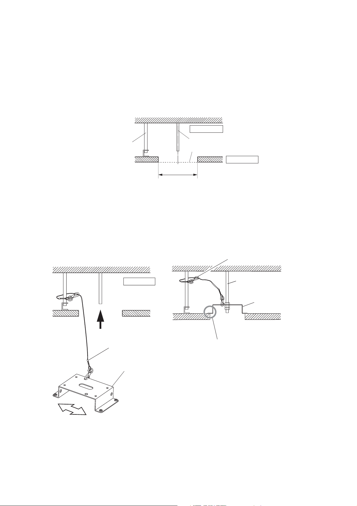
1. Make a mounting hole of ø140 mm in the ceiling panel.
2. Install the anchor bolt for ceiling mounting bracket and anchor bolt for safety wire into the upper ceiling.
Notes
• The anchor bolt for ceiling mounting bracket must be aligned with the center of the mounting hole of ø140
mm in the ceiling panel, and must not project from the ceiling surface.
• If an existing anchor bolt is available nearby, it can be substituted for the anchor bolt for safety wire.
3. Attach the supplied safety wire to the anchor bolt for safety wire.
4. Attach the ceiling mounting bracket to the end of the safety wire.
5. Attach the ceiling mounting bracket to the anchor bolt for ceiling mounting bracket.
Upper ceiling
Anchor bolt for safety wire
ø140 mm
Upper ceiling
3
Anchor bolt for ceiling mounting bracket
Ceiling surface
Ceiling panel
Safety wire
Anchor bolt for ceiling
mounting bracket
C-BC511A
Ceiling Mounting Bracket
(optional)
4
Camera direction
Safety wire
(supplied with the C-BC511A)
C-BC511A
Ceiling Mounting Bracket
(optional)
5
Ensure close contact here.
*
Page 15

15
8. For subsequent procedures, follow the steps 1 – 11 on p. 9 – 12.
6. Attach the supplied safety wire to the base unit.
7. Attach the safety wire connected to the base unit to the ceiling mounting bracket.
Use screws M3 x 8
tightened to the base unit.
Page 16

16
9. FLUSH CEILING MOUNTING
• Use the optional C-BC511U or C-BC511U-S Flush Ceiling Mounting Bracket.
• Flush mounting can be used to reduce the camera's exposed area. Use the optional C-BC511U or CBC511U-S Flush Ceiling Mounting Bracket when mounting cameras to gypsum board ceilings or other weak
ceiling panel materials in which mounting screws cannot be securely inserted.
Notes
• Use the bracket whenever the space between suspended ceiling panel and upper ceiling exceeds a height
of 250 mm.
• The ceiling panel to which the camera will be mounted must be no more than 40 mm in thickness.
• Be sure to use the supplied safety wire.
• Be sure to use the specified screws to mount the combination camera and flush ceiling mounting bracket,
and ensure that they are securely mounted without any play.
9.1. Mounting Example
Upper ceiling
250 mm or more
40 mm or less
Ceiling panel
Safety wire
(supplied with the C-BC511U
and C-BC511U-S)
Anchor bolt for
safety wire
Ceiling panel
Anchor bolt for flush ceiling
mounting bracket
Upper ceiling
C-BC511U or C-BC511U-S
Flush Ceiling Mounting Bracket
(optional)
Combination camera
Page 17

17
9.2. Mounting Procedures
1. Make a mounting hole of ø230 mm in the ceiling panel.
2. Install the anchor bolt for flush ceiling mounting bracket and anchor bolt for safety wire into the upper
ceiling.
• The anchor bolt for flush ceiling mounting bracket must be aligned with the center of mounting hole of
ø230 mm in the ceiling panel.
• Use the pattern paper supplied with the C-BC511U or C-BC511U-S bracket to determine the anchor bolt
length and mounting surface height.
• If an existing anchor bolt is available nearby, it can be substituted for the anchor bolt for safety wire.
3. Attach the base unit to the flush ceiling mounting bracket.
First fix two of the base unit mounting holes as shown below.
(Use the machine screws supplied with the combination camera.)
Anchor bolt for safety wire
Upper ceiling
Ceiling panel
ø230 mm
Camera direction
Anchor bolt for flush ceiling
mounting bracket
Mounting surface
Paper pattern
(supplied with the C-BC511U or C-BC511U-S)
Machine screws M4 x 8
(supplied with the combination camera)
Secure these two holes first.
(Base unit mounting holes)
Camera direction
Camera front
Page 18

18
6. Release the lock on the hinged portion of the base unit and run the video, transmission and power cables
extending from the ceiling through the flush ceiling mounting bracket's cable entry opening.
4. Attach the supplied safety wire to the anchor bolt for safety wire.
5. Attach the flush ceiling mounting bracket to the end of safety wire.
Upper ceiling
4
Anchor bolt flush ceiling
mounting bracket
5
ra
ction
e
Notch
Open
Hinged portion
Came
dir
Cable entry opening
Page 19

19
9. Perform steps 3 – 5 on p. 9 – 10.
7. Place the flush ceiling mounting bracket in the ceiling behind the ceiling panel by inserting it through the
mounting hole in the ceiling panel, then secure the bracket using the three supplied ceiling mounting
screws.
Turning the mounting screws clockwise clamps the ceiling holding plate to the ceiling panel. Ensure that the
notch in the bracket is pointing in the camera's intended direction.
8. Fix the flush ceiling mounting bracket to the anchor bolt for flush ceiling mounting and connect the video,
communications, and power cables to the base unit.
(For details, please refer to p. 29; "Connections.")
Flush ceiling mounting
bracket
Ceiling holding plate
Ceiling panel
7
Turn clockwise.
Tighten
Ceiling panel
mounting screws
Notch
ra direction
Came
Page 20

20
10. Attach the camera unit to the base unit.
Align the positioning mark on the camera unit with that on the flush ceiling mounting bracket.
11. Perform steps 7 – 9 on p. 11 – 12.
12. Align the positioning mark on the supplied dome cover with the notch in flush ceiling mounting bracket.
13. Turn the dome cover counterclockwise pushing it up to the flush ceiling mounting bracket until it locks into
place.
Align the notch with mark.
12
Align the notch
with mark.
13
Page 21

21
10. CEILING SUSPENSION
Use the optional C-BC511P Ceiling Suspension Bracket in combination with the optional C-BC511C or CBC511C-S Ceiling Mounting Cover when suspending the camera from a ceiling.
Notes
• Be sure to mount the ceiling suspension bracket using the supplied safety wire.
• Be sure to use the specified screws to mount the combination camera and ceiling suspension bracket, and
ensure that they are securely mounted without any play.
10.1. Mounting Example
• When suspending the camera from a double-
constructed ceiling
• When suspending the camera from the strong
ceiling materials
Saddle bracket
Footing
Top cover
Anchor bolt for
safety wire
Suspension plate
(separately required part)
C-BC511P Ceiling Suspension
Bracket (optional)
Combination camera
C-BC511C or C-BC511C-S
Ceiling Mounting Cover
(optional)
Upper ceiling
Safety wire
(supplied with the
C-BC511P)
Ceiling plate
Footing/Saddle
Page 22

22
4. Detach footings and saddle bracket on the camera mounting side from the suspension pipe.
• Removed saddle brackets and screws are attached to the suspension pipe in step 10.
• Removed footings and screws are attached to the base unit in step 12.
10.2. Mounting Procedures
1. Determine the suspending position, then make a mounting hole of ø50 – 60 mm in the ceiling plate.
2. Install the anchor bolt for safety wire into the upper ceiling.
• If an existing anchor bolt is available nearby, it can be substituted for the anchor bolt for safety wire.
3. Separately prepare a suspension plate, and cut out the necessary hole in a way best suited to the plate
material.
• For strong ceiling materials
• For double-constructed ceilings
Anchor bolt for
safety wire
2
1
Ceiling panel
ø50 mm – 60 mm
Suspension plate
Camera direction
Paper pattern
Ceiling plate
Saddle bracket and footing
on the camera mounting side
C-shaped channel
Suspension plate
Ceiling panel
Suspension pipe
Page 23

23
5. Attach the suspension pipe (saddle bracket and footing) to the suspension plate.
Note: Ensure that the installed suspension pipe faces in the intended camera orientation.
6. Install the suspension plate behind the ceiling panel.
• When installing in double-constructed ceilings:
Place the suspension plate across two C-channel bars with its hole aligned with the corresponding hole in
the ceiling panel.
• When installing in strong ceiling materials:
Install the suspension plate with its hole aligned with the corresponding hole in the ceiling panel.
7. Attach the supplied safety wire to the anchor bolt for safety wire.
8. Attach the end of the safety wire to the saddle bracket of the suspension pipe.
9. Run the video, power cable and communications cables extending from the ceiling through the pipe.
[Mounting hole dimensional diagram]
81
Footing
Camera
orientation
Saddle bracket
Suspension pipe
40
70
46
Unit: mm
Video/ Power/ Communications cables
9
6
Suspension plate
(to be prepared separately)
Saddle bracket
Ceiling panel
Anchor bolt for safety wire
Safety wire
8
(supplied with the C-BC511P)
C-channel bar
(to be prepared separately)
Suspension pipe
Upper ceiling
7
Page 24

24
11. Attach the supplied safety wire to the base unit.
12. Attach removed footings to the base unit.
• First fix two of the base unit mounting holes as shown below.
• Use the screws supplied with the combination camera.
10. Attach two saddle brackets to the suspension pipe.
• Align the screw installed in the saddle bracket with the hole in the pipe.
• Attach the saddle bracket so that the orientation of its oval holes is as shown in the figure.
Note: Ensure that the saddle brackets are securely fixed without any play.
Saddle bracket
Screw
Oval hole
Suspension pipe
mounted to the ceiling.
Use screws M3 x 8
tightened to the base unit.
Camera direction
Secure these two holes first.
(Base unit mounting holes)
Footing
Camera
direction
M4 x 8 machine screw
(supplied with the combination camera)
Page 25

25
13. Attach the safety wire attached to the base unit to the saddle bracket of the suspension pipe.
14. Attach the base unit (with footing) to the suspension pipe.
• Run the camera mounting screw head (2 screws) through the oval hole in the saddle bracket, and slide it in
the direction indicated by the arrow, then tighten the camera mounting screws.
• Tighten the safety screw and run its screw tip through the round hole in the saddle bracket.
Note: Ensure that camera mounting screws and safety screw are securely tightened.
Oval hole in the saddle bracket
M4 x 20 Camera mounting
screw
M5 x 20 Safety screw
Base unit
Camera
direction
Screw head
sliding direction
Page 26

26
15. Release the lock on the hinged portion of the base unit and connect the power, video, and signal cables to
the base unit.
(For details, please refer to p. 29; "Connections.")
16. Lock the hinged portion of the base unit and secure the remaining two mounting holes.
17. Perform steps 4 – 11 on p. 10 – 12.
18. Mount the top cover by inserting the tabs of one half of the cover into the slots of the other half.
Open
Hinged portion
Open
Close
Hinged portion
M4 x 8 screws supplied
with the combination camera
Top cover
Ta b
Ta b
Top cover
Camera direction
Page 27

27
11. WALL MOUNTING
Use the optional C-BC511W Wall Mounting Bracket and optional C-BC511C or C-BC511C-S, Ceiling
Mounting Cover.
Note
Be sure to use the specified screws to mount the combination camera and wall mounting bracket, and ensure
that they are securely mounted without any play.
11.1. Mounting Example
11.2. Mounting Procedures
1. Determine the mounting position, then make a mounting hole of ø50 – 60 mm on a wall.
2. Detach footings on the camera mounting side from the suspension pipe.
Removed footings and screws are attached to the base unit later. (refer to p. 24)
Top cover
C-BC5111W
Wall Mounting Bracket
(optional)
Top cover
Combination camera
C-BC511C or C-BC511C-S
Ceiling Mounting Cover (optional)
Wall surface
Saddle bracket and footing
Suspension pipe
Footings and saddle bracket
on the camera mounting side
Page 28

28
4. Perform steps 11 – 16 on p. 24 – 26.
5. Attach the top cover. Insert one top cover's clicks into the other top cover's slots.
Mount the top cover by inserting the tabs of one half of the cover into the slots of the other half.
3. Mount the suspension pipe (with saddle bracket and footings) on a wall.
Notes
• Since no mounting screws are supplied with the camera, prepare them separately.
• Use screws with a nominal diameter of 4 mm.
Cable entry hole
on the wall surface
Mounting screw
Wall surface
[Mounting hole dimensional diagram]
81
70
46
Mounting screw
40
Ta b
Top cover
Ta b
Unit: mm
Top cover
Camera direction
Page 29

29
12.1. Precautions When Installing the Camera
• Avoid install the camera cable in close proximity to other cables of electric products, such as fluorescent
lamps. Failure to do this could downgrade the picture quality.
• Installing the camera near the strong electric or magnetic field produced by television transmitting antennas,
motors or transformers could distort or shake the monitor screen. In such cases, install the cables in the
sheet steel cable piping.
• Before applying the power to the camera, be sure to complete all connections between the camera and
related equipment.
Connector 1 (CN1) Connector 2 (CN2)
GND NC (Normally Close)
Alarm 3 COM
Alarm 2 NO (Normally Open)
Alarm 1 Alarm 8
AUX (Open Collector) Alarm 7
GND Alarm 6
B (RS-485) (–) Alarm 5
A (RS-485) (+) Alarm 4
Terminal No.
(1)
(2)
(3)
(4)
(5)
(6)
(7)
(8)
12. CONNECTIONS
Power input
Connect to the power supply.
Connector 1 (CN1)
No. 1 – 5: Alarm Input/Output terminal
Connect to the sensor of no-voltage make contact
or the external equipment to be controlled using
the auxiliary contact output.
No. 6 – 8 Camera control terminal
When controlling the camera using the RS-485
communication line, connect to the cable from
remote controller or other camera.
Connector 2 (CN2) (C-CC564 C-CC574 only)
No. 1 – 8: Alarm input/Output terminal
Connect to the sensor of no-voltage make contact
or the external equipment to be controlled using
the auxiliary contact output.
Video output
When controlling the camera using the RS-485
communication line, connect to the video input terminal
of multi-switcher or monitor.
Page 30

30
Rated, Maximum permissible voltage: 20 V DC
Permissible current limit: 1 A
Contact useful life: 100,000 times
13.3. About Alarm Input
No-voltage make contact input
Rated: open voltage: 18 V DC, short-circuit current: under 2 mA
13. CAMERA SETTINGS
13.1. About AUX Output 1
Open collector output
Rated: withstand voltage: 20 V DC, permissible current: under 100 mA
13.2. About AUX Output 2 (C-CC564, C-CC574 only)
12.2. Camera Control Connector Connection (RS-485)
• Connect terminals (+) and (–) of the C-RM500 Remote Controller or the C-IF500 Interface Unit to the
camera's terminals (+) (terminal No. 8) and (–) (terminal No. 7), respectively.
• Connect the camera's terminals (+) and (–) to the next camera's terminals (+) and (–) in order.
Notes
• The maximum number of units connectable to a pair of RS-485 lines (from termination to termination) is 32
units including the Remote Controller. The maximum cable length connecting each terminal is 1.2 km in
total.
• The camera may not operate correctly if 32 or more units are connected or the total cable distance exceeds
1.2 km. In such cases, split or extend wiring using the C-IF500 Interface Unit.
• Indoor-use and outdoor-use combination cameras can be wired in free combinations.
Shield twisted pair cable
Connect to the next
camera's terminal
Connect to remote controller's
camera control terminal
GND
Camera control
cable
GND
Camera control
cable
Normal Alarm
NO – COM
NC – COM
Open
Short
Short
Open
[ Normal ]
NO
[ Alarm ]
NO
COM
NC
COM
NC
Page 31

31
13.4. DIP Switch Settings
Notes
• Set the unused DIP switches to the "OFF" position.
• If the DIP switches are not set correctly, the camera does not operate correctly.
DIP SW1 DIP SW2 DIP SW3
No.1
Camera address setting switch 1
No.2
Camera address setting switch 2
DIP SW1
DIP SW3
Communication speed setting
switch 1
Communication speed setting
switch 2
DIP SW2
Firmware update switch 1
Firmware update switch 2
No.3
Camera address setting switch 3
No.4
Camera address setting switch 4
No.5
Camera address setting switch 5
No.6
Camera address setting switch 6
Camera address setting switch 7
No.7
No.8
Camera address setting switch 8
OSD switch
Unused
Unused
Communication method selector
switch
Unused
Termination switch
Firmware update switch 3
Unused
Unused
Unused
Memory clear switch
Unused
Page 32

32
13.4.1. Camera Address Setting Switch (DIP Switch 1: No. 1 – 8)
Used to set camera address when using the camera in connection with the C-RM500 Remote Controller. Set
the DIP switch so that the address is equal to the connected switcher's channel number. The relationship
between switch settings and camera addresses are shown in the attached table (p. 33).
(Factory setting: Only No.1 is "ON".)
Note
If the address switch number does not match with the connected switcher's channel number or if set to the
same number as that of other camera connected to the same system, the system does not operate correctly.
13.4.5. Termination Switch (DIP switch 2: No. 8)
Set the switch of the camera last connected to the RS-485 communications line to ON. (Factory setting: OFF)
13.4.2. Communication Speed Setting Switch (DIP switch 2: No. 1 – 2)
Check to be sure that the communication speed set here is the same as that of the Remote Controller. When
changing the speed, change settings of all cameras and Remote Controller within the system.
(Factory setting: 38,400 bps.)
13.4.3. OSD Switch (DIP switch 2: No. 3)
When this switch is set to the OFF position, the initial screen does not disappear until communications with
other equipment are established following initial operation after the power has been switched ON.
(Factory setting: OFF)
13.4.4. Communication Method Selector Switch (DIP switch 2: No. 6)
Chooses the RS-485 communication method from Type A (used with the C-RM500 Remote Controller) and
Type B. Set the switch to the OFF position to choose Type A, and to the ON position to choose Type B.
(Factory setting: ON)
13.4.6. Firmware Update Switch (DIP switch 3: No. 1 – 3)
No.1: Used to update Master CPU firmware.
No.2: used to update Slave CPU firmware.
No.3: Temporarily pauses the initial operation.
For details, please refer to the "Camera Controller Software Operation Manual" on the enclosed CD-R.
13.4.7. Memory Clear Switch (DIP switch 3: No. 7)
Switching on the power with this switch set to the ON position returns all camera settings to the initial setting.
The indication "Memory Clear" is displayed on the screen while clearing memory. After the indication has
disappeared, turn off the power and set the switch to the OFF position.
Note: Clock information and backup data are not erased.
No.1
No.2
bps
OFF OFF 38,400
O N OFF 19,200
OFF O N 9,600
O N O N 4,800
Page 33

33
[ Camera address setting switch 1 – 64 ]
No. No. No. No.
DIP switch 1 DIP switch 1 DIP switch 1 DIP switch 1
ON
ON
ON
ON
1173349
12345678
12345678
12345678
12345678
ON
ON
ON
ON
2183450
12345678
ON
12345678
ON
12345678
ON
12345678
ON
3193551
12345678
ON
12345678
ON
12345678
ON
12345678
ON
4203652
12345678
ON
12345678
ON
12345678
ON
12345678
ON
5213753
12345678
ON
12345678
ON
12345678
ON
12345678
ON
6223854
12345678
ON
12345678
ON
12345678
ON
12345678
ON
7233955
12345678
ON
12345678
ON
12345678
ON
12345678
ON
8244056
12345678
12345678
12345678
12345678
ON
ON
ON
ON
9254157
12345678
ON
12345678
ON
12345678
ON
12345678
ON
10 26 42 58
12345678
ON
12345678
ON
12345678
ON
12345678
ON
11 27 43 59
12345678
ON
12345678
ON
12345678
ON
12345678
ON
12 28 44 60
12345678
ON
12345678
ON
12345678
ON
12345678
ON
13 29 45 61
12345678
ON
12345678
ON
12345678
ON
12345678
ON
14 30 46 62
12345678
ON
12345678
ON
12345678
ON
12345678
ON
15 31 47 63
12345678
12345678
12345678
12345678
ON
ON
ON
16 32 48 64
12345678
12345678
12345678
ON
12345678
Page 34

34
[ Camera address setting switch 65 – 128 ]
No.
DIP switch 1
ON
No.
DIP switch 1
ON
No.
DIP switch 1
ON
65 81 97 113
12345678
12345678
12345678
No.
DIP switch 1
ON
12345678
ON
ON
ON
66 82 98 114
12345678
ON
12345678
ON
12345678
ON
67 83 99 115
12345678
ON
12345678
ON
12345678
ON
68 84 100 116
12345678
ON
12345678
ON
12345678
ON
69 85 101 117
12345678
ON
12345678
ON
12345678
ON
70 86 102 118
12345678
ON
12345678
ON
12345678
ON
71 87 103 119
12345678
ON
12345678
ON
12345678
ON
72 88 104 120
12345678
12345678
12345678
ON
12345678
ON
12345678
ON
12345678
ON
12345678
ON
12345678
ON
12345678
ON
12345678
ON
ON
ON
73 89 105 121
12345678
ON
12345678
ON
12345678
ON
74 90 106 122
12345678
ON
12345678
ON
12345678
ON
75 91 107 123
12345678
ON
12345678
ON
12345678
ON
76 92 108 124
12345678
ON
12345678
ON
12345678
ON
77 93 109 125
12345678
ON
12345678
ON
12345678
ON
78 94 110 126
12345678
ON
12345678
ON
12345678
ON
79 95 111 127
12345678
12345678
12345678
ON
12345678
ON
12345678
ON
12345678
ON
12345678
ON
12345678
ON
12345678
ON
12345678
ON
ON
ON
80 96 112 128
12345678
12345678
12345678
ON
12345678
Page 35

35
[ Camera address setting switch 129 – 192 ]
No.
DIP switch 1
ON
No.
DIP switch 1
ON
No.
DIP switch 1
ON
129 145 161 177
12345678
12345678
12345678
No.
DIP switch 1
ON
12345678
ON
ON
ON
130 146 162 178
12345678
ON
12345678
ON
12345678
ON
131 147 163 179
12345678
ON
12345678
ON
12345678
ON
132 148 164 180
12345678
ON
12345678
ON
12345678
ON
133 149 165 181
12345678
ON
12345678
ON
12345678
ON
134 150 166 182
12345678
ON
12345678
ON
12345678
ON
135 151 167 183
12345678
ON
12345678
ON
12345678
ON
136 152 168 184
12345678
12345678
12345678
ON
12345678
ON
12345678
ON
12345678
ON
12345678
ON
12345678
ON
12345678
ON
12345678
ON
ON
ON
137 153 169 185
12345678
ON
12345678
ON
12345678
ON
138 154 170 186
12345678
ON
12345678
ON
12345678
ON
139 155 171 187
12345678
ON
12345678
ON
12345678
ON
140 156 172 188
12345678
ON
12345678
ON
12345678
ON
141 157 173 189
12345678
ON
12345678
ON
12345678
ON
142 158 174 190
12345678
ON
12345678
ON
12345678
ON
143 159 175 191
12345678
12345678
12345678
ON
12345678
ON
12345678
ON
12345678
ON
12345678
ON
12345678
ON
12345678
ON
12345678
ON
ON
ON
144 160 176 192
12345678
12345678
12345678
ON
12345678
Page 36

36
[ Camera address setting switch 193 – 255 ]
No.
DIP switch 1
ON
No.
DIP switch 1
ON
No.
DIP switch 1
ON
193 209 225 241
12345678
12345678
12345678
No.
DIP switch 1
ON
12345678
ON
ON
ON
194 210 226 242
12345678
ON
12345678
ON
12345678
ON
195 211 227 243
12345678
ON
12345678
ON
12345678
ON
196 212 228 244
12345678
ON
12345678
ON
12345678
ON
197 213 229 245
12345678
ON
12345678
ON
12345678
ON
198 214 230 246
12345678
ON
12345678
ON
12345678
ON
199 215 231 247
12345678
ON
12345678
ON
12345678
ON
200 216 232 248
12345678
12345678
12345678
ON
12345678
ON
12345678
ON
12345678
ON
12345678
ON
12345678
ON
12345678
ON
12345678
ON
ON
ON
201 217 233 249
12345678
ON
12345678
ON
12345678
ON
202 218 234 250
12345678
ON
12345678
ON
12345678
ON
203 219 235 251
12345678
ON
12345678
ON
12345678
ON
204 220 236 252
12345678
ON
12345678
ON
12345678
ON
205 221 237 253
12345678
ON
12345678
ON
12345678
ON
206 222 238 254
12345678
ON
12345678
ON
12345678
ON
207 223 239 255
12345678
12345678
12345678
ON
12345678
ON
12345678
ON
12345678
ON
12345678
ON
12345678
ON
12345678
ON
12345678
ON
ON
208 224 240
12345678
12345678
ON
12345678
Page 37

37
14. SYSTEM EXAMPLES
Combination camera
Outdoor combination camera
Multi-switcher
Dedicated remote controller
Monitor
Page 38

38
C-CC514 NT C-CC514 PL
24 V AC, 50/ 60 Hz
9 W (normal operation), 19 W max. (1.3 A max.)
RS-485 communications system (applicable protocol: Type A, Type B)
VBS 1.0 V(p-p), 75 Ω, BNC-R jack
RS-485 camera control connector
3 channels, no-voltage make contact input, open voltage: 18 V DC,
short-circuit current: under 2 mA (settable alarm action)
1 channel, open collector output, withstand voltage: 20 V DC,
permissible current: under 100 mA
Internal synchronization/ power synchronization (phase adjustable when in
power synchronization mode)
8 characters (alphanumeric and symbols)
Camera, Position, Trace, Auto-pan, Tour, Home, Sector, AUX
255 + Home
Auto-pan, Preset sequence, Auto-trace (2 preset patterns (60 s)),
Tour (16 preset patterns)
Refresh: Start at the preset time every day or every week by timer settings
Program: Settable 16 actions
Menu: English, German, French, Italian
ID: English, German, French, Italian, Russian, Polish, Spanish, Portuguese
1/4 type CCD
Horizontal: 480 lines (at center)
50 dB
High-sensitivity function High-sensitivity function
OFF: 1 lx (50 IRE), 0.3 lx (20 IRE) OFF: 1 lx (350 mV), 0.3 lx (140 mV)
ON: 0.03 lx (50 IRE), 0.01 lx (20 IRE) ON: 0.03 lx (350 mV), 0.01 lx (140 mV)
pattern 1/ pattern 2/ pattern 3/ OFF
Slow shutter mode (32 times max.)
ATW/ AWB
Automatic
Automatic correction
12x zooming
One push/ stop AF/ continuous
22x
f = 4.0 – 88 mm (22x)
Horizontal: 47.3° (W) – 2.2° (T), Vertical: 36.5° (W) – 1.7° (T)
F 1.6 (W) – 3.8 (T)
WIDE end to TELE end
Approx. 1.3 s (preset operation), Approx. 2.4 s (manual operation)
Panning: endless 360° rotation, Tilting: +5° to –90°
Panning/ Tilting: 360°/s max. (preset operation), 360°/s max. (manual operation)
Manual limit
–10°C to +50°C (14°F to 122°F)
(continuously active for operation at temperature below 0°C (32°F))
Under 90% RH
(no condensation)
Indoor used
Base: PC/ ABS resin, cool gray
Camera: PC/ ABS resin, black
ø168 x 234 (H) mm (ø6.6 x 9.2 (H) inch)
1.7 kg (3.7 lb)
Model
Power Source
Power Consumption
Control
Video Output
Camera Control Terminal
Alarm Input
Auxiliary Contact Output
Synchronization
ID
No. of Preset Positions
Automatic Operation
Timer
Language
Camera
Image Device
Resolution
S/N Ratio
Minimum Illumination
Backlight Compensation
High-Sensitivity Function
White Balance
Iris
Flicker Reduction
Electronic Zooming
Auto-Focus
Lens
Zooming
Effective Focal Length
Effective Angle of View
Maximum Aperture
Zooming Speed
Pan/Tilt Head
Rotating Range
Rotating Speed
Other Functions
Operating Temperature
Operating Humidity
Application
Finish
Dimensions
Weight
15. SPECIFICATIONS
Note: The design and specifications are subject to change without notice for improvement.
Page 39

39
C-CC564 NT C-CC564 PL
24 V AC, 50/ 60 Hz
9 W (normal operation), 19 W max. (1.3 A max.)
RS-485 communications system (applicable protocol: Type A, Type B)
VBS 1.0 V(p-p), 75 Ω, BNC-R jack
RS-485 camera control connector
8 channels, no-voltage make contact input, open voltage: 18 V DC,
short-circuit current: under 2 mA (settable alarm action)
2 channel, open collector output, withstand voltage: 20 V DC,
permissible current: under 100 mA,
relay contact output, permissible voltage: 20 V DC,
permissible current: under 1 A
Internal synchronization/ power synchronization (phase adjustable when in
power synchronization mode)
8 characters (alphanumeric and symbols)
Camera, Position, Trace, Auto-pan, Tour, Home, Sector, AUX
255 + Home
Auto-pan, Preset sequence, Auto-trace (2 preset patterns (60 s)),
Tour (16 preset patterns)
Refresh: Start at the preset time every day or every week by timer settings
Program: Settable 16 actions
Menu: English, German, French, Italian
ID: English, German, French, Italian, Russian, Polish, Spanish, Portuguese
1/4 type CCD
Horizontal: 480 lines (at center)
50 dB
High-sensitivity function High-sensitivity function
OFF: 3 lx (50 IRE), 1 lx (20 IRE) OFF: 3 lx (350 mV), 1 lx (140 mV)
ON: 0.03 lx (50 IRE), 0.01 lx (20 IRE) ON: 0.03 lx (350 mV), 0.01 lx (140 mV)
WIDE DYNAMIC/ pattern 1/ pattern 2/ pattern 3/ OFF
46 dB (backlight compensation: WIDE DYNAMIC operation)
B/ W mode and slow shutter mode (32 times max.)
ATW/ AWB
Automatic
Automatic correction
12x zooming
One push/ stop AF/ continuous
23x
f = 3.6 – 82.8 mm (23x)
Horizontal: 54° (W) – 2.5° (T), Vertical: 41.6° (W) – 1.9° (T)
F 1.6 (W) – 3.7 (T)
WIDE end to TELE end
Approx. 1.5 s (preset operation), Approx. 2.9 s (manual operation)
Panning: Endless 360° rotation, Tilting: +5° to –185°
Panning/ Tilting: 360°/s max. (preset operation), 360°/s max. (manual operation)
Auto-pan, Freeze Preset, Manual limit, Privacy masking (up to 8),
Motion Detect (each 8 presets at each 4 position)
–10°C to +50°C (14°F to 122°F)
(continuously active for operation at temperature below 0°C (32°F))
Under 90% RH (no condensation)
Indoor used
Base: PC/ ABS resin, cool gray
Camera: PC/ ABS resin, black
ø168 x 234 (H) mm (ø6.6 x 9.2 (H) inch)
1.7 kg (3.7 lb)
Model
Power Source
Power Consumption
Control
Video Output
Camera Control Terminal
Alarm Input
Auxiliary Contact Output
Synchronization
ID
No. of Preset Positions
Automatic Operation
Timer
Language
Camera
Image Device
Resolution
S/N Ratio
Minimum Illumination
Backlight Compensation
Dynamic Range
High-Sensitivity Function
White Balance
Iris
Flicker Reduction
Electronic Zooming
Auto-Focus
Lens
Zooming
Effective Focal Length
Effective Angle of View
Maximum Aperture
Zooming Speed
Pan/Tilt Head
Rotating Range
Rotating Speed
Other Functions
Operating Temperature
Operating Humidity
Application
Finish
Dimensions
Weight
Note: The design and specifications are subject to change without notice for improvement.
Page 40

40
C-CC574 NT
24 V AC, 50/ 60 Hz
9 W (normal operation), 19 W max. (1.3 A max)
RS-485 communications system (applicable protocol: Type A, Type B)
VBS 1.0 V(p-p), 75 Ω, BNC-R jack
RS-485 camera control connector
8 channels, no-voltage make contact input, open voltage: 18 V DC,
short-circuit current: under 2 mA (settable alarm action)
2 channel, open collector output, withstand voltage: 20 V DC,
permissible current: under 100 mA,
relay contact output, permissible voltage: 20 V DC,
permissible current: under 1 A
Internal synchronization/ power synchronization (phase adjustable when in
power synchronization mode)
8 characters (alphanumeric and symbols)
Camera, Position, Trace, Auto-pan, Tour, Home, Sector, AUX
255 + Home
Auto-pan, Preset sequence, Auto-trace (2 preset patterns (60 s)),
Tour (16 preset patterns)
Refresh: Starts at the preset time every day or every week by timer settings
Program: Settable 16 actions
Menu: English, German, French, Italian
ID: English, German, French, Italian, Russian, Polish, Spanish, Portuguese
1/4 type CCD
Horizontal: 540 lines typ. (at center),520 lines min.
50 dB
OFF: 1 lx (50 IRE), 0.3 lx (20 IRE), ON: 0.005 lx (50 IRE), 0.0015 lx (20 IRE)
(Sensitivity ON)
OFF: 0.5 lx (50 IRE), 0.15 lx (20 IRE), ON: 0.0025 lx (50 IRE), 0.00075 lx (20 IRE)
WIDE DYNAMIC/WIDE DYNAMIC 2/ pattern 1/ pattern 2/ pattern 3/ OFF
52 dB (backlight compensation: WIDE DYNAMIC operation)
B/W mode and slow shutter mode (32 times max.)
ATW/ AWB
Automatic
Automatic correction
12 x zooming
One push/ stop AF/ continuous
35 x
f = 3.4 – 119mm (35x)
Horizontal: 55.8° (W) – 1.7° (T), Vertical: 43.3° (W) – 1.3° (T)
F 1.4 (W) – 4.2 (T)
WIDE end to TELE end
Approx. 2 s (preset operation), Approx. 3.2 s (manual operation)
Panning: Endless 360° rotation, Tilting: +5° to –185°
Panning/ Tilting: 360°/s max. (preset operation), 360°/s max. (manual operation)
Auto-pan, Freeze preset, Manual limit, Privacy masking (up to 8),
Motion detect (each 8 presets at each 4 positions),EIS
–10°C to +50°C (14°F to 122°F)
(continuously active for operation at temperature below 0°C (32°F))
Under 90% (no condensation)
Indoor used
Base: PC/ ABS resin, cool gray
Camera: PC/ ABS resin, black
ø168 x 234 (H) mm (ø6.6 x 9.2 (H) inch)
1.7 kg (3.7 lb)
Model
Power Source
Power Consumption
Control
Video Output
Camera Control Terminal
Alarm Input
Auxiliary Contact Output
Synchronization
ID
No. of Preset Positions
Automatic operation
Timer
Language
Camera
Image Device
Resolution
S/N Ratio
Minimum Illumination
(High-sensitivity
function)
Backlight Compensation
Dynamic Range
High-Sensitivity Function
White Balance
Iris
Flicker Reduction
Electronic Zooming
Auto-Focus
Lens
Zooming
Effective Focal Length
Effective Angle of View
Maximum Aperture
Zooming Speed
Pan/Tilt Head
Rotating Range
Rotating Speed
Other Functions
Operating Temperature
Operating Humidity
Application
Finish
Dimensions
Weight
Note: The design and specifications are subject to change without notice for improvement.
Page 41

41
C-CC574 PL
24 V AC, 50/ 60 Hz
9 W (normal operation), 19 W max. (1.3 A max)
RS-485 communications system (applicable protocol: Type A, Type B)
VBS 1.0 V(p-p), 75 Ω, BNC-R jack
RS-485 camera control connector
8 channels, no-voltage make contact input, open voltage: 18 V DC,
short-circuit current: under 2 mA (settable alarm action)
2 channel, open collector output, withstand voltage: 20 V DC,
permissible current: under 100 mA,
relay contact output, permissible voltage: 20 V DC,
permissible current: under 1 A
Internal synchronization/ power synchronization (phase adjustable when in
power synchronization mode)
8 characters (alphanumeric and symbols)
Camera, Position, Trace, Auto-pan, Tour, Home, Sector, AUX
255 + Home
Auto-pan, Preset sequence, Auto-trace (2 preset patterns (60 s)),
Tour (16 preset patterns)
Refresh: Starts at the preset time every day or every week by timer settings
Program: Settable 16 actions
Menu: English, German, French, Italian
ID: English, German, French, Italian, Russian, Polish, Spanish, Portuguese
1/4 type CCD
Horizontal: 540 lines typ. (at center),520 lines min.
50 dB
OFF: 1 lx (350 mV), 0.3 lx (140 mV), ON: 0.005 lx (350 mV), 0.0015 lx (140 mV)
(Sensitivity ON)
OFF: 0.5 lx (350 mV), 0.15 lx (140 mV), ON: 0.0025 lx (350 mV), 0.00075 lx (140 mV)
WIDE DYNAMIC/WIDE DYNAMIC 2/ pattern 1/ pattern 2/ pattern 3/ OFF
52 dB (backlight compensation: WIDE DYNAMIC operation)
B/W mode and slow shutter mode (32 times max.)
ATW/ AWB
Automatic
Automatic correction
12 x zooming
One push/ stop AF/ continuous
35 x
f = 3.4 – 119mm (35x)
Horizontal: 55.8° (W) – 1.7° (T), Vertical: 43.3° (W) – 1.3° (T)
F 1.4 (W) – 4.2 (T)
WIDE end to TELE end
Approx. 2 s (preset operation), Approx. 3.2 s (manual operation)
Panning: Endless 360° rotation, Tilting: +5° to –185°
Panning/ Tilting: 360°/s max. (preset operation), 360°/s max. (manual operation)
Auto-pan, Freeze preset, Manual limit, Privacy masking (up to 8),
Motion detect (each 8 presets at each 4 positions),EIS
–10°C to +50°C (14°F to 122°F)
(continuously active for operation at temperature below 0°C (32°F))
Under 90% (no condensation)
Indoor used
Base: PC/ ABS resin, cool gray
Camera: PC/ ABS resin, black
ø168 x 234 (H) mm (ø6.6 x 9.2 (H) inch)
1.7 kg (3.7 lb)
Model
Power Source
Power Consumption
Control
Video Output
Camera Control Terminal
Alarm Input
Auxiliary Contact Output
Synchronization
ID
No. of Preset Positions
Automatic operation
Timer
Language
Camera
Image Device
Resolution
S/N Ratio
Minimum Illumination
(High-sensitivity
function)
Backlight Compensation
Dynamic Range
High-Sensitivity Function
White Balance
Iris
Flicker Reduction
Electronic Zooming
Auto-Focus
Lens
Zooming
Effective Focal Length
Effective Angle of View
Maximum Aperture
Zooming Speed
Pan/Tilt Head
Rotating Range
Rotating Speed
Other Functions
Operating Temperature
Operating Humidity
Application
Finish
Dimensions
Weight
Note: The design and specifications are subject to change without notice for improvement.
Page 42

42
• Accessories
Safety wire .......................................................................................... 1
Camera mounting screw (machine screw M4 x 8) .............................. 4
CD-R (CAMERA CONTROLLER Software, installation manual) ...... 1
• Optional Products
Ceiling Mounting Cover: C-BC511C/ C-BC511C-S
Flush Ceiling Mounting Bracket: C-BC511U/ C-BC511U-S
Ceiling Suspension Bracket: C-BC511P
Wall Mounting Bracket: C-BC511W
Ceiling Mounting Bracket: C-BC511A
Page 43

43
Page 44

133-05-405-9B
URL: http://www.toa.jp/
 Loading...