

Page 1
WALL MOUNTING BRACKET C-BC704W
INSTRUCTION MANUAL
Thank you for purchasing TOA’s Wall Mounting Bracket. Please carefully follow the instructions in this
manual to ensure long, trouble-free use of your equipment.
1. SAFETY PRECAUTIONS .......................... 2
2. GENERAL DESCRIPTION ........................ 4
3. HANDLING PRECAUTIONS ..................... 4
4. INSTALLATION
4.1. In-wall Wring ........................................ 5
4.2. Open Wring .......................................... 9
5. SPECIFICATIONS ................................... 12
Accessories .............................................. 12
TABLE OF CONTENTS
Page 2
2
When Installing the Unit
• Install the unit only in a location that can structurally support the weight of the unit and the mounting bracket.
Doing otherwise may result in the unit falling down and causing personal injury and/or property damage.
• Do not install the unit in the following locations to avoid a traffic accident or personal injury:
· Locations which block the driving of a car.
· Locations where the unit can strike your body or catch your cloth when getting on or down the car.
• Avoid installing or mounting the unit in unstable locations, such as on a rickety table or a slanted surface.
Doing so may result in the unit falling down and causing personal injury and/or property damage.
• Only use the unit's dedicated mounting hardware. The use of mounting hardware not designated could result
in the unit falling and possibly causing personal injury.
• Do not use other methods than specified to mount the bracket. Extreme force is applied to the unit and the
unit could fall off, possibly resulting in personal injuries.
• Attach the safety wire to the unit. If not attached, the unit could fall off, resulting in personal injury.
• Use nuts and bolts that are appropriate for the ceiling's or wall's structure and composition. Failure to do so
may cause the unit to fall, resulting in material damage and possible personal injury.
• Tighten each nut and bolt securely. Ensure that the bracket has no loose joints after installation to prevent
accidents that could result in personal injury.
• Avoid installing the unit in locations exposed to sea breeze or corrosive gas. The unit or its mounts may be
subject to corrosion, that might cause it to fall or result in other accidents.
• Do not mount the unit in locations exposed to constant vibration. The mounting screws and/or bolts may be
loosened by excessive vibration, potentially causing the unit to fall, which could result in personal injury.
• To prevent lightning strikes, install the unit at least five meters away from a lightning rod, and yet within the
protective range (angle of 45°) of the lightning conductor. Lightning strikes may cause a fire, electric shock
or personal injury.
• When installing the unit in the snowy area, take appropriate measures to prevent snow from lying on the
unit. If the snow lies on the unit, the unit may fall, causing personal injuries.
• Owing to the unit's size and weight, be sure that at least two persons are available to install the unit. Failure
to do so could result in personal injury.
1. SAFETY PRECAUTIONS
• Before installation or use, be sure to carefully read all the instructions in this section for correct and safe
operation.
• Make sure to observe the instructions in this manual as the conventions of safety symbols and messages
regarded as very important precautions are included.
• We also recommend you keep this instruction manual handy for future reference.
Safety Symbol and Message Conventions
Safety symbols and messages described below are used in this manual to prevent bodily injury and property
damage which could result from mishandling. Before operating your product, read this manual first and
understand the safety symbols and messages so you are thoroughly aware of the potential safety hazards.
Indicates a potentially hazardous situation which, if mishandled, could
result in death or serious personal injury.
WARNING
Page 3
3
When Installing the Unit
• Avoid installing the unit at heights exceeding 16 meters above the ground since the unit could be exposed to
unexpected strong winds that might cause it to fall or result in other accidents.
When the Unit is in Use
• Do not touch the unit during thunder and lightning, as this may result in electric shock.
When Installing the Unit
• Leave the installation of the unit to your TOA dealer because the installation requires expert experience and
skills. The unit may fall off if incorrectly installed, resulting in possible personal injury.
• To avoid electric shock, be sure to switch off the power before power supply wiring work.
When the Unit is in Use
• Do not stand or sit on, nor hang down from the unit as this may cause it to fall down or drop, resulting in
personal injury and/or property damage.
• Have the unit checked periodically by the shop from where it was purchased. Failure to do so may result in
corrosion or damage to the unit or its mounting bracket that could cause the unit to fall, possibly causing
personal injury.
Indicates a potentially hazardous situation which, if mishandled, could
result in death or serious personal injury.
WARNING
Indicates a potentially hazardous situation which, if mishandled, could
result in moderate or minor personal injury, and/or property damage.
CAUTION
Page 4

4
2. GENERAL DESCRIPTION
The C-BC704W Wall Mounting Bracket is designed to mount the C-CC704 Combination Camera to a wall.
It also permits the camera to be mounted on a pole in conjunction with the optional C-BC771PM Camera
Pole Mounting Bracket and YS-60B Mounting Band.
3. HANDLING PRECAUTIONS
• Mount the unit to a concrete wall or robustly constructed wall surface. When mounting the unit to a pole, pay
special attention to the sway and strength of the pole, and mount it securely at an appropriate height that will
not cause the pole to sway and possibly weaken it. Moreover, avoid mounting the unit to a pole on which
other objects susceptible to wind are also mounted.
• Bolts and nuts used to fix the unit to a wall are not included. Prepare those appropriate for the materials and
the strength of installation location, and strong enough to withstand the total weight of the unit and the
camera.
• Do not install the unit in locations exposed to constant vibration. Do not install the unit in a vehicle nor ship.
• Avoid installing the unit on sea or shore, or in locations exposed to corrosive gas, herbicides or other
sprayed liquid chemicals, or extraordinary combustible conditions.
• Be sure to use the safety wire when mounting the unit.
• Combination cameras is designed solely for suspended installations. The dome must be suspended
vertically with its dome facing downward. Use special care not to suspend it at a tilted angle.
• Do not give the unit a great shock or vibration, as this will cause the unit to fail or break.
Page 5

5
4. INSTALLATION
4.1. In-wall Wiring
1. Run the composite cable supplied with the C-CC704 through the cable bushing supplied with the unit.
Remove the connectors on the end of the composite cable before running the cable through the cable
bushing.
2. Remove the rear plate from the Wall Mounting Bracket, then run the composite cable with a cable bushing
mounted from the rear plate side.
3. Secure the cable bushing to the rear plate, then replace the removed rear plate to the Wall Mounting
Bracket.
Waterproof 2 points shown in the figure below with silicone sealant material.
Insert
Remove
Rear plate
Sealing points
Page 6

6
4. Replace the connectors removed in Step 1 on the end of the composite cable.
Note: Pay attention to the correct cable connections. Incorrect wiring at the connectors may cause damage
to the connected equipment.
5. Make a cable entry hole in the wall.
Input connector
Power supply connector
Input/Output connector
Terminal No. Terminal name Cable color
1 VIDEO
2 GND
3 RS485 +
4 RS485
5 GND
6 AL1
7 AL2
8 AL3
9 AL4
Yellow
Shield
Green
-
Blue
White
Brown
Purple
Orange
Gray
Terminal
treatment
BNC jack
Bare end
Bare end
Bare end
Bare end
Bare end
Bare end
Bare end
Power supply connector
Terminal No. Terminal name Cable color
1 24V AC Red
2 24V AC Black
Terminal
treatment
AC adapter jack
ø30 – 50 mm
(1.18" – 1.97" )
Page 7

7
6. Pull out the cable from the wall outlet, then connect it to the composite cable routed to the Wall Mounting
Bracket.
Note: Be sure to seal and insulate each connection of the cable with waterproof tape.
7. Secure the Wall Mounting Bracket to the wall surface, then waterproof the Wall Bracket's base portion
which contacts the wall surface with silicone sealant material.
W
al
l surface
Nut
Spring washer
Plain washer
)
Rubber gasket
Waterproofing area
Anchor bolt (M8, M10, or W3/8
Cable entry hole
all surface
W
Wall surface
Page 8
8
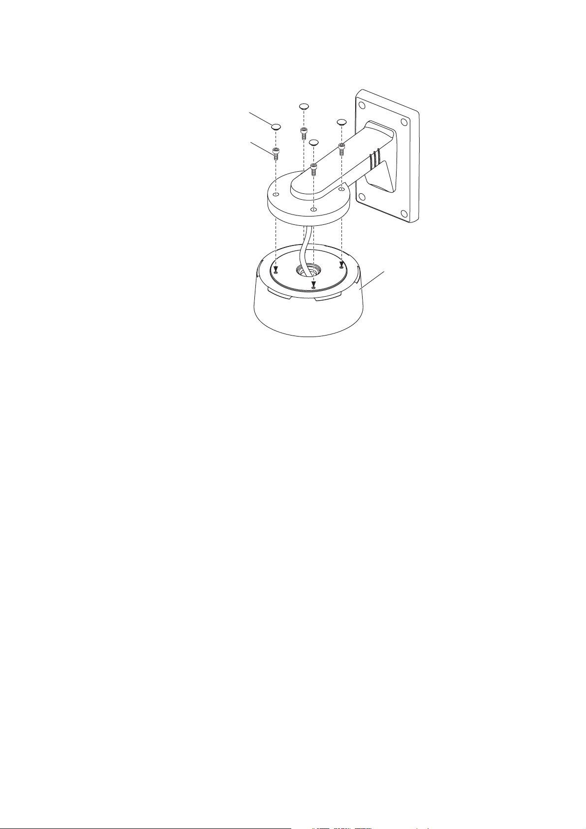
8. Secure the C-CC704's case to the Wall Mounting Bracket with 4 hexagon socket screw, then cover these
screw holes with the waterproof caps as shown in the figure below.
9. Install the camera unit and dome cover to the case.
For the procedures, refer to p. 14 of the C-CC704's instruction manual.
Waterproof cap (accessory)
Hexagon socket screw
(accessory)
C-CC704's case
Page 9

9
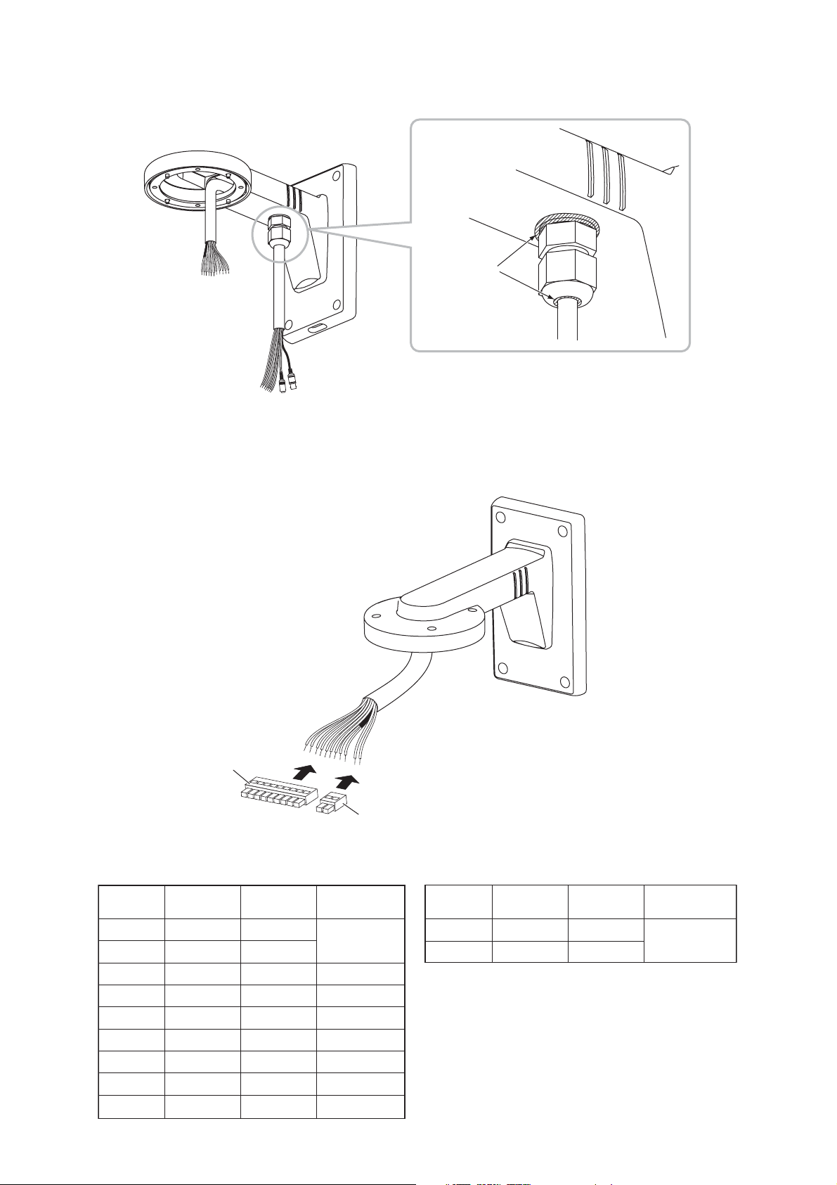
4.2. Open Wiring
1. Run the composite cable supplied with the C-CC704 through the cable bushing supplied with the unit.
Remove the connectors on the end of the composite cable before running the cable through the cable
bushing.
2. Remove the rubber gasket attached to the Wall Mounting Bracket, then attach it to the cable entry hole in
the rear plate.
3. Run the composite cable with a cable bushing mounted from the cable entry hole of the Wall Mounting
Bracket.
Insert
Remove
Rear plate
Remove
Rubber gasket
Attach
Rubber gasket
Page 10
10
4. Secure the cable bushing to the Wall Mounting Bracket, then waterproof 2 points shown in the figure below
with silicone sealant material.
5. Replace the connectors removed in Step 1 on the end of the composite cable.
Note: Pay attention to the correct cable connections. Incorrect wiring at the connectors may cause damage
to the connected equipment.
Sealing points
Input connector
Input/Output connector
Terminal No. Terminal name Cable color
1 VIDEO
2 GND
3 RS485 +
4 RS485
5 GND
6 AL1
7 AL2
8 AL3
9 AL4
Yellow
Shield
Green
-
Blue
White
Brown
Purple
Orange
Gray
Power supply connector
Power supply connector
Terminal
treatment
BNC jack
Bare end
Bare end
Bare end
Bare end
Bare end
Bare end
Bare end
Terminal No. Terminal name Cable color
1 24V AC Red
2 24V AC Black
Terminal
treatment
AC adapter jack
Page 11

11
6. Secure the Wall Mounting Bracket to the wall surface, then waterproof the Wall Bracket's base portion
which contacts the wall surface with silicone sealant material.
7. Connect the composite cable to the external wiring cable.
Note: Seal and insulate each connection of the cable with waterproof tape, then house them in a
waterproof plastic box.
Nut
Spring washer
Plain washer
Waterproofing area
Anchor bolt
( M8, M10, or W3/8 )
e
ac
l surf
al
W
Wall surface
House these in a
waterproof plastic box.
Page 12

Wall mounting bracket: Aluminum, Light gray, paint
Rear plate: Anodized aluminum
118 (W)x 185 (H)x 259 (D)mm (4.65" (W)x 7.28" (H)x 10.20" (D
))
1.0 kg (2.2 lb
)
Finish
Dimensions
Weight
5. SPECIFICATIONS
Note: The design and specifications are subject to change without notice for improvement.
Ver. 1.00
URL: http://www.toa.jp/
8. Secure the C-CC704's case to the Wall Mounting Bracket with 4 hexagon socket screw, then cover these
screw holes with the waterproof caps as shown in the figure below.
9. Install the camera unit and dome cover to the case.
For the procedures, refer to p. 14 of the C-CC704's instruction manual.
• Accessories
Cable bushing ............................................ 1
Hexagon socket screw ............................... 4
Waterproof cap ........................................... 4
Waterproof cap (accessory)
Hexagon socket screw
(accessory)
C-CC704's case
 Loading...