

Page 1
General description
The CB -600 adds to the versatility of the EX-610/620/630 exchanges by offering the function
of making or receiving a telephone call. The device is directly connected to either the telephone
line or to the PBX extension.
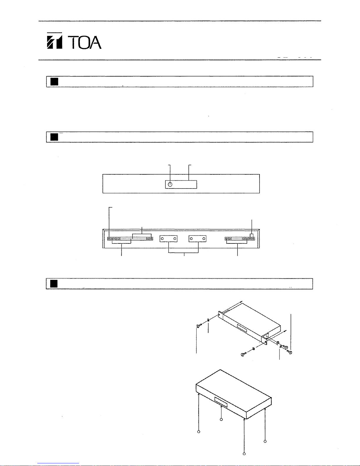
(Front-mounted
facilities)
(Rear-mounted
facilities)
Telephone line terminal Control signal input Intercom line terminal
and output connectors
(CN1,CN2)
Fixing unit
1 . Mounting unit in an equipment rack.
(Exchange is mounted in an equipment rack.)
Attach the accessory rack mounting brackets
to the CB-600 t o mount it in the rack. (See
the figure.)
2. Desk-top application
Attach the accessory rubber foot to each of
4 holes (3mm in diameter) in the bottom
surface.
Installation manual
Telephone line interface
CB-600
Part names
Knob
Cover
Earth terminal
(Be sur e to ground.)
Ringing tone output terminal
Power supply terminal
Fiber washer
M 5 Ra c k mount ing
screw
M3 Washer
M3 Binding head
screw
Page 2
Connection
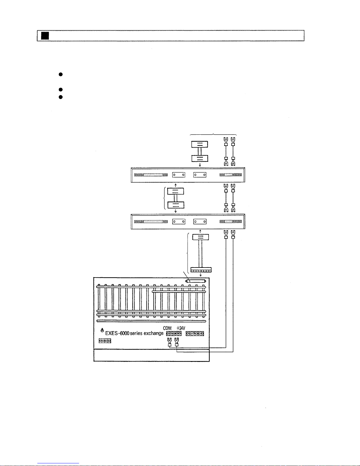
1 . Connecting the control signal input and output connectors and th e power supply.
Use the YR-806 cable (1m in length) for connection between the device and the exchange.
Use the YR-802 cable (40cm) when the unit is placed on the EX-610 or EX-620 exchange.
Use the YR-803 cable when additional units are employed.
Bot h th e C N 1 and CN2 connectors are internally connected in parallel. Use either of the
two.
To other equipment
YR-803
YR-802 or YR-8 06
Interface connector
– 2 –
Page 3
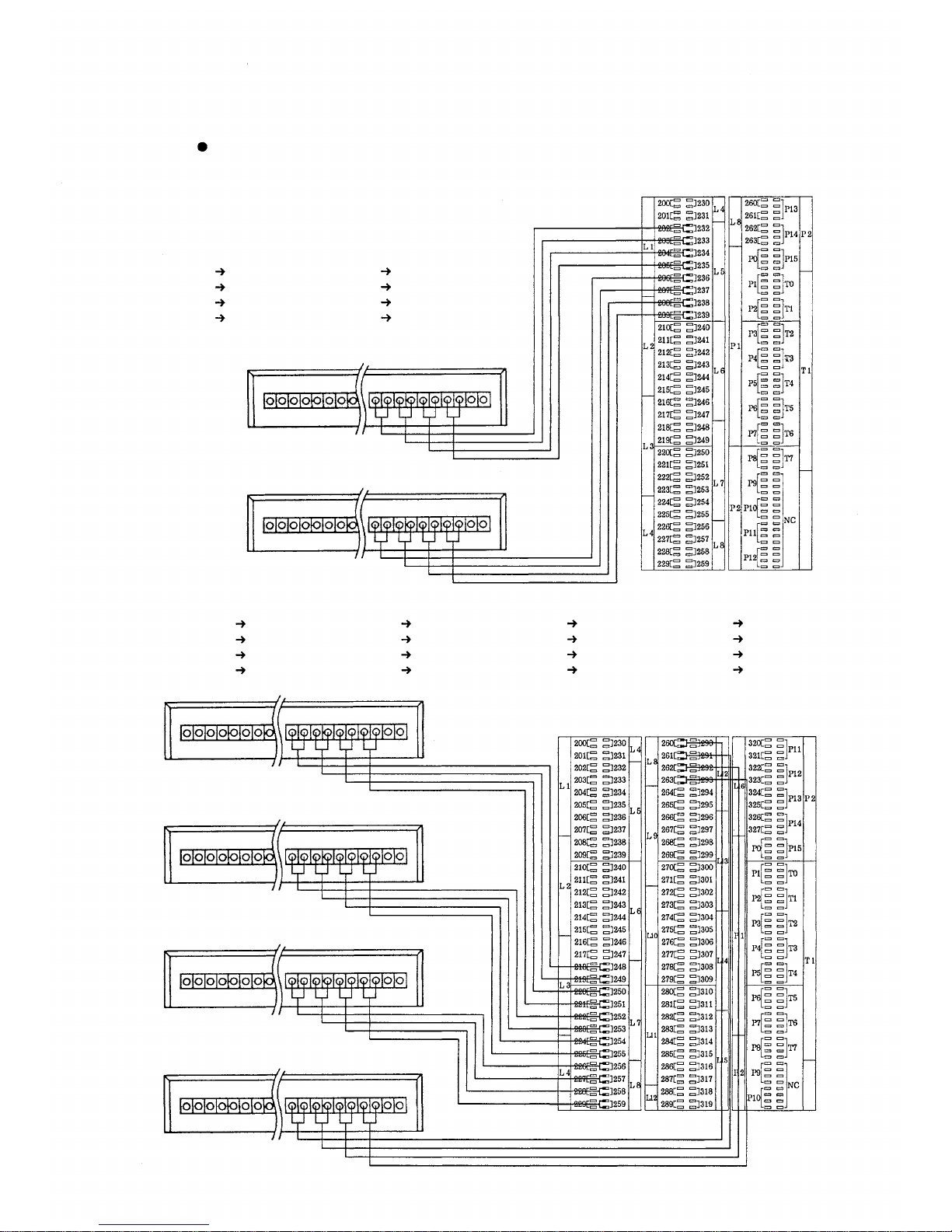
2. Connecting intercom lines
Connect between the intercom line terminals and the terminal box using tw is te d paired
cables. See the figure below.
[EX-610]
1
2
3
4
No.232
No.233
No.234
No.235
( 2nd set)
1
2
3
4
No.236
No.237
No.238
No.239
BX-610
(1 s t set)
(2nd set)
[EX-620/630]
(1st
set)
1
2
3
4
No.248
No.249
No.250
No.251
(2nd s e t )
1
2
3
4
No.252
No.253
No.254
No.255
(3rd s e t )
1
2
3
4
No.256
No.257
No.258
No.259
(4th set)
1
2
3
4
No.260
No.261
No.262
No.263
(1 s t set)
(2nd set)
(3 r d set)
(4th set)
BX-620
(1st set)
– 3 –
Page 4
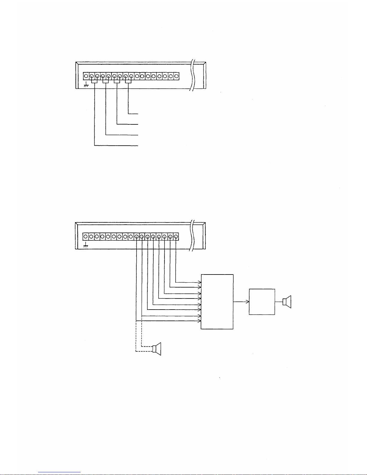
3 . Telephone line connections
Telephone line 4
Telephone line 3
Telephone line 2
Telephone line 1
4 . Terminal connection for ringing tone output
Make connections as shown in the figure below when sounding the ringing tone through an
external speaker.
(This connection is not required when sounding the ringing t one through a station speaker.)
It is also possibl e to directly connect a high-impedance
speaker to these terminals whe n a hi g h sound volume
is not required.
Mixer
amplifier
Power
amplifier
Speaker
– 4 –
Page 5
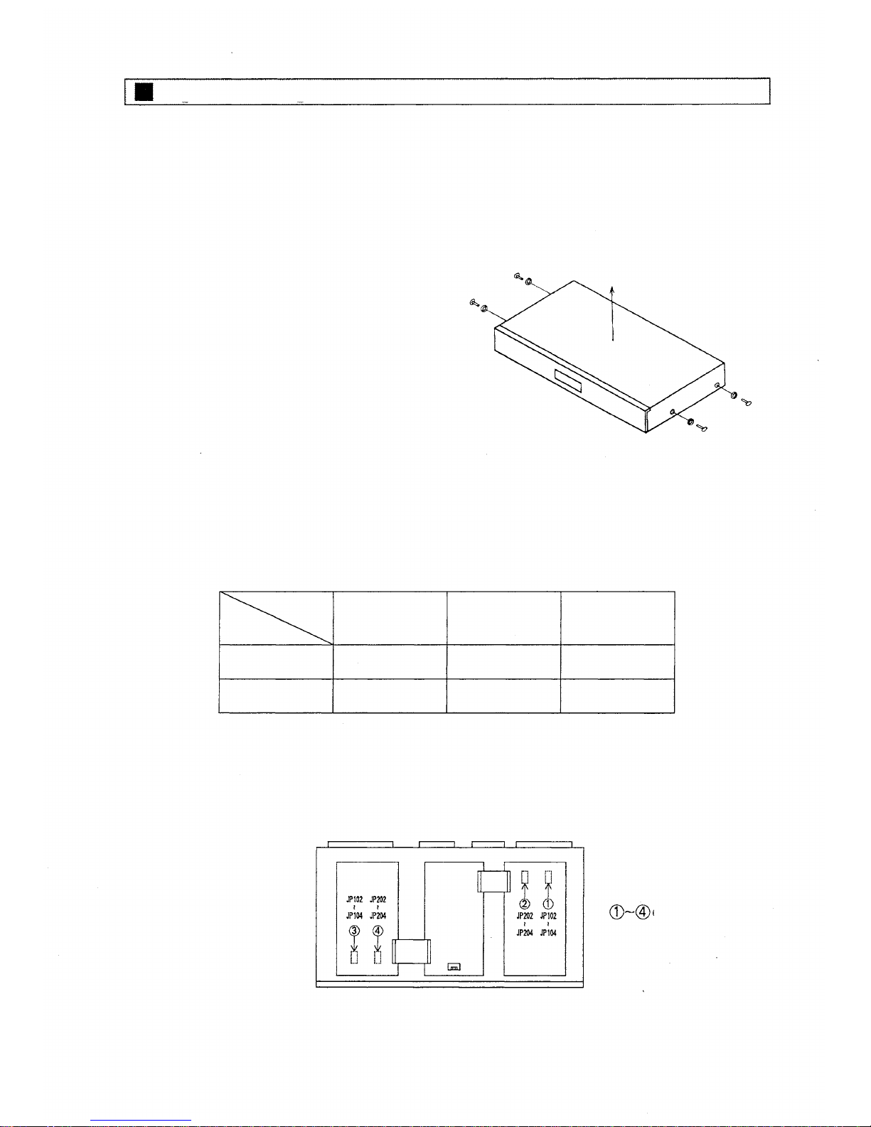
Signal setting
The CB-600 permits independent signal setting pe r telephone line. Follow the proc edures below
to select and set the sdesired signal mode. It is preset for DP signal of 10 pps and for make
ratio of 33 percent when supplied from the factory. (Perform the signal mode setting before
the
final installation or wiring work because the setting requires the removal of the top cover.)
1 . Remove side plate screws(four places).
2. Detach the top cover.
3 . Set the jumper wires according to the table below.
Dial speed
JP102/JP202
10pps
20pps
Signal type
JP103/JP203
PB (DTMF)
DP
Ma ke ratio
JP104/JP204
40%
33%
(Jumper w ire position)
Jumper wir e numbers
correspond to the
respective telephone line
numbes.
(Front)
State of
jumper wire
Connected
Disconnected
– 5 –
Page 6

Channel selector setting
Pull the front-mounted release kno b towards you and remove the cover, and the channel s e l e c t or
can be seen. Set the switch as shown in the figure below.
For the 1st set
For the 3rd set
For the 2nd set
For the 4th set
Channel selector
Adjusting receiving sound volume
Th e receiving sound volume can be adjusted in 3d B step b y switching SW101 and SW201 shown
in the figure below.
(Rear)
(Front)
indicate
the corresponding circuit
numbers.
The numbers
– 6 –
Page 7

Adjusting receiving sound volume
The receiving sound volume can be adjusted each telephone line by the semi-fixed volume
controls provided at both sides of the channel selector. When the receiving sound volume
is decreased by the line loss etc., adjust the semi-fixed volume controls by a flat tip
screwdriver so as to obtain optimum sound volume. The telephone line numbers to be
used correspond to the speech link numbers as shown the table below.
Telephone
line
No.
Speech link No.
1st set
1
0
2
1
3
2
4
3
2nd set
1
4
2
5
3
6
4
7
3rd set
1
8
2
9
3
10
4
11
4th set
1
12
2
13
3
14
4
15
For telephone line 1
For telephone line 4
For telephone line 2
For telephone line 3
– 7 –
Page 8

Station
No.200
programming
Perform the
station
No.200
programming
with
the following chart.
For details, refer to "Installation Handbook of CP-66".
<CB- 600 Telephone line allocation> (FUNCTION CODE 25)
2. Re-start at Step 1 when mis-dialling
occurs. (All other registrations remain
valid.)
Confirmation
tone will be
heard.
CB-600 telephone line allocation
Touch
Function Code
Number of digits for trunk seizure
operation and incoming call pick up
operation?
Single digit
Double digit
Confirmation
tone
Repeat
Confirmation
tone
Repeat
Registered?
Yes.
Return
NOTES
1 . To clear registration on all rented lines.
3. Telephone line No. :00~07 for EX-610
4. Line No. 0 is impossible to use w h e n CB-600
is used in pager call.
5. If the station does not need to receive an
incoming telephone call, the trunk seizure
operation and incoming cal l pick up operation
are identical.
Touch
Touch
No.
– 8 –
Page 9

<CB-600 Telephone line allocation to station group> (FUNCTION CODE 27)
NOTES
1. To clear registrations on all telephone lines.
(Confirmation tone will be heard)
2. Re-start at Step 1 when mis-dialling occurs. (Al l other registrations remain valid.)
3. Switch C-1 must be "ON" to employ this function.
4. Also dial 2 digits (01 to 07) to programme the system having paging zones 1 to 7.
5. Line No. 0 is impossible to use when CB-600 is used in pager call.
6. Zone numbers of each exchange in Tie-line system.
Exchange "A"
Exchange "B"
Exchange "C"
7. Telephone line No. 0 0 ~ 1 5 (00~07 fo r E X- 610).
8. Mode No.
0 : External ringer mode
1 : Station paging pre-announcement tone mode
No. 01~15
No.
16~30
No. 31~45
CB-600 Telephone line allocation to station group.
Touch
Function Code
Step
Touch
Zone line
1st
line
Last line
Mode
Touch
Confirmation tone
Registered?
Touch
– 9 –
Page 10

<Stations Allowed Access to incoming phone call> (FUNCTION CODE 31)
NOTES
1 . To allow the stations to have this function,
Touch
Be sure to depress the
(Confirmation tone will be heard.)
key steadily.
2. To release at one time the data programmed into all the stations for this function,
(Confirmation tone will be heard.)
3. Re-start at Step 1 when mis-dialing occurs. (A ll other registrations remain val id. )
4. Dial 2 digits when programming the station for 2-digit dialling. Dial last 3 digits for
station programming when 4-digit dialling is employed.
Stations Allowed Access to outgoing phone call
Function Code
New Registration?
Station No. allowed to make outgoing telephone call
Confirmation
tone
New Registration finished?
Release?
Station No. allowed to make outgoing telephone call
Release finished?
Return
– 10 –
Page 11

<Stations Allowed Access to incoming phone call> (FUNCTION CODE 32)
NOTES
1. To a llow the stations to have this function,
Touch
Be sure to depress the
(Confirmation tone will be heard .)
key steadily.
2. To release at one time the dat a programmed into all the stations for this function,
Touch
(Confirmation tone will be heard.)
3. Re-start at Step 1 when mis-dialing occurs. (All other registrations remain valid.)
4. Dial 2 digits when programming the station for 2-digit dialling. Dial last 3 digits for
station programming when 4-digit dialling is employed.
– 11 –
Page 12

<PAGING ZONE> (FUNCTION CODE 70)
NOTES
1 . To release at one time the data programmed into all the Zones for this function,
(Confirmation tone will b e heard)
Touch
2. Re-start at Step 1 when mis-dialling occurs. (All other registrations remain valid.)
3. Switch C-1 must be "ON" to employ this function.
4. Also dial 2 digits (01 to 07) to programme the system having paging zones 1 to 7.
Ex. Zone No. 7
5. When "Paging Response Without Zone Number" mode
by the DIP Switch SW-C-7, this registration is essential.
6. When "Paging Priority" function is adopted by the DIP Switch SW-C-3, this registration
should be made f or ea ch Paging Zone of No. 01 to No. 31.
7. The programming is required for zones 01 to 31 when the telephone line interface is
in
use.
8. Zone numbers of each exchange in Tie-line system.
Exchange "A"
Exchange "B"
Exchange "C"
is selected
9. Dial 2 digits when programming the station for 2-digit dialling. Dial last 3 digits for
station programming when 4-digit dialling is employed.
No.
01~15
No.
16~30
No. 31~45
Establishment of each paging zone
Touch
Function Code
Paging Zone No.
(01~,16~,31~)
First Station No.
of the Zone
Last Station No.
of the Zone
Paging Zone No.
(01~,16~,31~)
First Station No.
of the Zone
Last Station No.
of the Zone
Confirmation tone
New Registration finished?
Return
– 12 –
Page 13

Specifications
Accessories
Rack mounting bracket
Rack mounting screw (M5 x 12 tapping screw)
Fiber washer
Binding head screw (M 3 x 6)
M3 washer
Rubber foot
2
2
2
4
4
4
Telephone line capacity
Maximum number of units connectable in parallel
Dial signal
Ringing tone output
Power voltage
Current consumption
Ambient temperture
Dimensions
Weight
4 lines
4(2 for EX-610)
DP (10/20pps changeable)
PB (switchable per circuit)
+ 5dBm (600 , unbalanced)
DC + 24V
(20V ~ 28V)
Maximum 100mA
0°C~40°C
432(W) x 44.5(H) x 292(D)mm
3.3kg
– 13 –
Page 14

TOA Corporation
KOBE, JAPAN
133-06-161-5A
 Loading...