

Page 1
OPERATING INSTRUCTIONS
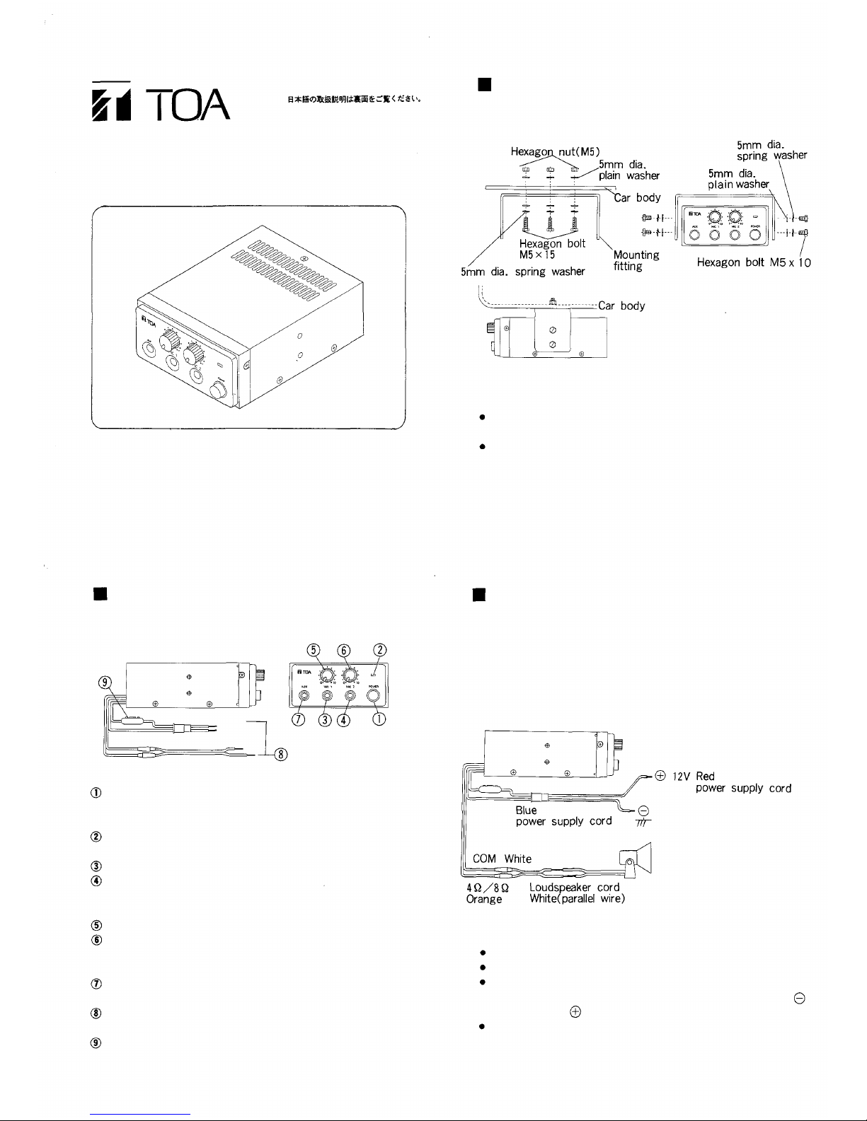
Mounting Method
CAR AMPLIFIER
CA-200
Please follow the instructions in this manual to obtain the
optimum results from this unit.
We also recommend that you keep this manual handy for future
reference.
Install so as to facilitate the dissipation of heat from the
radiator of the amplifier.
Do no t use M5 × 15 bolts where M5 × 10 bolts are to be installed.
Otherwise parts inside the amplifier may be damaged.
Fasten the microphone holder with self tapping screws (M4 x 16)
where the microphone can be handled easily.
Name and Function of Each Part
Power Switch (POWER)
To power on the amplifier, depress the power switch, and
to power off the amplifier, depress the switch again.
Power Lamp
The light comes on when the power supply is switched on.
Microphone 1 Input Ja ck (MIC 1 )
Microphone 2 Input Ja ck (MIC 2)
Plug in the supplied microphone or other Low impedance
microphone.
Microphone 1 Volume Control Knob
Microphone 2
Volume Control Knob
Adjust these knobs to control the volume of microphones
plugged in "MIC 1" or "MIC 2" respectively.
Auxiliary Input Jack (AUX)
Connect a tape recorder or a radio to this jack.
Power and Loudspeaker Cords
Cords for connecting power supply and the loudspeaker.
Fuse holder
Be su re t o u se a fus e of the specified ty pe and rating. Use of
other fuse than specified may cause equipment breakdown.
Connection
Connect the power supply and the loudspeaker according to
the following diagram.
Not usable for cars using 24V battery.
Not usable for cars using positive grounding.
Do not mistake the positive and the negative of the power
supply cord in connection. If the blue power supply cord
is connected to by mistake, the amplifier may be damaged.
Consult our distributor for the output of the amplifier, the
input capacity of the loudspeaker and the connection of two
or more loudspeakers.
Connect to the positive
electrode of the battery or
the power supply cord of the
radio.
Connect to a metal part
of the car positively.
Page 2
Operation
1 . Depress the power switch , then power is supplied and
the power lamp lights up.
2. Plug the microphone in the microphone input jack
3. Adjust the microphone 1 volume control to an adequate
volume.
4. To use other microphone, plug the microphone in the
microphone 2 input jack and adjust the volume by the
microphone 2 volume control knob
Up to tw o microphones can be used at a time.
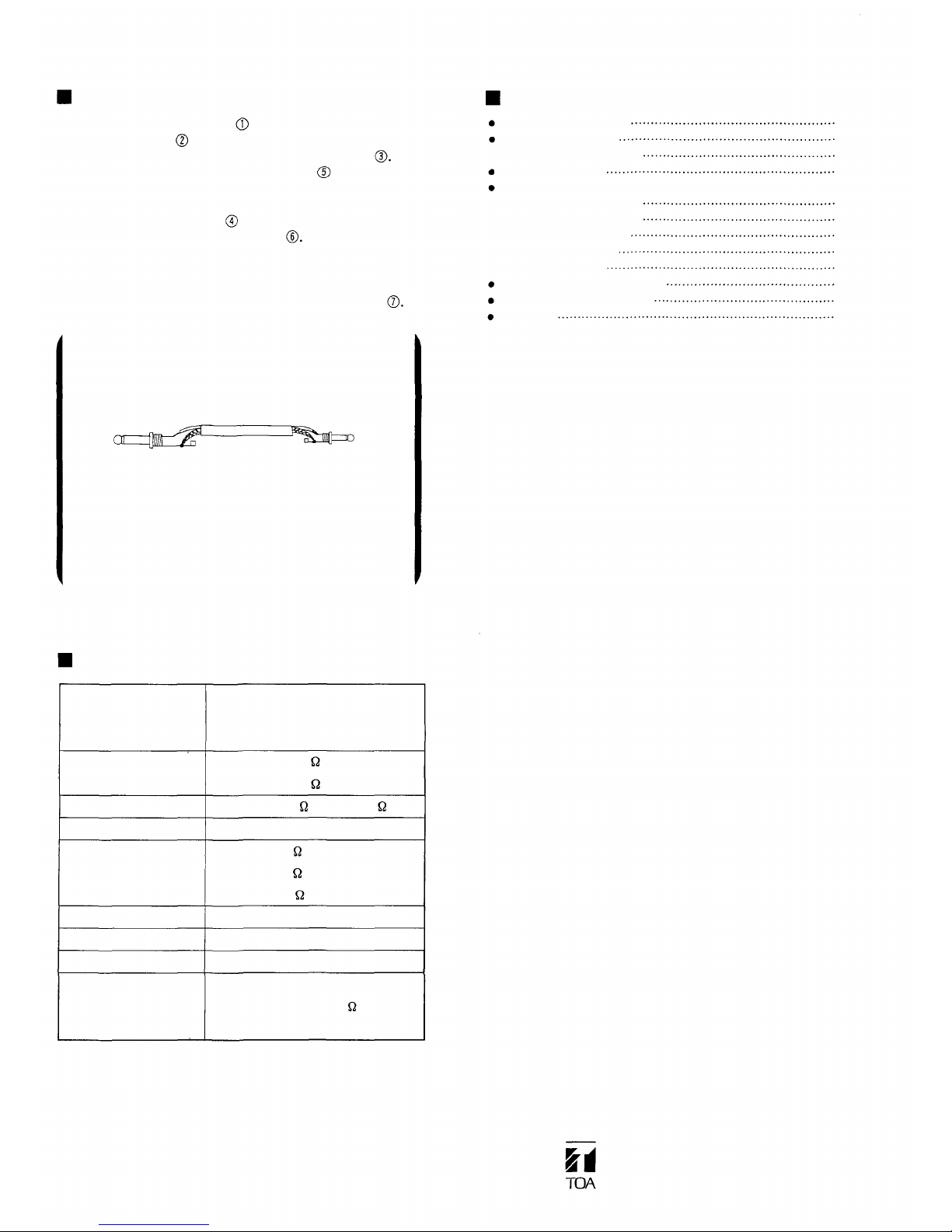
5. To amplify the output of a tape recorder or a radio,
connect the earphone terminal or the line out terminal of
the tape recorder or the radio to the auxiliary input j ack
To connect the tape recorder or the radio to the
amplifier, use a phone plug - to - mini plug cord
obtainable at a store or the cord illustrated below.
Phone plug
Shielded wire
Mini plug
Solder the shield wire to the terminals of the phone
plug and the mini plug so as not to contact other
terminals.
Consult our distributor for detail.
Dynamic microphone
Microphone holder
· Fixing screw (4x16)
Mounting bracket
Mounting screws
· Hexagon bolt (5 x 1 5)
· Hexagon bolt (5 x 10)
· Hexagon nut (M5)
· Spring washer 5
· Plain washer 5
Power supply cord (1.5m)
Loudspeaker cord (0.3m)
Fuse 4 A
Standard Accessories
2
1
3
4
3
7
10
1
1
1
Specifications
Power requirement
Current consumption
Rated power output
Distortion
Inputs
Frequency response
Dimensions
Weight
Accessory microphone
Standard voltage : 13.8 VDC
Allowable range : 10 - 16 VDC
(using
12 V
battery)
1. 8 A or less (8 / 10 W output)
2.8 A or les s (4 /20 W output)
10W at 8 , 20W at 4
Less than 5% (at 1kHz rated output)
MIC 1 : 600 , 4 mV
MIC 2 : 600 , 4 mV
AUX : 10k , 500 mV
10 0 H z -10kHz±3dB
120 (W) × 60(H) × 170(D)mm
0.7 kg (without accessories)
Uni-directional dynamic type with talk switch
Impedance: 600
Sensitivity : -73 dB ±3 dB
TOA Corporation
533-01-026-20
1
1
Page 3

CA - 200
*Please see the reverse side for English manual.
Page 4

TEL.
0797-72-7567
FAX.
0797-72-1090
0120-108-117
 Loading...