

Page 1
M-9000
Digital Matrix Mixer
DESCRIPTION
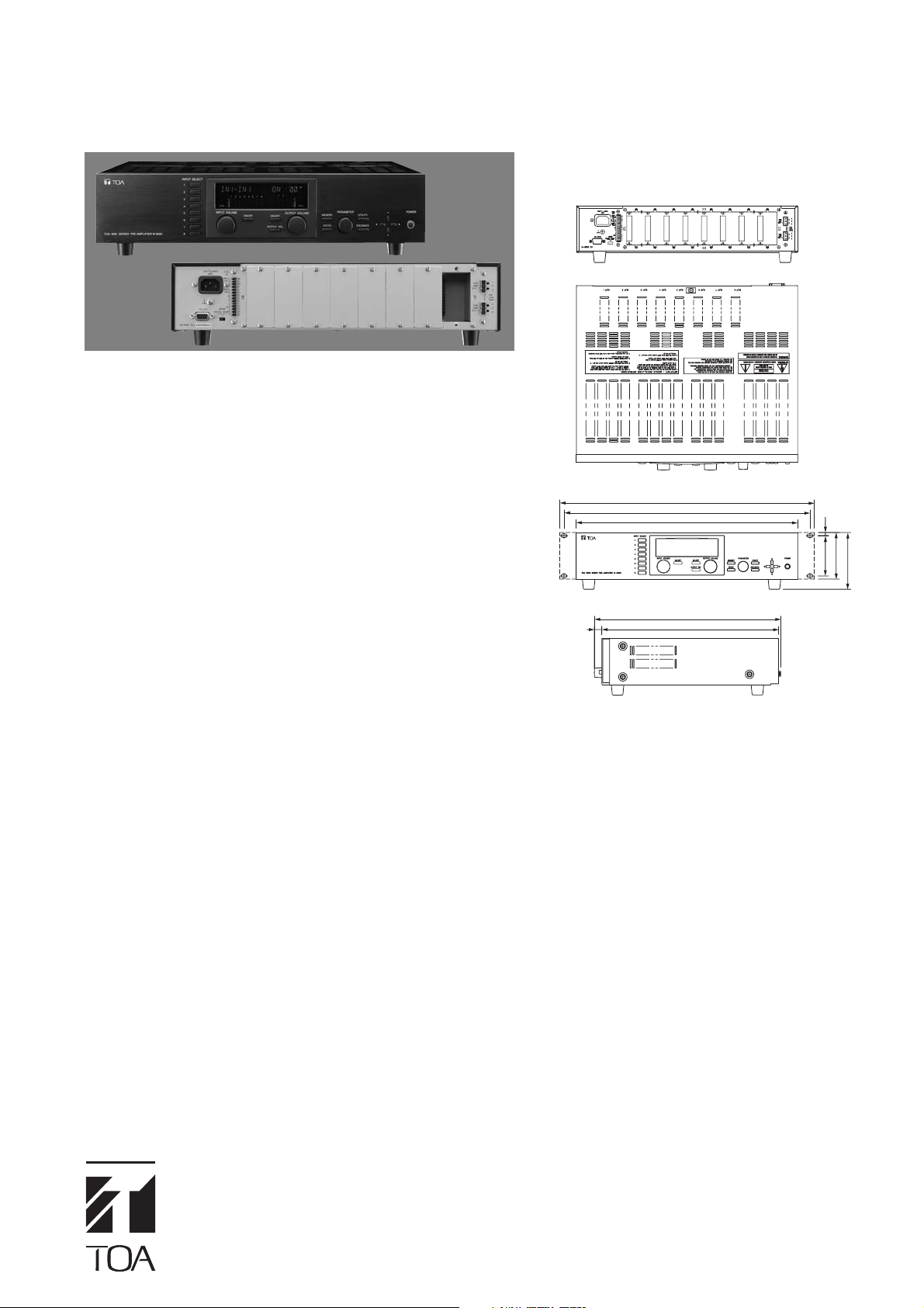
The TOA M-9000 Digital Matrix Mixer features a compact design that
fits in a two rack space package. The versatile new mixer is ideal for
multi-zone paging, music distribution and room-combining applications.
The M-9000 includes eight module ports allowing designers to easily
configure custom systems with up to eight mic/line inputs and eight
outputs. The M-9000 chassis has two channels of built-in digital signal
processing (DSP) with ten band parametric EQ, compressor, eight
level ducking and more. Input and output modules provide additional
DSP.
Two discrete operation modes, "Mixer" and "Matrix", allow the M-9000
to be used in both simple mixing and complex multi-zone paging
applications. Versatile features include telephone zone paging,
automatic microphone mixing and ambient noise control.
APPEARANCE AND
DIMENSIONAL DIAGRAM
Rear View
Top View
482
466
420
Front View
14
353
335
6.1
76.2
88.4
107.6
SYSTEM FEATURES
■ Modular Digital Matrix Mixer for a multitude of applications
including audio-visual, zone paging, room combining and many more.
■ Dual Modes (Mixer and Matrix) — two separate feature sets to suit
both simple mixing and complex multi-zone distribution applications.
■ Easy to Configure and Operate
■ Exceptional Audio Quality
• 24-bit, 48 kHz sampling
•Low Distortion - 0.008%
■ Modular System— up to 8 mic/line inputs and 8 outputs.
■ Dual Channel Digital Signal Processor (DSP):
• 10-band parametric EQ
•High and low pass filters
•Compressor
• Loudness contour
•Bass and treble
•Delay (Mixer mode)
•TOA Speaker EQ presets
•Additional DSP included on D-001T, D-001R and T-001T modules
■ Telephone Zone Paging— access up to eight zones with optional
ZP-001T module
■ Ambient Noise Control— automatically increase or reduce output
levels in response to changes in ambient noise.
■ Multi-function Display allows programming and operation without
a PC.
■ Rack-mount Kit Included (2RU)
Side View
Flexible Remote Control
Two Remote Volume Control Terminals
• Assignable to any input or output channel
• Control with 10k ohm linear potentiometer, 0-10 VDC or optional
ZM-9001/ZM-9002 remote panels
• Assign remote volume control to background music (Priority 8)
inputs without affecting paging input volume
Four Control Inputs (expandable to twelve with C-001T module)–
programmable to activate Memory, Volume Up/Down, Mute, Power
On/Off, Emergency Mute
• ZM-9003 can also be connected.
Four Control Outputs (expandable to twelve with C-001T module) –
programmable to activate external relays synchronized with Memory,
Channel On/Off and Power On/Off
RS-232 Port
• Control protocol available for external devices (see protocol for
controllable parameters)
• AMX and Crestron control modules available
Additional Features
Software Utility for saving unit parameters to PC, updating unit
firmware, virtual control activation and status indication
MS Excel Programming Templates – use Microsoft(R) Excel for off-
site programming
Keylock Security sets password-protected access to Input,
Output, Utility & Power functions
Input and Output Metering (D-001 module(s) required for input
metering)
Alphanumeric Channel and Memory Naming
Power On Memory sets the Event/Scene selected when unit
powers up
Detachable AC Cable
Page 2
M-9000
Digital Matrix Mixer
SPECIFICATIONS
Power Requirement AC mains, 50/60 Hz
Power Consumption 40W
Audio Input Max. 8 channels, modular construction (modules optional)
Audio Output Preamplifier output 1, 2: 0 dB*, 600 ohms, balanced, removable terminal block (3 pins)
Module Slot Analog input (slot 1 – 8): –10dB*, 10 k ohms, unbalanced
Digital Audio Signal Reference Level –20dBFS
Frequency Response 20 – 20,000 Hz, +1, –3 dB
Total Harmonic Distortion 0.008% (at 22 kHz LPF, 1 kHz, +10 dBV output)
S/N Ratio At Input short, 20 – 20,000 Hz, ALL FLAT or OFF setting
Crosstalk Over 64 dB (at 20 kHz)
Tone Control Bass: +/–12 dB (at 100 Hz), Treble: +/–12 dB (at 10 kHz)
Parametric Equalizer 10 bands, Freq: 20 – 20,000Hz, 31 steps, Various range: +/–12 dB, Q: 0.3 – 5
Speaker Equalizer 15 (compatible with TOA speakers only)
High-pass Filter –12 dB/oct, Variable frequency range: 20 – 400 Hz, 14 steps
Low-pass Filter –12 dB/oct, Variable frequency range: 4,000 – 20,000 Hz, 8 steps
Compressor Depth: 1 – 5
Delay 0 – 40 ms (1 ms steps), maximum 40 ms (CH1 + CH2) (Mixer mode only)
Scene/Event Memory 32
Operation Mode Matrix mode/Mixer mode (selector switch)
Auxiliary Function Key lock function
Control Input/Output RS-232C*
Operating Temperature –10°C to 40°C
Operating Humidity 35% to 80% RH (no condensation)
Finish Panel: Aluminum, hair-line, black, Case: Surface-treated steel plate, black paint
Dimensions 420 (W) × 107.6 (H) × 353 (D) mm
Weight 6 kg (without modules)
Accessory Power cord (2m) × 1, Rack Mounting bracket × 2, Bracket mounting screw × 4, Blank panel × 7, Blank panel mounting screw × 14,
* 0dB = 1V
2
Allowing it to be controlled by a control system such as AMX and Crestron through RS-232C port.
*
Notes: AMX is a tradmark of AMX Corporation. Crestron is a tradmark of Crestron Electronics. Inc.
Digital input (slot 1– 4): 24 bit/48kHz
MIX output (slot 1 – 8): -14dB*, 330 ohms (CH 1 prefader output), unbalanced
Digital output (slot 5 – 7): 24 bit/48kHz
Power supply (slot 1 – 8): 24V, -24V, :6V DC
Output volume min.: 90 dB
Output volume max.: 61 dB (input 1 vol.: 0 dB, other inputs: OFF)
2
, D-sub connector (9P, female)
Control input: 4 inputs, no-voltage make contact input, open voltage: 3.3 V DC, short-circuit current: under 1 mA, removable terminal block (14 pins)
Control output: 4 outputs, open collector output, withstand voltage: 27 V DC, control current: 50 mA, removable terminal block (14 pins)
Remote volume: 2 channels, connect a 10 k ohms/linear taper variable resistor or input the DC voltage of 0 to +10V, removable terminal block (14 pins)
Removable terminal plug (3 pins) × 2, Removable terminal plug (14 pins) × 1, CD-ROM × 1, Start guide × 1
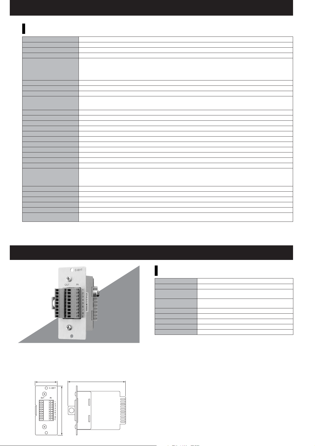
C-001T
The C-001T is Control I/O expansion module designed for use
with the M-9000 and can provide up to 8 channels each of input
and output expansion. Since the main unit has 4 preinstalled
inputs and outputs each, the control input and output can be
expanded to up to 12 channels each when the C-001T is used.
35
Control Input/Output Module
91.5
SPECIFICATIONS
Power Requirement 6 V DC
Current Consumption 15 mA
Control Input 8 channels, open voltage: 3.3 V DC, short-circuit
Control Output
control current: max. 50 mA, removable terminal block (9 pins)
Operating Temperature -10°C to +40°C
Finish Panal: Aluminum, hair-line
Dimensions 35 (W) × 78 (H) × 91.5 (D) mm
Weight 62 g
Accessory Removable terminal plug (9 pins) × 2, Module mounting screw × 2
current: under 1 mA, removable terminal block (9 pins)
8 channels, open collector output, withstand voltage: 27 V DC,
78
Unit: mm
Page 3
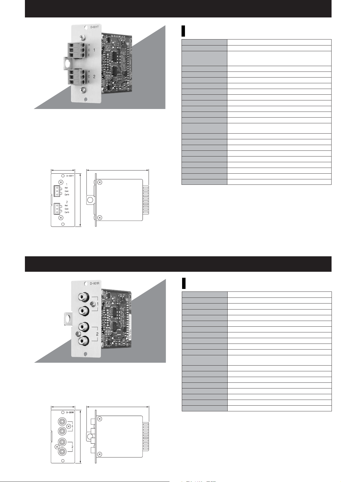
D-001T
The D-001T is a plug-in module designed for use with the
M-9000 and can provide two independent balanced inputs. The
D-001T can handle signals ranging from microphone level to line
level by controlling their input sensitivity in 9 increments from
-60dB to -10dB.
Phantom power (+24V) can be supplied for condenser
microphone use. The D-001T can process effect for TONE/EQ/
COMPRESSOR to two inputs independently.
35 91.5
Dual Mic/Line Input Module with DSP
SPECIFICATIONS
Power Requirement +24 V DC, -24 V DC, +6 V DC
Current Consumption 20 mA (at +24 V DC), 20 mA (at -24 V DC), 60 mA (at +6 V DC)
Input 2 channels, 3 k ohms (when the phantom power is ON)/
Input Sensitivity -60, -54, -48, -42, -36, -30, -24, -18, -10 dB* (selectable)
Frequency Response 20 – 20,000 Hz, +1, -3 dB
THD + N
Input Equivalent Noise Under -112 dB (at 20 – 20,000 Hz BPF, Input short, Input sensitivity: -60 dB)
S/N Ratio Over 73 dB (at 20 – 20,000 Hz BPF, Input short, Input sensitivity: -10 dB)
Cross Talk Over 75 dB (at 20 kHz, Input sensitivity: -10 dB)
CMRR Over 62 dB (at 1 kHz, Input sensitivity: -60 dB)
A/D Converter 24 bit ∆∑ADC
Sampling Frequency 48 kHz
Tone Control Bass: ±12 dB (at 100 Hz), Treble: ±12 dB (at 10 kHz)
Parametric Equalizer 10 bands, Frequency: 20 – 20,000 Hz, 31 steps,
Variable range: ±12 dB, Q: 0.3-5
High-pass Filter -12 dB/oct, Variable frequency range: 20 – 400 Hz, 14 steps
Low-pass Filter -12 dB/oct, Variable frequency range: 4,000 – 20,000 Hz, 8 steps
Compressor Depth: 1 – 5
Phantom Power +24 V DC
Operating Temperature -10°C to +40°C
Finish Panel: Aluminum, hair-line
Dimensions 35 (W) × 78 (H) × 91.5 (D) mm
Weight 82 g
Accessory Removable terminal plug (3 pins) × 2, Module mounting screw × 2
*0 dB = 1 V
10 k ohms (when the phantom power is OFF),
electronically-balanced, removable terminal block (3 pins)
0.008% (at 1 kHz, 20 – 20,000 Hz BPF, Input sensitivity: -10 dB)
78
Unit: mm
D-001R
The D-001R is a line input plug-in module designed for use with
the M-9000. It has 2-channel unbalanced input of RCA jacks.
Input signals to both channels are mixed together. The D-001R
can process effect for TONE/EQ/COMPRESSOR to two inputs
independently.
35 91.5
Line Input Module with DSP
SPECIFICATIONS
Power Requirement +24 V DC, -24 V DC, +6 V DC
Current Consumption 20 mA (at +24 V DC), 20 mA (at -24 V DC), 60 mA (at +6 V DC)
Intput 2 channels, 2 RCA/ch mixed, 10 k ohms, unbalanced, RCA pin jack
Intput Sensitivity -60, -54, -48, -42, -36, -30, -24, -18, -10 dB* (selectable)
Frequency Response 20 – 20,000 Hz, +1, -3 dB
THD + N
0.008% (at 1 kHz, 20 – 20,000 Hz BPF, Input sensitivity: -10 dB)
S/N Ratio Over 70 dB (at 20 – 20,000 Hz BPF, Input short, Input sensitivity: -10 dB)
Cross Talk Over 75 dB (at 20 kHz, Input sensitivity: -10 dB)
A/D Converter 24 bit ∆∑ADC
Sampling Frequency 48 kHz
Tone Control Bass: ±12 dB (at 100 Hz), Treble: ±12 dB (at 10 kHz)
Parametric Equalizer 10 bands, Frequency: 20 – 20,000 Hz, 31 steps,
Variable range: ±12 dB, Q: 0.3 – 5
High-pass Filter -12 dB/oct, Variable frequency range: 20 – 400 Hz, 14 steps
Low-pass Filter -12 dB/oct, Variable frequency range: 4,000 – 20,000 Hz, 8 steps
Compressor Depth: 1 – 5
Operating Temperature -10°C to +40°C
Finish Panel: Aluminum, hair-line
Dimensions 35 (W) × 78 (H) × 91.5 (D) mm
Weight 82 g
Accessory Module mounting screw × 2
*0 dB = 1 V
78
Unit: mm
Page 4

T-001T
The T-001T is a plug-in module designed for use with the M-9000
and provide two independent balanced outputs. It can drive load
of 600 ohms up to +16dB. It can process effect for TONE/EQ/
COMPRESSOR to two inputs independently.
35 91.5
Dual Line Output Module with DSP
78
SPECIFICATIONS
Power Requirement +24 V DC, -24 V DC, +6 V DC
Current Consumption 35 mA (at +24 V DC), 35 mA (at -24 V DC), 60 mA (at +6 V DC)
Output 2 channels, max. +20 dB* (at 10 k ohms load), 600 ohms,
electronically-balanced, removable terminal block (3 pins)
Frequency Response 20 – 20,000 Hz, +1, -3 dB
THD + N
0.005% (at 1 kHz, 20 – 20,000 Hz BPF, 5 V output, 10 k ohms load)
S/N Ratio Over 73 dB (at 20 – 20,000 Hz BPF )
Residual Noise Under -91 dB (at 20 – 20,000 Hz BPF, VOL: -70 dB)
Cross Talk Over 87 dB (at 20 kHz)
D/A Converter 24 bit ∆∑ADC
Sampling Frequency 48 kHz
Tone Control Bass: ±12 dB (at 100 Hz), Treble: ±12 dB (at 10 kHz)
Parametric Equalizer 10 bands, Frequency: 20-20,000 Hz, 31 steps,
Variable range: ±12 dB, Q: 0.3-5
Speaker Equalizer 15 (compatible with TOA speakers only)
High-pass Filter -12 dB/oct, Variable frequency range: 20 – 400 Hz, 14 steps
Low-pass Filter -12 dB/oct, Variable frequency range: 4,000 – 20,000 Hz, 8 steps
Compressor Depth: 1-5
Delay 0-40 ms (1 ms step), maximum 40 ms (CH 1 + CH2), mixer mode only
Operating Temperature -10°C to +40°C
Finish Panel: Aluminum, hair-line
Dimensions 35 (W) × 78 (H) × 91.5 (D) mm
Weight 82 g
Accessory Removable terminal plug (3 pins) × 2, Module mounting screw × 2
*0 dB = 1 V
Unit: mm
SS-9001
The SS-9001 is a speaker selector used in conjunction with the
M-9000. It outputs 2 input signals to 4 different zones.
Speaker Selector
photo: 70 V line model
SPECIFICATIONS
Power Requirement Supplied from the optional AD-246 AC adapter or an
external 24 V DC/200 mA power supply.
Current Consumption 120 mA
Control Signal No-voltage make contact input (polarized),
open voltage: 24 V DC, short-circuit current: 3 mA
Control Power 240 W or less (70 V/100 V line)
Speaker Terminal Removable terminal block (2 pins)
Control Terminal Removable terminal block (10 pins)
Operating Temperature -10°C to +40°C
Finish Case: Surface-treated steel plate
Dimensions 112 (W) × 197 (H) × 30 (D) mm
Weight 530 g
Accessory Removable terminal plug (2 pins) × 6,
Removable terminal plug (10 pins) × 1, Cord clamp × 1, Mounting screw × 4
Option AC adapter: AD-246
157
1
30
18 1870
112
177
10
197
Unit: mm
Page 5

AN-001T
Ambient Noise Controller Module
The AN-001T is a plug-in module of 2-channel ambient noise
detector designed for use with the M-9000.
It automatically adjusts the output volume in response to the
change of ambient noise level. The AN-001T can handle input
signals from microphone level (-60dB) to line level (-10dB) by
controlling the gain in 9 steps.
Phantom power (+24V) can be supplied for condenser microphone
use.
35 91.5
SPECIFICATIONS
Power Requirement +24 V DC, -24 V DC, +6 V DC
Current Consumption 20 mA (at +24 V DC), 20 mA (at -24 V DC), 60 mA (at +6 V DC)
Input Sensor input (Ambient noise sensor microphone input):
2 channels, 3 k ohms (when the phantom power is ON)/10 k ohms
(when the phantom power is OFF), electronically-balanced,
removable terminal block (3 pins)
Input Sensitivity -60, -54, -48, -42, -36, -30, -24, -18, -10 dB* (selectable)
Phantom Power +24 V DC
A/D Converter 24 bit ∆∑ADC
Sampling Frequency 48 kHz
Ambient Noise Control Sensor input reference level adjustment function
Function Maximum output signal level control: -15 to 0 dB
Minimum output signal level control: -18 to -3 dB
Sample time setting: 10 s, 15 s, 20 s, 30 s, 1 min, 2 min, 3 min, 5 min
Gain ratio setting (Ambient noise: Output signal level):
6:3, 5:3, 4:3, 3:3, 3:4, 3:5, 3:6, 6:-3, 5:-3, 4:-3, 3:-3, 3:-4, 3:-5, 3:-6,
Operating Temperature -10°C to +40°C
Finish Panel: Aluminum, hair-line
Dimensions 35 (W) × 78 (H) × 91.5 (D) mm
Weight 82 g
Accessory Removable terminal plug (3 pins) × 2, Module mounting screw × 2
Option Ambient Noise Sensing Microphone: AN-9001
*0 dB = 1 V
78
Unit: mm
AN-9001
Ambient Noise Sensing Microphone
The AN-9001 is an electret condenser microphone designed for
ambient noise detection. It is used in conjunction with the
AN-001T Ambient Noise Controller Module.
It can be mounted in an American standard 1-gang electrical box
in the ceiling or wall.
SPECIFICATIONS
Type Electret condenser microphone
Phantom Power 14-26 V DC
Current Consumption 7 mA (at 24 V DC)
Directivity Omnidirectional (hemispherical)
Impedance 200 ohms
Rated Sensitivity -5 dB (1 kHz, 0 dB = 1 V/Pa)
Frequency Response 100-10,000 Hz
Output Terminal Removable terminal block (3 pins)
Operating Temperature -10°C to +40°C
Finish Panel: ABS resin, white
Frame, Case: Surface-treated steel plate
Dimensions ø130 × 37 (D) mm
Weight 170 g
Accessory Removable terminal plug (3 pins) × 1,
Box mounting screw (No.6-32UNC x 30) × 2,
Box mounting screw (M4 x 30) × 2
Option Ambient Noise Controller Module: AN-001T
Note: Since no electrical box is supplied with the unit, prepare it separately.
38
42
70
Front View
without panel
70
83.5
ø130
104
70
31
37
Figure when
mounted
1-gang electrical box
(not supplied)
83.5
90 – 98
Dimensions of mounting
opening
If the opening is too small or
too large, the AN-9001
cannot be mounted in the
wall. Be sure to make an
opening with dimensions
given above when mounting.
46 – 50
Unit: mm
Page 6

ZP-001T
Telephone Zone Paging Module
The ZP-001T is a zone paging module designed for use with the
M-9000 and functions as interface to connect the M-9000 to an
analog PABX, allowing zone paging to be initiated from the PABX.
There are two operation modes: ring signal and paging port modes.
Broadcast can be initiated regardless of operation mode.
35 91.5
SPECIFICATIONS
Power Requirement +24 V DC, +6 V DC
Current Consumption 38 mA (at +24 V DC), 18 mA (at +6 V DC)
Number of Line 1 line
Type of Selectable Signal DTMF signal
Signaling System Loop-Start (or Ground-Start, selectable)
TEL Line
which should be supplied from the PABX, RJ11 connector
Paging Input 0 dB, 600 ohms, balanced, transformer-isolated audio input,
Control Input 1 channel, no-voltage make contact, open voltage: 5 V DC,
Control Output 4 channels, open collector output (isolated), withstand voltage: 35 V DC,
Operating Temperature -10°C to +40°C
Finish Panel: Aluminum, hair-line
Dimensions 35 (W) × 78 (H) × 91.5 (D) mm
Weight 153 g
Accessory Removable terminal plug (4 pins) × 3, Module mounting screw × 2
0 dB, 600 ohms, balanced, transformer-isolated, loop voltage: 24 V DC or more,
removable terminal block (4 pins)
short-circuit current: 0.5 mA, removable terminal block (4 pins)
control current: max. 50 mA, removable terminal block (4 pins)
78
ZM-9001
Unit: mm
Remote Panel
SPECIFICATIONS
Applicable Cable Single conductor shielded cable
Line Resistance Under 50 ohms (per line)
Terminal M3 screw terminal, distance between barriers: 7.62 mm
Operating Temperature -10°C to +40°C
Finish Surface-treated steel plate, white, paint
Dimensions 72 (W) × 127 (H) × 45 (D) mm
Weight 170 g
Accessory Box mounting screw (No.6–32UNC × 30) × 2,
Box mounting screw (M4 × 30) × 2, Panel mounting screw × 2
Note: Since no electrical box is supplied with the unit, prepare it separately.
The ZM-9001 is a remote control switch panel used with the M-9000.
It provides an additional 6 control inputs of amplifier expansion, and
can be mounted in an American standard 1-gang electrical box in
the wall. Up to 2 ZM-9001/9002 units can be connected to the
M-9000.
72
33
38
42
Unit: mm
Figure when mounted
66.4
45
37
97
127
70
6
1-gang electrical box
(not supplied)
Dimensions of mounting opening
If the opening is too small or too large, the
ZM-9001 cannot be mounted in the wall.
Be sure to make an opening with
dimensions given above when mounting.
83.5
90 – 98
46 – 50
32.6
66
Front View
without panel
83.5
97
104
Page 7

ZM-9002
Remote Panel
SPECIFICATIONS
Applicable Cable Single conductor shielded cable
Line Resistance Under 50 ohms (per line)
Terminal M3 screw terminal, distance between barriers: 7.62 mm
Operating Temperature -10°C to +40°C
Finish Surface-treated steel plate, white, paint
Dimensions 72 (W) × 127 (H) × 56 (D) mm
Weight 170 g
Accessory Box mounting screw (No.6–32UNC × 30) × 2,
Box mounting screw (M4 × 30) × 2, Panel mounting screw × 2
Note: Since no electrical box is supplied with the unit, prepare it separately.
The ZM-9002 is a remote control switch/volume panel used with
the M-9000.
It adds 4 amplifier control inputs and 1 remote volume control,
and can be mounted in an American standard 1-gang electrical
box in the wall. Up to 2 ZM-9001/9002 units can be connected to
the M-9000.
ZM-9003
Remote Panel
72
33
38
42
Unit: mm
56
37
97
127
66.4
Figure when mounted Dimensions of mounting opening
120
79.4
66
70
6
1-gang electrical box
32.6
97
66
83.5
Front View
without panel
(not supplied)
83.5
90 – 98
46 – 50
If the opening is too small or too large,
the ZM-9002 cannot be mounted in the
wall. Be sure to make an opening with
dimensions given above when mounting.
53.3
40
104
The ZM-9003 is a remote control switch panel with 4 interlocking
selection switches and 2 momentary switches. Connecting it to the
M-9000's control input terminal permits various controls such as
BGM source selection and the sound volume adjustment.
It can be mounted in an American standard 2-gang electrical box in
the wall. Up to 2 ZM-9003 units can be connected to the M-9000.
SPECIFICATIONS
Line Resistance Under 250 ohms (per line)
Terminal Removable terminal block (7 pins)
Operating Temperature -10°C to +40°C
Finish Surface-treated steel plate, white, paint
Dimensions 120 (W) × 127 (H) × 53.3 (D) mm
Weight 375 g
Accessory Box mounting screw (No.6–32UNC × 30) × 4,
Box mounting screw (M4 × 30) × 4, Panel mounting screw × 2,
Removable terminal plug (7 pins) × 1
Note: If controls of more than 4 channels are needed, then additional C-001T Control Input/Output
Module is required to expand control inputs.
Since no electrical box is supplied with the unit, prepare it separately.
83.5
66
65.2
84.2
88
Bottom View
79
46
66
99
Front View
without panel
97
127
66.4
97
104
Figure when mounted
Ground the electrical
box to avoid unit
malfunction due to static
electricity.
7
Side View
2-gang electrical box
(American type, not supplied)
70
Rear ViewFront View
Unit: mm
91
46
91
83.5
Dimensions of mounting opening
If the opening is too small or too large, the
ZM-9003 cannot be mounted in the wall.
Be sure to make an opening with
dimensions given above when mounting.
Page 8

BLOCK DIAGRAM
MIXOUT
SLOT#1
MIXOUT
SLOT#2
MIXOUT
SLOT#3
MIXOUT
SLOT#4
MIXOUT
DI1
Dout 1
DI2
Dout 2
SLOT#5
DI3
Dout 3
DI4
Dout 4
MIXOUT
DI1
Dout 1
DI2
Dout 2
SLOT#6
DI3
Dout 3
DI4
Dout 4
MIXOUT
DI1
Dout 1
DI2
Dout 2
SLOT#7
DI3
Dout 3
DI4
Dout 4
MIXOUT
SLOT#8
1
Vacuum Fluorescent Display
2
3
4
5
6
7
8
INPUT SELECT
INPUT VOLUME
AIN
I2C
#1
DIN
#2
AIN
I2C
#3
DIN
#4
AIN
I2C
#5
DIN
#6
AIN
I2C
#7
DIN
#8
AIN
I2C
AIN
I2C
AIN
I2C
AIN
I2C
TXD
RXD
ON/OFFON/OFF
OUTPUT SEL
OUTPUT VOLUME PARAMETERESC/BACK
INTERNAL ADC / MODULE I2S
SIGNAL SELECTORS
#1
ADC
#8
ANALOG
DIGITAL
#2
ADC
ANALOG
#7
DIGITAL
#3
ADC
ANALOG
#6
DIGITAL
#4
ADC
#5
ANALOG
DIGITAL
Remarks
Each pair of Inputs 1 and 8, 2 and 7, 3
and 6, and 4 and 5 is the analog inputs
of ADC (Analog-Digital Converter).
So, when a digital input module such as
the D-001T is inserted into Slot 1, for
example, the digital input selector DIS1
is switched over to the DIGITAL position,
thereby disabling the use of analog
Inputs 1 and 8.
Consequently, Slot 8's analog input
(AIN) cannot be used.
Likewise, when Slot 2 is occupied by the
D-001T, Slot 7's analog input cannot be
used; and when Slot 3 is occupied, Slot
6's analog input cannot be used.
MEMORY
ENTER
1
8
2
DI1
DIS1
DI2
DIS2
DI3
DIS3
DI4
DIS4
2
3
7
4
3
5
6
6
4
7
5
8
DOUT
DSP
I2C
at ANALOG INPUT
at DIGITAL INPUT
1
2
DAC
1
2
1
LPF
2
LPF
INPUT SELECT SIGNALS
EEPROM
I2C
C
2
I
VOLUME
VOLUME
CONTROL
NE5532
NE5532
1
M-9000
H: Hot
C: Cold
E: Earth
PRE
H
AMP
C
E
OUT 1
PRE
H
AMP
C
E
OUT 2
CPU
KEY&DISPLAY CONTROL
I2C
TXD
RXD
CONTROL I/O
CONVERT
232RXD
232TXD
MODE
1
H
REMT-VOL1
2
E
3
H
REMT-VOL2
4
E
5
R–>V
CI1
6
CI2
CONTROL
7
CI3
INPUT
8
CI4
9
E
10
CO1
11
CO2
CONTROL
12
CO3
OUTPUT
13
CO4
14
E
RXD
RS232
TXD
MODE SW
MATRIX/MIXER
AC IN
POWER SUPPLY
MAIN_TRANS
SUB_TRANS (EXCEPT M-9000)
+VCC
POWER AMP
–VCC
+24 V
ANALOG
–24 V
+6 V DSP/AD/DA
+3.3 VBUCPU
–30 V
AC5 V VFD
AC5 V
UTILITY
POWER
TXDM8
RXDM8
ARCHITECTURAL AND ENGINEERING SPECIFICATIONS
The digital matrix mixer shall use digital signal processing for all mixing and signal
processing functions and shall be modular for flexibility in system configuration. The
mixer shall have a frequency response from 20 Hz to 20 kHz, 3 dB.
The digital matrix mixer shall utilize a modular architecture and be capable of up to
eight input channels and eight output channels. Eight module ports shall be
provided. Module ports shall include four digital input ports and three digital output
ports. Each digital input port shall accept two input channels and each digital output
port shall provide up to two output channels. All eight module ports shall accept
analog input modules and shall support control I/O function modules and analog
output modules. The mixer shall have eight independent mixing busses. Balanced
line output connections for mix busses 1 and 2 shall be provided on the rear panel.
All software-based settings shall be accessible from the front panel controls. Thirtytwo FLASH memory presets shall be available to store event or scene data.
Programming of the mixer input/output routing and digital processor settings shall
be event-based. Each input channel shall suppor t event-based [or scene-based]
programming of the following settings: channel priority, ducking on/off status,
ducking depth, input to output routing, and remote contact activation. Up to 8
priority levels shall be available. Inputs assigned to the same priority level shall
operate according to one of three selectable logic rules: First in, first out (FIFO);
Last in, first out (LIFO); or mixing.
Input channels equipped with a dedicated input module shall support event-based
[or scene-based] programming of the following settings: channel priority, ducking
on/off status, ducking depth, input to output routing, remote contact activation, VOX
trigger threshold, high and low pass filters, 10-band parametric equalization,
compression, bass and treble, and loudness compensation. Each built-in output
channel and each output channel equipped with a dedicated in/out module shall
support event-based [or scene-based] programming of the following settings: high
and low pass filters, 10-band parametric equalization, compression, bass and
treble, loudness compensation, and pre-programmed speaker equalization
settings.
A power off mode setting shall allow selection of whether input and output volume
settings revert to pre-programmed default levels or retain the last used setting after
the power is turned off and back on. A power on mode setting shall allow selection
of whether to revert to the last used preset event at power on, and if not, which
preset event is to be active at power on.
Security features shall include a key-lock setting to selectively disable user changes
to input, output, and/or utility settings. Input and output channels shall be selectable
for user lock-out on an individual channel-by-channel basis. Password protection of
the lock-out settings shall be available by the use of a user-selected password. The
digital matrix mixer shall have a built-in RS-232 port for connection to a Windowsbased computer for storage and retrieval of setup information and for connection to
third-party ascii-based serial control systems. Software to enable PC-based data
storage and retrieval shall be provided free of charge. Stored information shall
include all software-based settings. The RS-232 port and software shall also
provide for future FLASH upgrades of the software-based feature set.
Four control contact inputs shall allow event activation by remote dr y contact
closure. The function of each control input shall be software assignable activate
Event, Volume Up/Down (Input or Output), Mute (Input or Output), Power On/Off,
Emergency Mute or Synch On/Off Control inputs shall be expandable to twelve with
a dedicated in/out control module.
Four open-collector control outputs shall allow triggering of external equipment
based on event status. The function of each control output shall be software
assignable using front panel controls.
Each of two remote volume control channels shall be assignable to allow the
volume of any one input or output channel to be remotely controlled using a 10k
ohm linear taper potentiometer or a DC control voltage varying over the range of 0
to 10 volts.
Each built-in output channel shall be transformer isolated and shall meet or exceed
the following specifications: Output impedance: 600 ohms, balanced; output level: 0
dBV nominal, where 0 dBV = 1 volt; frequency response: 20 Hz to 20 kHz (+1, -3
dB); output distortion: 0.008%, measured at 1 kHz at dBV output (where 0 dBV = 1
volt) with 22 kHz low pass filter; output connector: 4-pin removable terminal block.
Dimensions shall be 482.6(W) x 132.6(H) x 320(D) mm and weight shall be 6 kg.
TOA Corporation
www.toa.jp
Specifications are subject to change without notice.
Printed in Japan (0711) 833-52-377-4A u
 Loading...