

Page 1
Thank you for purchasing TOA's Wall Mount Speaker.
Please carefully follow the instructions in this manual to ensure long, trouble-free use of your equipment.
BS-680F
BS-680FC
WALL MOUNT SPEAKERS
INSTALLATION MANUAL
Indicates a potentially hazardous situation which,
if mishandled, could result in death or serious
personal injury.
Indicates a potentially hazardous situation which,
if mishandled, could result in moderate or minor
personal injury, and/or property damage.
WARNING
CAUTION
WARNING
1. SAFETY PRECAUTIONS
• Before installation or use, be sure to carefully read
all the instructions in this section for correct and
safe operation.
• Be sure to follow all the precautionary instructions
in this section, which contain important warnings
and/or cautions regarding safety.
• After reading, keep this manual handy for future
reference.
• Install the unit only in a location that can
structurally support the weight of the unit and the
mounting bracket. Doing otherwise may result in
the unit falling down and causing personal injury
and/or property damage.
• Do not use other methods than specified to mount
the bracket. Extreme force is applied to the unit
and the unit could fall off, possibly resulting in
personal injuries.
• Tighten all screws securely. If any is loosely fixed,
this may cause the speaker cabinet or baffle to fall,
resulting in personal injury.
• To avoid electric shocks, be sure to switch off the
amplifier's power when connecting speakers.
• Do not operate the unit for an extended period of
time with the sound distorting. This is an indication
of a malfunction, which in turn can cause heat to
generate and result in a fire.
• Do not stand or sit on, nor hang down from the unit
as this may cause it to fall down or drop, resulting
in personal injury and/or property damage.
CAUTION
• Constructed with metal cabinet, the speakers are
ideal for use in a voice evacuation system.
• Can be surface- or flush- mounted to the wall.
• Either concealed in-wall wiring or exposed wiring
can be used for speaker cable connection.
• The speaker structure of direct wall-mounting with
screws prevents the speaker from falling easily
even if an outward force is applied to.
• The input impedance can be easily changed by
changing the tap position of the transformer.
• A 16 cm (6") double cone speaker unit ensures
high quality sound.
• Two steatite screw terminal blocks (1 cable to 1
connection type) make bridge connection easier.
(BS-680FC)
• The push-in type input connector makes cable
connections easy and allows bridge wiring. (BS680F)
• The BS-680FC complies with British Standard
5839 part 8.
2. FEATURES
Traceability Information for Europe (EMC directive 2004/108/EC)
Manufacturer:
TOA Corporation
7-2-1, Minatojima Nakamachi, Chuo-ku, Kobe, Hyogo, Japan
Authorized representative:
TOA Electronics Europe GmbH
Suederstrasse 282, 20537 Hamburg, Germany
Page 2
3. INSTALLATION
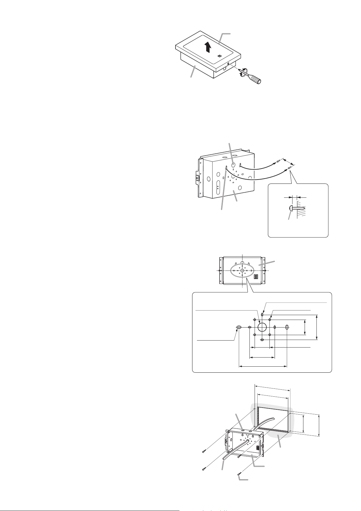
Step 1. Loosen one each of the screws on both
sides of the speaker, then remove the
baffle.
You can remove the baffle by loosening
the screw without taking it out.
Step 2. Install the cabinet on the wall.
The cabinet has knockout holes (ø20.5 mm or ø0.81") for cable routing.
Remove the desired knockout hole depending on the wiring method, and route cables.
2-1. When installing the cabinet on the wall using the hanging holes:
(1) Fix 2 supplied screws (tapping screws 4 x 16)
to the wall leaving about 5 mm (0.2") space
from the wall surface.
(2) Remove the cabinet's knockout, then run the
cables routed from the wall through this hole.
In the case of exposed wiring, fit the supplied
rubber grommet into the knockout hole.
Note: Cut a hole in the grommet's thin
membrane to match the cable size.
(3) Hook the cabinet onto the stick-out screws,
then tighten the screws.
Tip: The shape of cabinet's hanging hole is
so designed to prevent the cabinet from
falling easily even if an outward force is
applied to.
2-2. When installing the cabinet on the wall using other holes:
(1) Remove the cabinet's knockout, then run
the cables routed from the wall through this
hole.
In the case of exposed wiring, fit the supplied
rubber grommet into the knockout hole.
Note: Cut a hole in the grommet's thin
membrane to match the cable size.
(2) Install the cabinet on the wall using the
mounting holes [a], [b] or [c] shown at right.
Note: Since no mounting screws are
supplied with the speaker, separately
prepare them appropriate for the
construction of wall and its thickness.
2-3. When mounting the cabinet into the wall:
(1) Make a mounting hole of 260 x 175 mm
(10.24" x 6.89") in the wall.
(2) Remove the cabinet's knockout hole, run
the cables through this hole, then install
the cabinet using 4 supplied screws
(tapping screw 4 x 16).
Fit the supplied rubber grommet into the
knockout hole.
Note: Cut a hole in the grommet's thin
membrane to match the cable size.
Baffle
Note: To remove, pull in the arrow
direction after loosening screws.
Loosen
Cabinet
Tighten
Knockout hole (ø20.5mm or ø0.81")
About 5 mm (0.2")
Cabinet
Hanging hole
Tapping screw 4 x 16
83.5 mm (3.29")
Wall
(accessory)
Knockout hole: ø20.5 (0.81)
2-5.5 x 10
(0.22 x 0.39) [c]
Knockout hole: ø20.5 (0.81)
Sides: 4 holes
Bottom: 2 holes
Speaker
cable
Cabinet
The figure shows BS-680F.
4-3.5 x 6.5 (0.14 x 0.26) [a]
4-ø4.5 (0.18) [b]
36
(1.42)
60 (2.36)
36 (1.42)
60 (2.36)
115 (4.53)
286 (11.26)
260±3
(10.24±0.12)
wall
Cabinet
Tapping screw 4 x 16 (accessory)
Unit: mm (in)
Unit: mm (in)
150
(5.91)
175±3
(6.89±0.12)
Page 3

Step 3. Perform wiring.
3-1. Connect both the lead-in and lead-out cables to the terminal block attached to the cabinet.
[Applicable cable]
Step 4. Replace the baffle to the cabinet, then tighten 2 screws loosely attached on both sides of the cabinet.
3-2. Insert the fasten terminals fitted at the ends of the HOT, COM, and Earth (BS-680FC only) cables
from the input connector on the cabinet into the taps of the matching transformer on the speaker unit.
Connect the COM cable to the transformer's COM tap, the HOT cable to the desired transformer's
input tap, and the Earth cable (BS-680FC only) to the lug terminal at the transformer base. (Refer to
the figure below.)
The table below shows the relationship between impedance and input power.
Impedance 1.7 kΩ 3.3 kΩ 6.7 kΩ 13 kΩ
100 V line 6 W 3 W 1.5 W 0.8 W
70 V line 3 W 1.5 W 0.8 W 0.4 W
BS-680F Solid wire: ø0.8 – ø1.6 mm (AWG 20 – 14)
7-core twisted wire: 0.75 – 1.25 mm2(AWG 18 – 16)
BS-680FC Solid wire: ø1.0 – ø3.0 mm (AWG 18 – 9)
[Connection of the BS-680F]
To the next speaker
Cabinet
Input connector
From
HOT
the amplifier
COM
[Connection of the BS-680FC]
To the next speaker
Cabinet
From the amplifier
From the amplifier
Input connector
9 mm (0.35”)
To the next speaker
From the amplifier
Thermal fuse
Input connector
HOT (black)
1.7kΩ
3.3kΩ
13kΩ
6.7kΩ
COM
COM (white)
Matching transformer
(on the speaker unit)
13kΩ
1.7kΩ
6.7kΩ
COM
3.3kΩ
Matching transformer
(on the speaker unit)
To the next speaker
HOT
COM
HOT
COM
Input connector
5 mm (0.2”)
Page 4

5. SPECIFICATIONS
Notes
• The design and specifications are subject to change without notice for improvement.
• The Specifications data was measured in an anechoic chamber.
• Reference axis: Axis is on the center of grill surface and perpendicular to the grill surface.
• Reference plane: Plane is on the grill surface and perpendicular to the reference axis.
• Horizontal plane: Plane is containing the reference axis and perpendicular to the reference plane.
• Other technical data: See the specification sheet BS-680F/FC.
BS-680F BS-680FC
6 W (100 V line), 3 W (70 V line)
100 V line:1.7 kΩ (6 W), 3.3 kΩ (3 W), 6.7 kΩ (1.5 W), 13 kΩ (0.8 W)
70 V line: 1.7 kΩ (3 W), 3.3 kΩ (1.5 W), 6.7 kΩ (0.8 W), 13 kΩ (0.4 W)
94 dB at 1 W, 1 m (500 Hz – 5 kHz, pink noise)
77 dB at 1 W, 4 m (100 Hz – 10 kHz, pink noise) according to EN 54-24
89 dB at 1 W, 1 m (100 Hz – 10 kHz, pink noise) converted based on EN 54-24
84 dB at 6 W, 4 m (100 Hz – 10 kHz, pink noise) according to EN 54-24
96 dB at 6 W, 1 m (100 Hz – 10 kHz, pink noise) converted based on EN 54-24
150 Hz – 20 kHz (at 20 dB below peak)
500 Hz: 180° (Horizontal and Vertical); 1 kHz: 140° (Horizontal and Vertical);
2 kHz: 120° (Horizontal), 110° (Vertical); 4 kHz: 100° (Horizontal),
80° (Vertical); according to EN 54-24
16 cm (6") double cone type
Traceability Information for The European Standard EN 54-24: 2008 Loudspeaker for voice alarm systems
Europe for fire detection and fire alarm systems
(EMC directive 2004/108/EC) Certification number: 1438/CPD/0178, Certified year: 10
Environmental type: A (Indoor applications)
In compliance with the British Standard
BS 5839-8: 2008
Solid wire: ø0.8 – ø1.6 mm Solid wire: ø1.0 – ø3.0 mm (AWG 18 – 9)
(AWG 20 – 14)
7-core twisted wire:
0.75– 1.25 mm
2
(AWG 18 – 16)
Push-in connector Screw connector
(Bridging terminal) (Steatite terminal x 2) bridging
Baffle, Cabinet: Steel plate, off white (RAL 9010 or equivalent color), paint
Grille: Surface-treated steel plate net, off white (RAL 9010 or equivalent color), paint
310 (w) x 190 (h) x 87.2 (d) mm (12.2" x 7.48" x 3.43")
2.6 kg (5.73 lb)
Model No.
Rated Input
Rated Impedance
Sensitivity
Maximum
Sound Pressure Level
Frequency Response
Coverage Angle (–6 dB)
Speaker Component
Standard
Applicable Cable
Connection
Finish
Dimensions
Weight
4. WIRING DIAGRAMS
4.1. BS-680F
4.2. BS-680FC
• Accessories
533-06-153-6C
URL: http://www.toa.jp/
Rubber grommet ................................................ 2 Tapping screw (4 x 16) ...................................... 4
Input
connector
HOT
COM
HOT (black)
13 kΩ
6.7 kΩ
3.3 kΩ
1.7 kΩ
COM
COM (white)
Matching
transformer
8 Ω
0
Input
connectors
Earth
HOT
COM
Earth
HOT
COM
13 kΩ
6.7 kΩ
3.3 kΩ
1.7 kΩ
COM
Matching
transformer
8 Ω
Incombustible cablesThermal fuse
(72°C or 161.6°F)
0
1438
 Loading...