

Page 1
SPEAKER SYSTEM
USER MANUAL
BS-301B AS
BS-301W AS
Thank you for using our product.
Traceability Information for Europe (EMC directive 2004/108/EC)
Manufacturer:
TOA Corporation
7-2-1, Minatojima Nakamachi, Chuo-ku, Kobe, Hyago,
Japan
Authorized representative:
TOA Electronics Europe GmbH
Suederstrasse 282, 20537 Hamburg,
Germany
Please follow carefully the instructions stated in the manual to ensure correct installation and to prevent
any damage for the long-lasting use of the speaker unit.
TOA Corporation
URL: http://www.toa.jp/
TOA Corporation
533-06-207-2B
Page 2
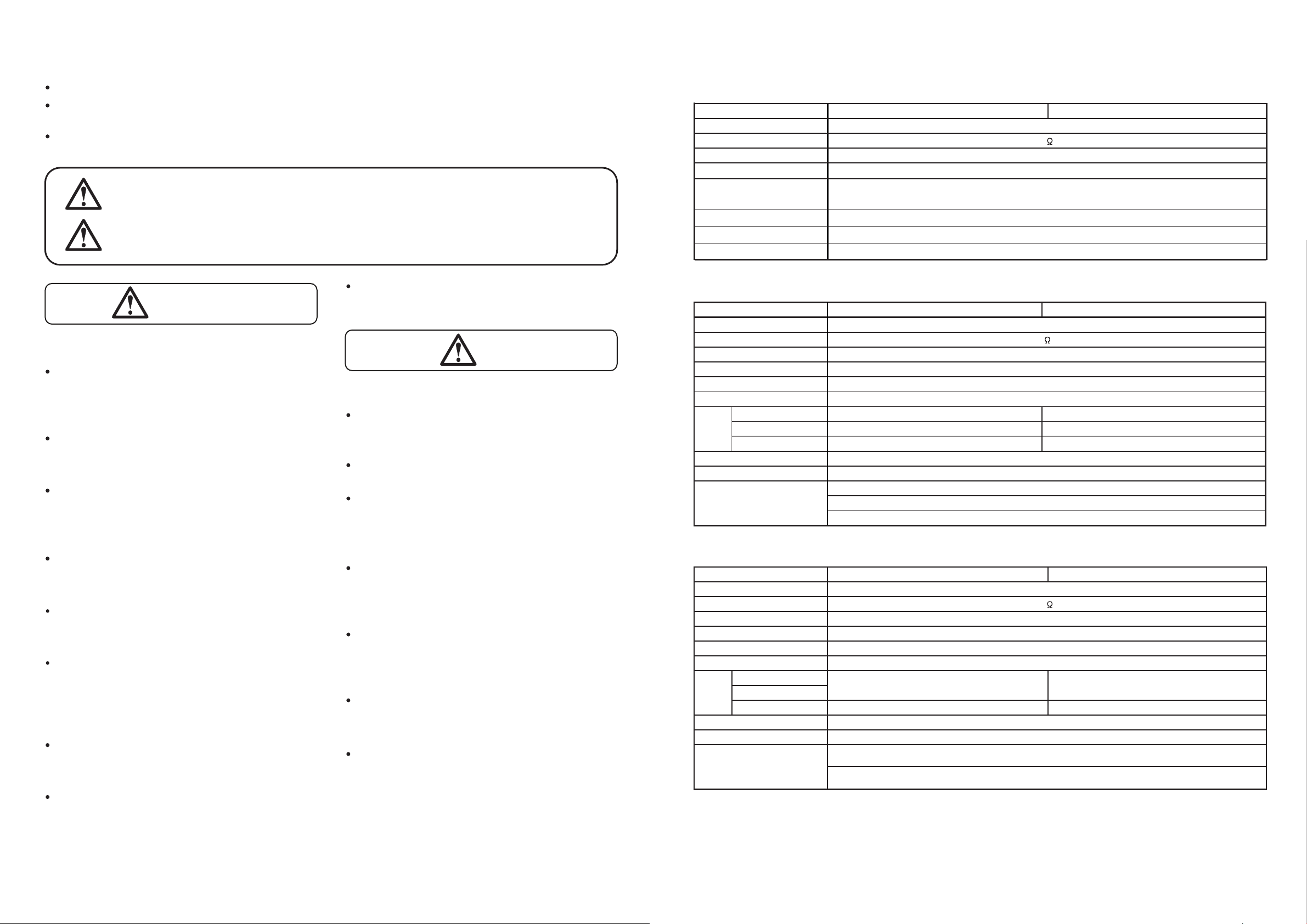
8. SPECIFICATION
8.3. SATELLITE SPEAKER
8.2. SUBWOOFER
The specification may change without notice for improvement
Impedance
Sensitivity
Frequency response
Speaker component
Connection
Speaker box
Front Cover
Speaker bracket Steel plate, black paint Steel plate, white paint
Dimensions
Weight
Speaker Bracket…………………………………...………1
Hexagonal bolts M5 x 12 (with ring and spring ring)…...2
Model
150 ~ 20,000 Hz (-20dB below SPL)
8cm (3") cone-type
Push-in terminals (2 terminal poles)
BS-301B AS BS-301W AS
40W
8
85dB (Pink noise 330 ~ 3,300 Hz / 1W, 1M)
Feature
Accessories
92 (width) x 97.5 (height) x 100 (depth) mm
600g (without bracket)
HIPS Resin (Black) HIPS Resin (White)
Continuous Program Input
Continuous Program Input
Impedance
Sensitivity
Frequency Response
Speaker component
Connection
Speaker cabinet
Particle board with vinyl, black Particle board with vinyl, white
Front Cover
ABS Resin (Black) ABS Resin (White)
Speaker bracket Steel plate, black paint Steel plate, white paint
Dimensions
Weight
Rubber foot…………………………..4
Speaker Mounting Bracket…………4
Taping screws 3 x 14.…….…...……4
Accessories
Feature
210 (width) x 390 (height) x 563 (depth) mm
11,500g (without bracket)
BS-301B AS BS-301W AS
120W per Channel
85dB (1W, 1M) (L or R Channel)
40 ~ 190 Hz (-10dB below SPL) ( L or R Channel)
16cm (6") 2-Speaker
Push-in terminals (8 connected terminal poles)
Model
7
6
1. SAFETY PRECAUTIONS
Read carefully the manual before installing or using the speaker unit
Please understand thoroughly the safety instructions and other important notes pertaining to safety stated in the
manual.
Keep the manual for future reference after you have finished reading.
Installation of speaker unit on bracket
During Installation of Speaker Unit
Indicates a potentially hazardous situation which, if mishandled, could
result in death or serious personal injury.
Indicates a potentially hazardous situation which, if mishandled, could
result in moderate or minor personal injury, and/or property damage.
WARNING
CAUTION
2
※
WARNING
CAUTION
Install the unit on a location which is secure enough
to support the speaker unit and mounting brackets.
Failure to do so may cause the speaker unit to fall
and inflict injury to people / damage the equipment.
Do not apply other methods to mount the bracket
other than the method stated in the manual. Speaker
unit may fall and cause injury to people.
Use the proper screws in accordance with the composition and structure of the ceiling or wall. Failure to
do so may cause the speaker to fall and inflict injury
to people.
Tighten the screws properly. Ensure the bolt is tightened securely after the speaker unit is installed to
prevent it from falling and inflicting injury to people.
Do not install on an unstable location which may
cause the speaker unit to fall due to the strong or
continuous vibration.
The speaker is designed for indoor use, do not install
outdoors. Failure to do so may cause damage on the
speaker unit and or cause it to fall which may inflict
injury to people. Speaker is also prone to rain which
may cause short-circuit.
Do not install the speaker in a room without proper
ventilation. Bracket will get rusty easily which may
cause the speaker to fall and inflict injury to people.
Do not use anti-corrosion liquid. Anti-corrosion on
plastic (resin) or rubber may cause damage on the
speaker unit. The speaker unit may fall and inflict
injury on people
Be
When unpacking or storage the unit, be sure to handle
it with two or more persons. Falling or dropping the
unit may cause personal injury.
Owning to the subwoofer's size weight, be sure that
at least two persons are available to install it. Failure
to do so could result in personal injury.
careful of the sharp edges of the unit which may
cause injury.
To prevent short-circuit, ensure the amplifier is
always in the OFF condition when connecting it to
the speaker unit.
When Speaker Unit is in use
Do not place any heavy item on the speaker
because it may cause the speaker to fall which may
cause injury to people or damage on the equipment.
The heavy item may also fall and endanger safety.
Do not operate the speaker for long duration of time
with distorted sound. This indicates false operation
and it may introduce heat which subsequently may
cause fire.
Do not sit, stand on or dangle from the speaker unit
because it may cause the speaker to fall and inflict
injury to people as well as damage the equipment.
Do regular check of the equipment for early detection of any damage on the speaker unit or corrosion
on the mounting bracket. Failure to do so may cause
the speaker unit to fall and inflict injury to people.
8.1. SPEAKER SYSTEM
Model
Total input power
Rated Impedance
Sensitivity / SPL
Frequency response
Speaker feature
Mounting
Input Connector
Total Weight
BS-301B AS BS-301W AS
83dB (Pink noise 330 ~ 3,300 Hz, 1W, 1M) L ch or R ch. only + 2 satellite
240W (2-Way)
6
40 ~ 20,000 Hz (L or R ch. Subwoofer + 2 satellite)
Subwoofer .......................1pc (Look at point 8.2)
Satellite speaker ..............4pc (Look at point 8.3)
Floorstanding / on-wall / on ceiling
Push-in terminals
13.9 kg (without bracket)
Page 3

6.2.1. Installation on Floor
6.2.2. Installation on Wall
6.2.3. Installation on Ceiling
Use the rubber foot to install the subwoofer on the floor. Ensure the floor is even and flat so the subwoofer will
not move. Install the rubber foot on the side facing the floor.
For wall installation, unscrew two screws on the subwoofer. Take note of distance between the two screw holes
to be mounted on the wall (see image 4.3.2.)
For ceiling installation, please unscrew all screws (4 pieces) on the subwoofer. Take note of the distance
between the two screw holes to be mounted on the ceiling (see image 4.3.2.)
4-Rubber foot
Rubber foot
Floor
Wall angle
Vertical position Horizontal position
4-Taping screws 3x14
Mount the bracket
on the wall
Unscrew 4 screws from
Subwoofer
Place the screws back
onto Subwoofer
Ceiling
Ceiling
Unscrew 2 screws
from subwoofer
Place the screws back
onto Subwoofer
40 50
50
50
50
50
40 50
2. GENERAL DESCRIPTION
The speaker system model BS-301 series is a speaker high-power with 2-way system that suitable for indoor
use only.
The wide range of frequency as well as capability of generating high sound pressure level make it an efficient
speaker to be used in a spacious room.
It is consisted of a subwoofer and four pieces satellite speakers.
he provided brackets allow the speaker to be mounted on various locations and direction radiations.T
The mounting brackets come together with the product as accessories.
3. DESCRIPTION ON OVERLOAD PROTECTION
The speaker unit is equipped with an overload protector. The system shall protect the speaker unit from overload
input which exceeds the allowed capacity.
Speaker’s volume will turn lower if the input to the speaker exceeds the maximum capacity of the speaker.
In such event, please turn down the amplifier volume to the minimum level and wait for 10 seconds. The system
shall automatically reset to normal condition. You may then gradually re-adjust the amplifier volume to the level
lower then the previous volume.
Note:
Screws to mount the
bracket are not available
Note:
Screws to mount the bracket
on ceiling are not available
7. THE SPEAKER CABEL CONNECTIONS
Important Note!
The system does not entirely protect against overload. Prolonged overload input to the speaker unit will cause
the system to malfunction. As such, the overload input will flow in and damage the speaker unit.
It is important to prevent prolonged overload input exceeding the maximum limit from flowing into the speaker
unit.
4. DIMENSIONAL DIAGRAM
4.1. SATELLITE SPEAKER
°
(Turn)
5
.
2
2
[Top] [ Bottom]
4.2. SUBWOOFER
Fixing seal
Note:
Screw hole is enclosed by the
fixing seal from the factory.
Be fo re mo un ting the b racket,
fix i ng s eal sha l l b e re m oved
first.
Plea s e us e a s m all f lathe a d
screwdriver.
Find a big gap to open fixing seal.
Don't entering screwdriver too depth
(use its point)
210 563
390
[Front] [Side]
6
Speaker unit
Subwoofer unit
To Amplifier
OUTPUT
LEFTRIGHT
INPUT
RIGHT LEFT
[Rear]
Speaker unit
Input Terminal Speaker
Input Terminal
Speaker unit
92
100
To Speaker
9mm
To Subwoofer
97.5
(Peeled cable)
To Amplifier
[Front] [Side]
1°
[Rear]
2-M5 Screw holes (top and bottom)
(Screw length max. 12mm or 0.47inch)
Input Terminal
Input/Output
Terminal
[Rear]
Size : mm
3
Page 4

4.3. BRACKET (TO MOUNT SPEAKER)
4.3.1. BRACKET FOR SATELLITE SPEAKER 4.3.2. BRACKET FOR SUBWOOFER
5. SPEAKER CABLE CONNECTIONS
5.1. SATELLITE SPEAKER
5.2. SUBWOOFER
6. INSTALLATION
6.1. SATELLITE SPEAKER
[Rear] [Rear]
9mm
[0.35inch]
9mm
[0.35inch]
(Length of peeled cable) (Length of peeled cable)
42
68
[Bottom]
[Top]
[Side]
Bracket-B
Bracket-A
Tightening Screw
55
155
222
[Side]
45
45
30 360
30
16-Ø9
387
30
360
30
45
8-Ø9
[Distance of the screw
holes on wall]
[Distance of the screw
holes on ceiling]
[Distance of the screw
holes on wall or ceiling]
32
3-Ø4.5
20
4
6.1.2.1 Installation on Wall
[single-system installation sample]
[double-system installation sample]
6.1.2.2 Installation on Ceiling
6.2. SUBWOOFER
Speaker unit
Speaker unit
5
0o
(Horizontal)
90
o
90
o
(Turn to left)
90
o
(Turn to right)
(Top View)
(Side View)
0
o
(Vertical)
0
o
(Vertical)
M5x12 Screw
M5x12 Screw
M5x12 Screw
Speaker unit
Bracket
Bracket
Bracket
Note:
Red : + (positive)
Black : - (negative)
Mount bracket
to the wall
Mount bracket
to the wall
Mount bracket to
the ceiling
Mount bracket to
the ceiling
Ceiling
Ceiling
Note:
Screws to mount
the bracket onto the
wall are not provided
Note:
Screws to mount the bracket
onto the ceiling are not provided
Loosen the tightening screw (right and left) to install
the bracket to the speaker unit. Take note of
Bracket-A; this is the part of the bracket which will be
attached to the wall or ceiling when installing the
speaker unit.
Place the speaker unit on an even and flat surface.
If the speaker unit is placed on glass or slippery surface, you may want to cover the surface with a cloth to prevent
the speaker from moving.
Before installing the bracket to speaker unit, remove / open the fixing seal enclosing the screw holes. Use a small
flathead screwdriver. Place the flathead screwdriver into the fixing seal slot (see image 4.1.). For installation of
single system, please remove only one fixing seal and for double system, please remove two fixing seals (top and
below) on one of the speaker units.
6.1.1. Speaker Unit installation without bracket
6.1.2. Speaker Unit installation with bracket
[Front]
[single-system installation sample] [double-system installation sample]
M5x12 Screw
M5x12 Screw
Size : mm
The sound generated by the subwoofer may differ, depending upon the mounting position. The Subwoofer installation samples illustrated here are some of the appropriate positions for room installation. It is recommended to
place the subwoofer at the corner of the room for better sound (especially bass).
 Loading...