

Page 1
OPERATING INSTRUCTIONS
SPEAKER SYSTEMS BS-301B
BS-301W
1. SAFETY PRECAUTIONS ........................... 2
2. GENERAL DESCRIPTION ......................... 3
3. DESCRIPTION ON
OVERLOAD PROTECTION ....................... 3
4. DIMENSIONAL DIAGRAMS ....................... 3
5. INSTALLATION .......................................... 4
6. CONNECTION ............................................ 7
7. AMPLIFIER OPERATIONS ........................ 7
8. SPECIFICATIONS ...................................... 8
Thank you for purchasing TOA's Speaker System.
Please carefully follow the instructions in this manual to ensure long, trouble-free use of your equipment.
TABLE OF CONTENTS
533-06-237-7A
Page 2
2
CAUTION
When Installing the Unit
• Install the unit only in a location that can
structurally support the weight of the unit and the
mounting bracket. Doing otherwise may result in
the unit falling down and causing personal injury
and/or property damage.
• Since the unit is designed for in-door use, do not
install it outdoors. If installed outdoors, the aging of
parts causes the unit to fall off, resulting in personal
injury. Also, when it gets wet with rain, there is a
danger of electric shock.
• Owing to the unit's size and weight, be sure that at
least two persons are available to install the unit.
Failure to do so could result in personal injury.
• Do not use other methods than specified to mount
the bracket. Extreme force is applied to the unit
and the unit could fall off, possibly resulting in
personal injuries.
• Use nuts and bolts that are appropriate for the
ceiling's or wall's structure and composition. Failure
to do so may cause the speaker to fall, resulting in
material damage and possible personal injury.
• Tighten each nut and bolt securely. Ensure that the
bracket has no loose joints after installation to
prevent accidents that could result in personal
injury.
• Do not mount the unit in locations exposed to
constant vibration. The mounting bracket can be
damaged by excessive vibration, potentially
causing the unit to fall, which could result in
personal injury.
• Do not use anti-rust lubricant. If it contacts resin or
rubber parts, they could deteriorate and cause the
unit to fall, possibly resulting in personal injury.
When Installing the Unit
• Avoid installing the unit in humid or dusty locations,
in locations exposed to the direct sunlight, near the
heaters, or in locations generating sooty smoke or
steam as doing otherwise may result in fire or
electric shock.
• When unpacking or moving the unit, be sure to
handle it with two or more persons. Falling or
dropping the unit may cause personal injury and/or
property damage.
• Avoid placing the unit in a doorway or other high
traffic area as people may trip on the equipment
and cords, or be injured by falling objects.
• Avoid touching the unit's sharp metal edge to
prevent injury.
• To avoid electric shocks, be sure to switch off the
amplifire's power when connecting speakers.
When the Unit is in Use
• Do not place heavy objects on the unit as this may
cause it to fall or break which may result in
personal injury and/or property damage. In
addition, the object itself may fall off and cause
injury and/or damage.
• Do not operate the unit for an extended period of
time with the sound distorting. Doing so may cause
the connected speakers to heat, resulting in a fire.
• Do not stand or sit on, nor hang down from the unit
as this may cause it to fall down or drop, resulting
in personal injury and/or property damage.
• Have the unit checked periodically by the shop
from where it was purchased. Failure to do so may
result in corrosion or damage to the unit or its
mounting bracket that could cause the unit to fall,
possibly causing personal injury.
1. SAFETY PRECAUTIONS
• Before installation or use, be sure to carefully read all the instructions in this section for correct and safe
operation.
• Be sure to follow all the precautionary instructions in this section, which contain important warnings and/or
cautions regarding safety.
• After reading, keep this manual handy for future reference.
WARNING
Indicates a potentially hazardous situation which, if mishandled, could
result in death or serious personal injury.
Indicates a potentially hazardous situation which, if mishandled, could
result in moderate or minor personal injury, and/or property damage.
WARNING
CAUTION
Page 3
3
2. GENERAL DESCRIPTION
Designed for indoor use, the BS-301 series is a 2-way speaker system featuring high power handling.
Consisting of 4 satellite speakers and a subwoofer, this speaker system delivers a high sound pressure level
over a wide frequency range of sound. It is ideal for installation in small shops and BGM applications.
The supplied mounting bracket permits the speaker system to be installed at various sites and various
direction angles.
3. DESCRIPTION ON OVERLOAD PROTECTION
The speaker unit is equipped with an overload protection circuitry. This circuitry will protect the speaker unit
from overload input which exceeds the allowed capacity.
Speaker's volume will turn lower if the input to the speaker exceeds the maximum capacity of the speaker.
In such event, please turn down the amplifier volume to the minimum level and wait for about 10 seconds. The
circuitry will automatically revert to normal condition. Then, set the volume at a lower level than before.
Note
The overload protection circuitry does not completely protect the speaker unit against overload. Prolonged
overload input to the speaker unit will cause the system to malfunction. As such, the overload input will flow in
and damage the speaker unit.
It is important to prevent prolonged overload input exceeding the maximum limit from flowing into the speaker
unit.
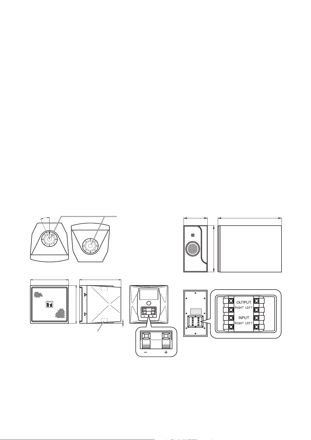
4. DIMENSIONAL DIAGRAMS
4.1. Satellite Speaker 4.2. Subwoofer
Unit: mm (in)
[Top] [Bottom]
[Front] [Side] [Rear]
(Rotation angle)
22.5°
92 (3.62) 100 (3.94)
97.5 (3.84)
Bracket mounting positions
Note
When the mounting bracket
is not attached, affix the
supplied sticker for satellite
speaker.
1°
[Front] [Side]
210 (8.27)
390 (15.35)
[Rear]
Input/output terminals
563 (22.17)
Screw holes (M5, top and bottom,
thread length: max. 12 mm or 0.47")
Input terminals
Note for terminal polarities
Red: + (HOT)
Black: – (COM)
Page 4

4
5. INSTALLATION
5.1. Satellite Speaker
Notes
• When mounting the satellite speaker mounting
bracket to a wall or ceiling, secure the Bracket A at 3
points to the wall or ceiling.
Use the Bracket B only to support the speaker.
• Screws for mounting the bracket to the wall or ceiling
are not supplied. Use screws that are appropriate for
the ceiling's or wall's structure and composition.
4.3. Mounting Brackets
4.3.1. Satellite speaker mounting bracket 4.3.2. Subwoofer mounting bracket
Loosen the tightening screws (right and left) to install
the bracket to the speaker unit.
Unit: mm (in)
5.1.1. Speaker direction angle
[Top]
[Side]
[Bottom]
68 (2.68)
Bracket B (for speaker)
Tightening screw
Bracket A (for wall/
ceiling/speaker)
42 (1.65)
[Wall/Ceiling mounting
dimension]
32
(1.26)
3-φ4.5 (0.18)
20 (0.79)
222 (8.74) 55
155 (6.1)
[Wall mounting dimension]
16-φ9 (0.35)
30
(1.18) (1.18)(12.99)
330 30
[Front][Side]
(2.17)
45
432
45
(1.77) (17.01)(1.77)
Satellite speaker (side view) Satellite speaker (top view)
0°
(Horizontal)
90°
Bracket A
Bracket B
Satellite speaker mounting
bracket (accessory)
Note
Loosen 2 tightening screws
to open or close the bracket.
90°
(Toward the left)
(Vertical)
90°
0°
(Vertical)
(Toward the right)
0°
Page 5

5
5.1.2. Wall mounting
[Single speaker installation] [Double-stack installation]
Note
The satellite speaker can be secured more firmly if another
satellite speaker mounting bracket is added to the wall on the
side of upper satellite speaker’s top panel.
5.1.3. Ceiling mounting
[Single speaker installation] [Double-stack installation]
Sticker for satellite
speaker (accessory)
Satellite speaker
Satellite speaker
Satellite speaker
mounting screws
M5 x 12 (accessory)
Satellite speaker mounting
bracket (accessory)
Satellite speaker mounting screw
M5 x 12 (accessory)
Satellite speaker
mounting screw
M5 x 12 (accessory)
Sticker for satellite
speaker (accessory)
Satellite speaker
mounting brackets
(accessory)
Satellite speaker mounting
bracket (accessory)
Ceiling
Satellite speaker
Ceiling
Satellite speaker
mounting screw
M5 x 12 (accessory)
Satellite speakers
Ceiling
Affix the supplied sticker for
satellite speaker to the
mounting bracket position when
the bracket is not mounted.
Satellite speaker mounting
bracket (accessory)
Sticker for satellite
speaker (accessory)
Ceiling
Satellite speaker mounting
screws M5 x 12 (accessory)
Page 6

6
5.2. Subwoofer
The sound generated by the subwoofer may differ depending on the installation position. It is recommended to
place the subwoofer at the corner of the room for better sound (especially bass).
5.2.1. Installation on floor
Use the rubber feet to install the subwoofer on the floor. Ensure that the floor is even and flat so the
subwoofer will not move. Install the rubber feet on the side facing the floor.
Unit: mm (in)
5.2.2. Wall mounting
Screws for mounting the bracket
to the wall are not supplied.
Use screws that are appropriate
for the wall's structure and
composition.
Failure to do so may cause the
speaker to fall, resulting in
material damage and possible
personal injury.
WARNING
[Vertical position] [Horizontal position]
Wall
Rubber feet (4 pieces)
(accessory)
Tapping screws 3 x 14 (4 pieces)
(accessory)
Floor
[Rubber feet mounting dimension]
• When installing the unit vertically • When installing the unit horizontally
50 (1.97)
40 (1.57)
40 (1.57)
50 (1.97)
Rubber foot
50 (1.97)
50 (1.97)
50 (1.97)
Subwoofermountingbracket
Subwoofer
Wall
Floor
Rubber foot
50 (1.97)
Step 1. Remove 4 screws on the
Subwoofermountingscrews
M8x50(accessory)
Step 4.
Mount 2 subwoofer
Step 2.
mounting brackets
to the wall.
Note: The removed screws are not used.
Secure the subwoofer to
the mounting brackets using
the 2 supplied screws.
subwoofer's side panel.
Subwoofermountingscrews
M8x50(accessory)
Step 5.
Mount 2 subwoofer
mounting brackets to
the speaker's upper
side as well.
Step 3.
Place the subwoofer onto
the mounting brackets.
Page 7

7
6. CONNECTION
For connections among the amplifier's output terminals,
the subwoofer's input/output terminals, and the satellite
speaker's input terminals, connect negative (–) to
negative (–) and positive (+) to positive (+).
7. AMPLIFIER OPERATIONS
7.1. Stereo Amplifier Operation [2 inputs – 2 outputs] (Recommended)
[Wiring diagram]
7.2. Monaural Amplifier Operation [1 input – 2 outputs]
[Wiring diagram]
Note
When operating the speaker as in the diagram above (amplifier output of 1 channel), the rated impedance is 8 Ω.
Satellite speaker
OUTPUT
LEFTRIGHT
INPUT
RIGHT LEFT
Input terminals
Input terminal
Satellite
+
speaker
Subwoofer (rear)
To satellite speaker
To subwoofer
To amplifierTo amplifier
Note
Eachcoloredterminalof
thesubwooferandsatellite
speakerindicatesthe
followingpolarities.
Redterminal:+(HOT)
Blackterminal:‒(COM)
[Cable end treatment]
Satellite
Speaker (1)
Input terminals
OUTPUT 1 ch (–)
Satellite
Speaker (2)
(–) (+)(–) (+)(–)(+)(–)
Amplifier
OUTPUT 1 ch (+)
OUTPUT 1 ch (–)
OUTPUT 2 ch (+)
OUTPUT 2 ch (–)
(+)
Amplifier
OUTPUT 1 ch (+)
Amplifier
Subwoofer input/output terminals
(+)
(–)
(–)
(+)
INPUT R (+)
INPUT R (–)
INPUT L (+)
INPUT L (–)
Amplifier
OUTPUT 2 ch (+)
Subwoofer
(+)
(–)
(–)
(+)
OUTPUT 2 ch (–)
OUTPUT R (+)
OUTPUT R (–)
OUTPUT L (+)
OUTPUT L (–)
Amplifier
Satellite
Speaker (3)
9 mm
(0.35")
Satellite
Speaker (4)
Input terminals
Satellite Speakers
(+)
Speaker (1)
(–)
(+)
Speaker (2)
(–)
(+)
Speaker (3)
(–)
(+)
Speaker (4)
(–)
Satellite
Speaker (1)
Input terminals
Satellite
Speaker (2)
(–) (+)(+)(–) (–)(+)(–)
(+)
OUTPUT 1 ch (+)
Amplifier
OUTPUT 1 ch (+)
OUTPUT 1 ch (–)
Subwoofer input/output terminals
(+)
(–)
(–)
(+)
Amplifier
INPUT R (+)
INPUT R (–)
INPUT L (+)
INPUT L (–)
Subwoofer
OUTPUT R (+)
OUTPUT R (–)
OUTPUT L (+)
OUTPUT L (–)
(+)
(–)
(–)
(+)
Amplifier
OUTPUT 1 ch (–)
Satellite
Speaker (3)
Satellite
Speaker (4)
Input terminals
Satellite Speakers
(+)
Speaker (1)
(–)
(+)
Speaker (2)
(–)
(+)
Speaker (3)
(–)
(+)
Speaker (4)
(–)
Page 8

BS-301B BS-301W
Continuous program: 160 W* x 2 channels
Continuous pink noise: 80 W* x 2 channels
4 Ω* x 2 channels
81 dB (1 W, 1 m)* x 2 channels
40 Hz – 20 kHz* x 2 channels
13.9 kg or 30.64 lb (excluding the supplied brackets)
6 Ω x 2 channels
16 cm (6.5") cone type x 2 channels
Front panel: ABS resin, black Front panel: ABS resin, white
Enclosure: Wood Enclosure: Wood
Speaker bracket: Steel plate, black, Speaker bracket: Steel plate, white,
paint paint
210 (w) x 390 (h) x 563 (d) or 8.27" x 15.35" x 22.17"
11.5 kg or 25.35 lb (excluding the supplied brackets)
8 Ω
8 cm (3") cone type
Enclosure, front panel: Enclosure, front panel:
HIPS resin, black HIPS resin, white
Speaker bracket: Speaker bracket:
Steel plate, black, paint Steel plate, white, paint
92 (w) x 97.5 (h) x100 (d) mm (3.62" x 3.84" x 3.94")
600 g or 1.32 lb (excluding the supplied brackets)
Subwoofer ... 1, Satellite speaker ... 4
Subwoofer mounting Subwoofer mounting
bracket (black) ............................ 4 bracket (white) ..............................4
Rubber foot .................................... 4 Rubber foot .................................... 4
Tapping screw 3 x 4 ...................... 4 Tapping screw 3 x 4 ...................... 4
Subwoofer mounting Subwoofer mounting
screw M8 x 50 ............................ 4 screw M8 x 50 .......................... 4
Satellite speaker mounting Satellite speaker mounting
bracket (black) ............................ 6 bracket (white) ............................ 6
Satellite speaker mounting Satellite speaker mounting
screw M5 x 12 ............................ 8 screw M5 x 12 ............................ 8
Sticker for satellite Sticker for satellite
speaker (black) .............................. 8 speaker (white) ............................ 8
Model No.
Power Handling Capacity
Rated Impedance
Sensitivity
Frequency Response
Total Weight
Subwoofer
Rated Impedance
Speaker Component
Finish
Dimensions
Weight
Satellite Speaker
Rated Impedance
Speaker Component
Finish
Dimensions
Weight
Components
Accessories
URL: http://www.toa.jp/
Traceability Information for Europe
Manufacturer:
TOA Corporation
7-2-1, Minatojima-Nakamachi, Chuo-ku, Kobe, Hyogo,
Japan
Authorized representative:
TOA Electronics Europe GmbH
Suederstrasse 282, 20537 Hamburg,
Germany
8. SPECIFICATIONS
* Overall characteristics measured in a set configuration of a subwoofer (L or R channel) and 2 satellite
speakers.
Note: The design and specifications are subject to change without notice for improvement.
 Loading...