

Page 1
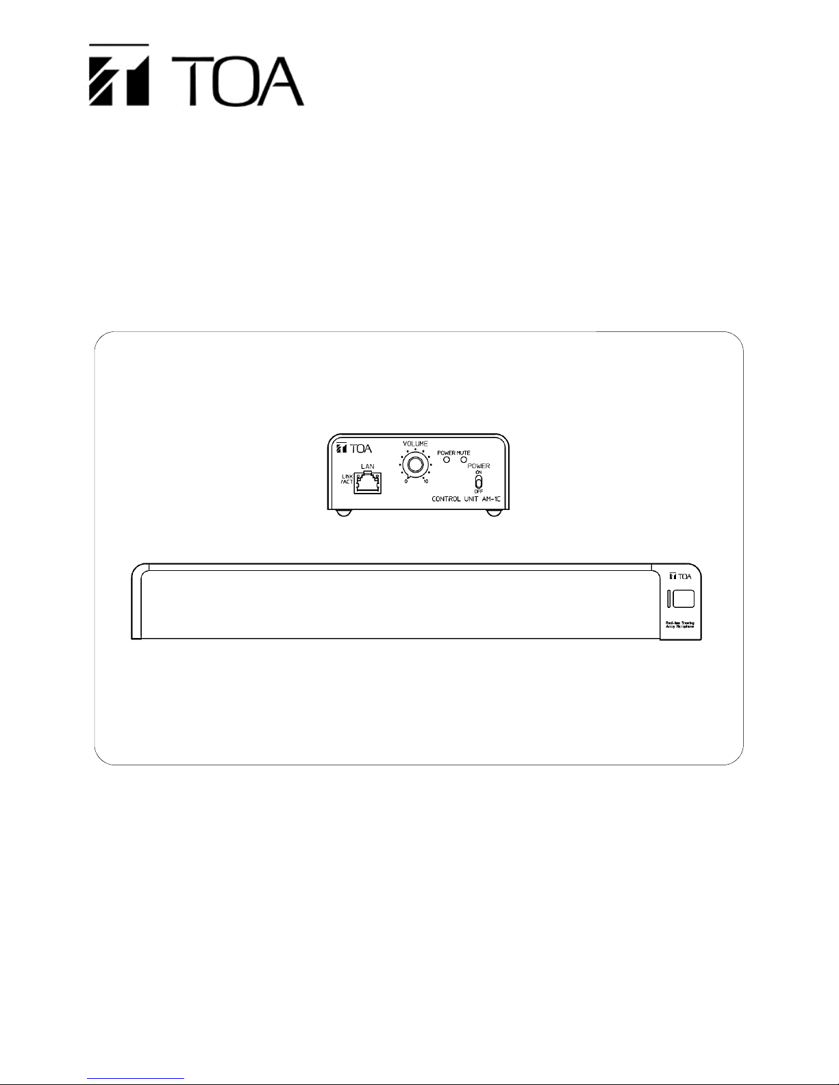
AM
-1
QUICK SETUP GUIDE
AM-1 Setup Guide for the
Polycom® Video Conferencing Systems
*POLYCOM
of Polycom, Inc., and are registered and/or common law marks in the United States and various other countries.
®
and the names and marks associated with Polycom's products are trademarks and/or service marks
Page 2

TABLE OF CONTENTS
1. ABOUT THIS SETUP GUIDE ............................................................ 3
3. SETUP WITH “Group 500” ............................................................... 4
4. SETUP WITH “Group 700” ............................................................... 5
5. SETUP WITH “HDX 7000” ................................................................ 6
6. SETUP WITH “HDX 8000” ................................................................ 7
7. SETUP WITH “HDX 9000 Series” .................................................... 8
8. SPECIFICATIONS OF AM-1 ........................................................... 10
2
Page 3

1. ABOUT THIS SETUP GUIDE
This setup guide shows how to use TOA’s AM-1 Real-time Steering Array Microphone System with the
Polycom® Video Conferencing Systems for better performance. The applicable models from Polycom®
are;
Polycom® RealPresence® Group Series (Group 500/700)
Polycom® HDX® Systems (HDX 9006/9004/9002/9001/7000)
*Group 300/550 and HDX 4000/6000 are not recommended to use with the AM-1, because the echo
canceling feature is not available for external microphone input.
For more detailed settings for AM-1, please refer AM-1’s Operating Instructions.
2. GENERAL INFORMATION OF AM-1
The AM-1 Real-time Steering Array Microphone System is a sophisticated microphone system, capable
of detecting a sound source location, and steering the microphone’s beam angle automatically in realtime to capture the targeted sound more efficiently. In addition, the unique user-friendly app allows the
user to monitor the status of the sound source, and make changes to its detailed setting parameters by
using an iPad™.
Key Features
The microphone unit is equipped with 8 microphone elements able to achieve the line array effect
with a narrow horizontal dispersion angle of 50 degrees.
The unit is able to detect a sound source location and steer the microphone’s beam angle
automatically in real-time to focus on the targeted sound source.
The dedicated user-friendly GUI is available for use with an iPad™, which allows monitoring of
the sound source tracking status and setting of detail parameters. It is also possible to change
parameter settings via a browser, when using a PC.
The unit has a simple mute function with a physical mute switch on the microphone unit or
through the GUI. The mute switch function of the microphone unit can be disabled through a GUI
setting.
It is equipped with two outputs: adjustable analog audio output level, and AES/EBU digital audio
output.
3
Page 4
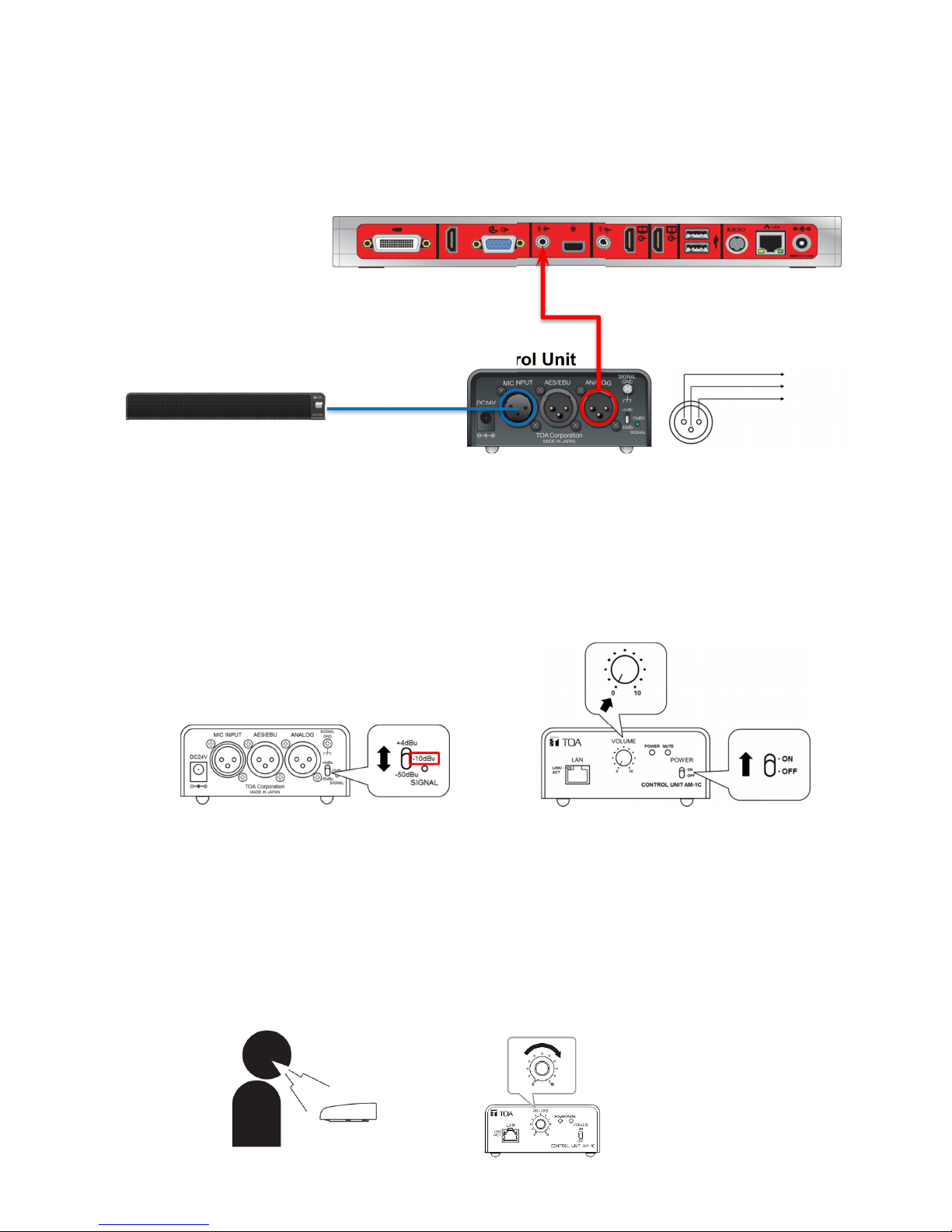
3. SETUP WITH “Group 500”
Audio Input1 (3.5mm)
CONNECTIONS
AM-1 Microphone Unit
SETTINGS
Step1.
Step2.
Step3.
Step4.
Step5.
Step6.
Step7.
Confirm all devices are connected properly as shown above.
Make sure that the audio output level of the AM-1 Control Unit is set to “-10dBv” and the volume
control is set to “0”.
In the web interface of Group 500, go to
Enable
Enable
Adjust the
Use 3.5 mm Input for Microphone
Echo Canceller
3.5 mm Level
While speaking to the microphone from an appropriate distance, adjust the output level with the
volume control. The
Audio Meter
Group 500
.
if necessary.
on Group 500 should peak at about 5 dB for normal speech.
*When the Audio Input 1 is used for external equipment (Use 3.5
mm Input for Microphone enabled), the audio is mixed with the
input on the Polycom microphone array input and sent to the far
end. This input will be muted when the local mute is activated.
XLR(3P-Female) to 3.5mm Cable
Control Unit
1: Ground
2: Hot
3: Cold
Admin Settings > Audio/Video > Audio >Audio Input.
.
4
Page 5
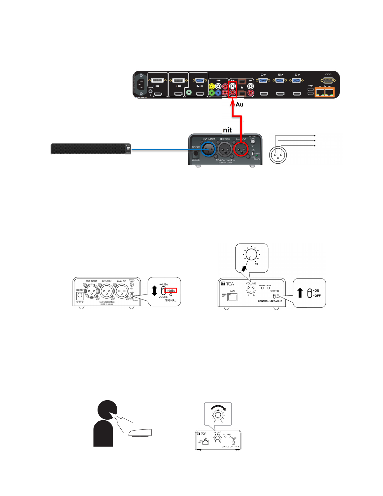
4. SETUP WITH “Group 700”
G
roup
700
AM-1 Microphone Unit
Control Unit
Audio Input1 (RCA
Stereo
)
CONNECTIONS
SETTINGS
Step1.
Step2.
Step3.
Step4.
Step5.
Step6.
Step7.
Confirm all devices are connected properly as shown above.
Make sure that the audio output level of the AM-1 Control Unit is set to “-10dBv” and the volume
control is set to “0”.
In the web interface of Group 700, go to
Select Input Type
Enable
Adjust the
Echo Canceller
Audio Input Level
Line
.
.
if necessary.
While speaking to the microphone from an appropriate distance, adjust the output level with the
volume control. The
Audio Meter
on Group 700 should peak at about 5 dB for normal speech.
XLR(3P-Female) to RCA Cable
1: Ground
2: Hot
3: Cold
Admin Settings > Audio/Video > Audio >Audio Input.
5
Page 6
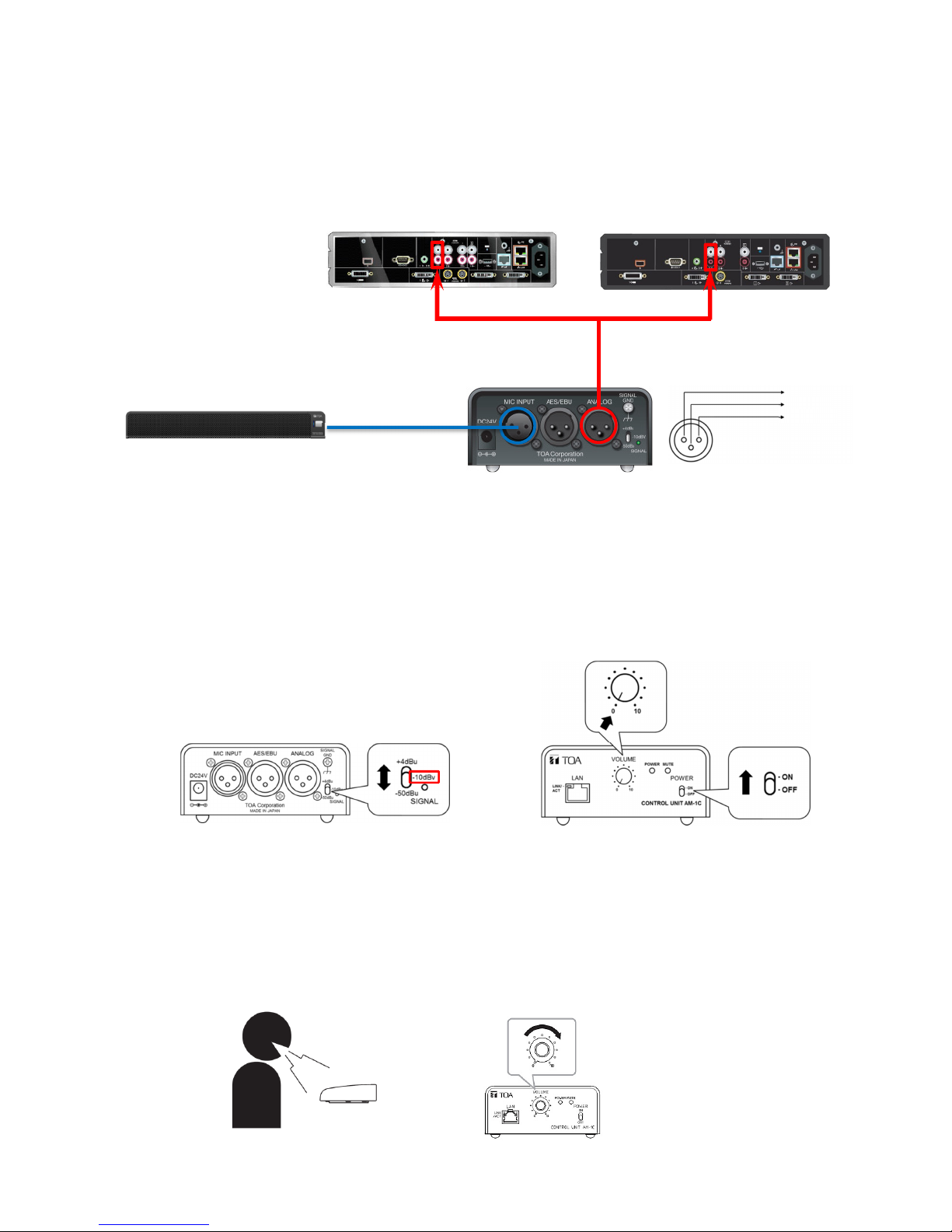
5. SETUP WITH “HDX 7000”
AM-1 Microphone Unit
Control Unit
Audio Input1 (3.5mm)
(Hardware Versions
D)
HDX 7000
CONNECTIONS
SETTINGS
Step1.
Step2.
Step3.
Step4.
Step5.
Step6.
Confirm all devices are connected properly as shown above.
Make sure that the audio output level of the AM-1 Control Unit is set to “-10dBv” and the volume
control is set to “0”.
In the local interface of HDX 7000, go to
Enable
Echo Canceller
Adjust the volume level for
While speaking to the microphone from an appropriate distance, adjust the output level with the
volume control.
*Audio Input 1 is not associated with any particular video
input, and it is not included in audio mix of output 1.
(Hardware Versions A, B, C)
Admin Settings > Audio.
.
audio input 1
if necessary.
XLR(3P-Female) to RCA Cable
1: Ground
2: Hot
3: Cold
6
Page 7
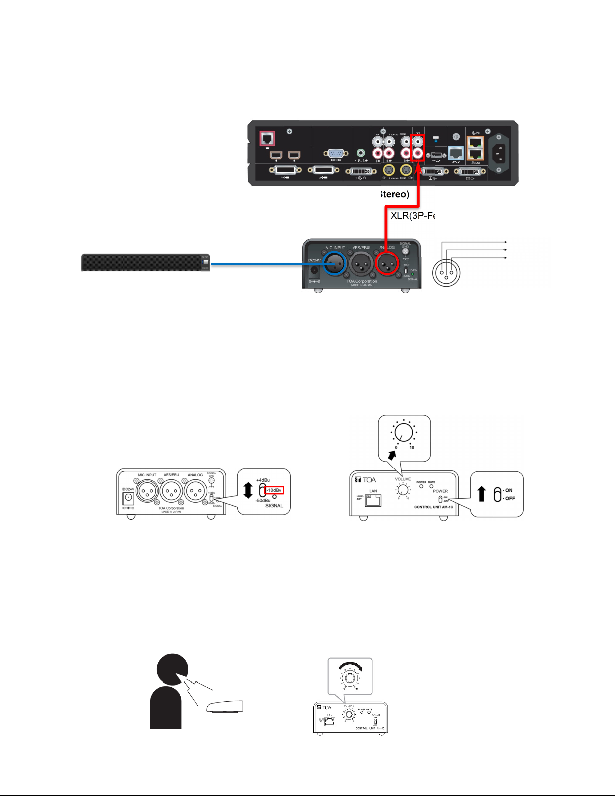
6. SETUP WITH “HDX 8000”
HDX 8000
Audio Input1 (RCA Stereo
)
CONNECTIONS
AM-1 Microphone Unit
SETTINGS
*Audio Input 1 is not associated with any particular video
input, and it is not included in audio mix of output 1.
XLR(3P-Female) to RCA Cable
Control Unit
1: Ground
2: Hot
3: Cold
Step1.
Step2.
Step3.
Step4.
Step5.
Step6.
Confirm all devices are connected properly as shown above.
Make sure that the audio output level of the AM-1 Control Unit is set to “-10dBv” and the volume
control is set to “0”.
In the local interface of HDX 8000, go to
Enable
Adjust the volume level for
While speaking to the microphone from an appropriate distance, adjust the output level with the
volume control.
Echo Canceller
.
audio input 1
Admin Settings > Audio.
if necessary.
7
Page 8
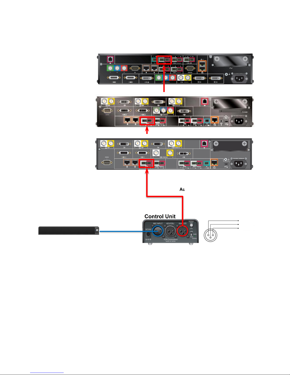
7. SETUP WITH “HDX 9000 Series”
HDX 9006
AM-1 Microphone Unit
Control Unit
Audio Input1 (
Phoenix
)
HDX 9002
CONNECTIONS
HDX 9004
*Audio Input 1 is not associated with any particular video
input, and it is not included in audio mix of output 1.
XLR(3P-Female) to Phoenix
1: Ground
2: Hot
3: Cold
8
Page 9
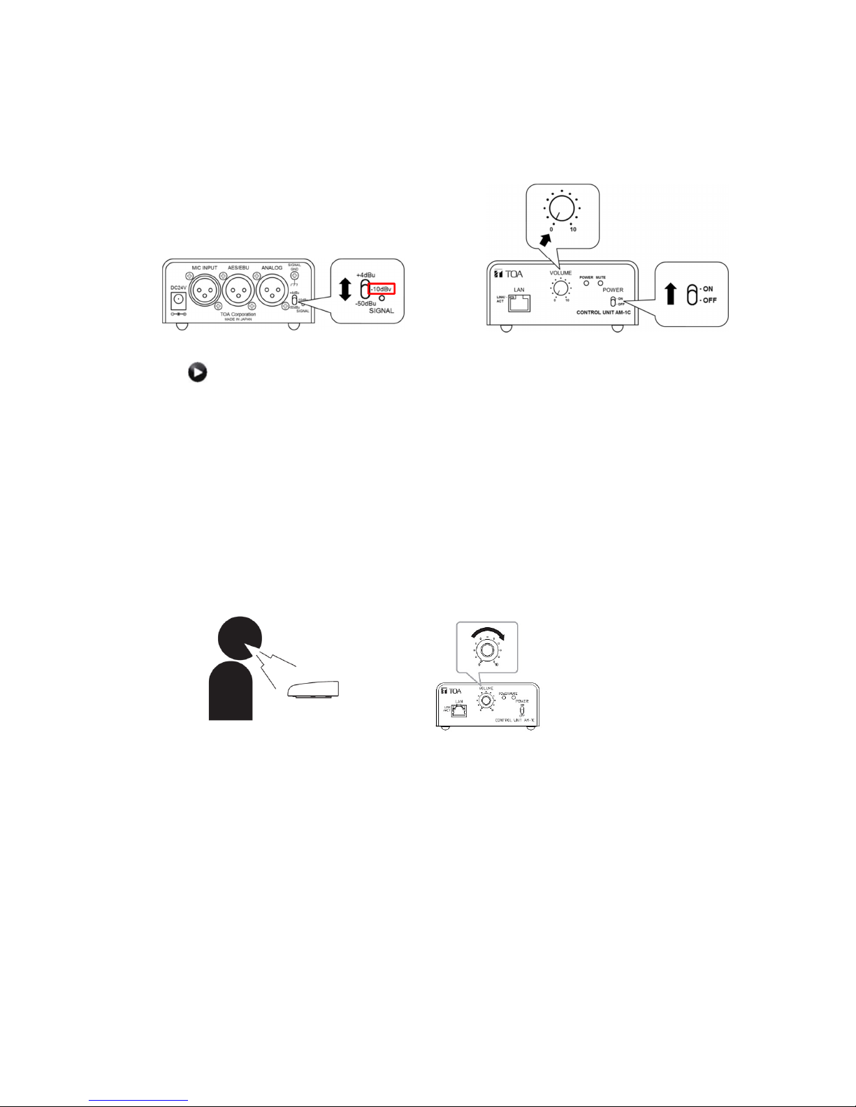
SETTINGS
Step1.
Step2.
Step3.
In the web interface, go to
Step4.
Step5.
Step6.
Step7.
Step8.
Confirm all devices are connected properly as shown above.
Make sure that the audio output level of the AM-1 Control Unit is set to “-10dBv” and the volume
control is set to “0”.
In the local interface of HDX 9000, go to
(select if necessary).
or
Select Input Type to
Enable
Make sure that the
Adjust the
While speaking to the microphone from an appropriate distance, adjust the output level with the
volume control. The
Echo Canceller
Input Type Level
Line Input
.
Phantom Power
Audio Meter
System > Admin Settings > Audio > Inputs/Outputs
Admin Settings > Audio.
. (Only for 9004/9902/9001)
is NOT enabled. (Only for 9004/9002/9001)
if necessary.
on HDX 9000 should peak at about 5 dB for normal speech.
9
Page 10

8. SPECIFICATIONS OF AM-1
MICROPHONE
Power Source 24V DC/200mA (supplied from Control Unit)
Maximum Input Sound Level 100dB SPL (at 20" distance)
S/N Ratio 90dB or more (from Control Unit)
Frequency Response 150 - 18,000Hz
Directional Angle Horizontal: 50°(450 - 18,000Hz, Array mode), 180°(Cardioid mode)
Vertical: 90°
Mute Switch Touch sensor
LED Indicator In operation (blue)
Cable STP ASE/EBU digital audio cable
Maximum Cable Length from
Control Unit
Dimensions 19.0”(W) x 0.8”(H) x 2.6”(D) (482 x 20 x 65mm)
Weight 2.4 lb (1.1kg)
CONTROL UNIT
Power Source 24V DC/400mA, from an optional AD-246 AC adapter
S/N Ratio 90dB over
Microphone Input Dedicated input for Microphone Unit, XLR-3-31 equivalent
Audio Output Analog: +4dBu ,-10dBV, -50dBu (selectable), XLR-3-32 equivalent
Digital: AES/EBU 24bit 110Ω, XLR-3-32 equivalent
Control Output volume control, Output level adjustment
LED Indicator Power (blue), Mute (red)
Ethernet 100/10Mbps (Category 5, RJ45 jack), TCP/IP HTTP
Dimensions 4.1”(W) x 1.9”(H) x 8.7”(D) (105 x 48 x 221mm)
Weight 1.3 lb (0.6kg)
230ft (70m)
10
 Loading...