

Page 1
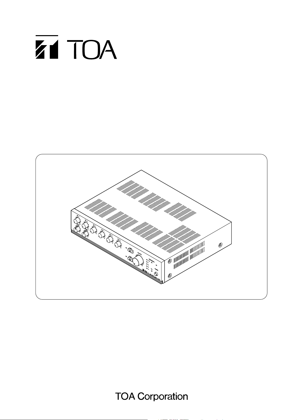
OPERATING INSTRUCTIONS
PA AMPLIFIER A-1803
A-1806
A-1812
Please follow the instructions in this manual to obtain the optimum results from this unit.
We also recommend that you keep this manual handy for future reference.
Page 2

2
TABLE OF CONTENTS
1. SAFETY PRECAUTIONS ................................................................................ 3
2. GENERAL DESCRIPTION ............................................................................. 4
3. FEATURES .......................................................................................................... 4
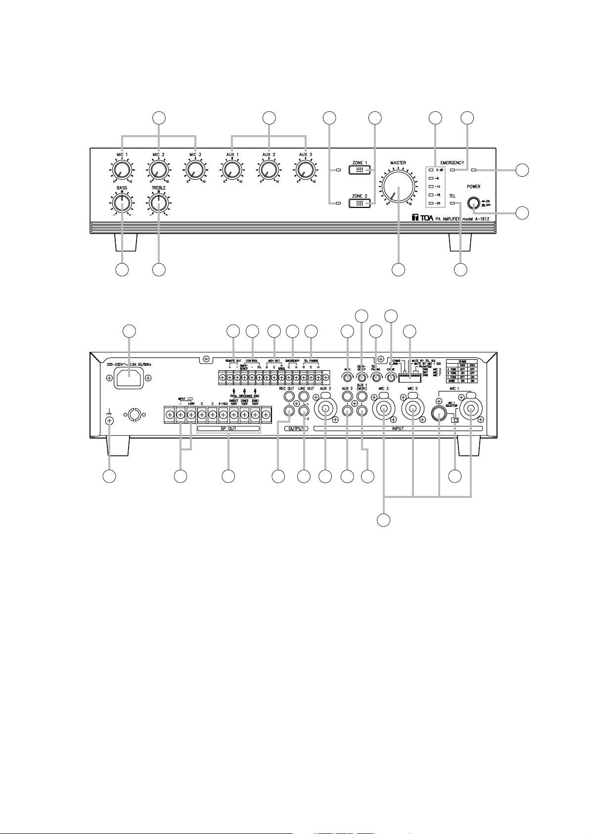
4. NOMENCLATURE AND FUNCTIONS
Front ......................................................................................................................... 5
Rear .......................................................................................................................... 5
5. CONNECTIONS
5.1. Speaker Connections ........................................................................................ 7
5.2. Remote Power ON/OFF Control Connection .................................................... 7
5.3. Emergency Input and Control Input Terminal Connections ............................... 8
5.4. Telephone Paging Input Terminal Connection .................................................. 9
6. FUNCTION SWITCH SETTINGS ................................................................. 9
7. CHIME FUNCTION
7.1. MIC 1 Chime Tone ............................................................................................ 9
7.2. Telephone Paging Chime Tone ......................................................................... 9
8. PRIORITY FUNCTIONS
8.1. Telephone Paging Input (voice-activated priority) ............................................ 10
8.2. Microphone Input (voice-activated priority) ...................................................... 10
8.3. Paging Microphone Input ................................................................................. 10
8.4. Emergency Control Input .................................................................................. 10
8.5. Telephone Paging Control Input ....................................................................... 10
9. SPEAKER ZONE SELECTION .................................................................... 11
10. INSTALLATION ................................................................................................. 11
11. RACK MOUNTING ........................................................................................... 11
12. CONTROL SETTINGS .................................................................................... 12
13. DIMENSIONAL DIAGRAM ............................................................................ 12
14. INTERNAL MODIFICATIONS
14.1. Turning On/Off LINE OUT 1 (2) in conjunction
with ZONE 1 (2) Selector Switch .................................................................... 13
14.2. Turning the Power Off to Disable Broadcast
with EMRGENCY Control Activation .............................................................. 13
14.3. Convert TEL PAGING Input into Transformer-Balanced Type ....................... 13
15. BLOCK DIAGRAM ........................................................................................... 14
16. SPECIFICATIONS ............................................................................................ 15
Accessories ............................................................................................................. 16
Optional products .................................................................................................... 16
Page 3
3
1. SAFETY PRECAUTIONS
• Be sure to read the instructions in this section carefully before use.
• Make sure to observe the instructions in this manual as the conventions of safety symbols and messages
regarded as very important precautions are included.
• We also recommend you keep this instruction manual handy for future reference.
Safety Symbol and Message Conventions
Safety symbols and messages described below are used in this manual to prevent bodily injury and property
damage which could result from mishandling. Before operating your product, read this manual first and
understand the safety symbols and messages so you are thoroughly aware of the potential safety hazards.
WARNING
Indicates a potentially hazardous situation which, if mishandled, could
result in death or serious personal injury.
Indicates a potentially hazardous situation which, if mishandled, could
result in moderate or minor personal injury, and/or property damage.
WARNING
CAUTION
When Installing the Unit
• Do not expose the unit to rain or an environment
where it may be splashed by water or other liquids,
as doing so may result in fire or electric shock.
• Use the unit only with the voltage specified on the
unit. Using a voltage higher than that which is
specified may result in fire or electric shock.
• Do not cut, kink, otherwise damage nor modify the
power supply cord. In addition, avoid using the
power cord in close proximity to heaters, and never
place heavy objects -- including the unit itself -- on
the power cord, as doing so may result in fire or
electric shock.
• Be sure to replace the unit's terminal cover after
connection completion. Because high voltage is
applied to the speaker terminals, never touch these
terminals to avoid electric shock.
• Be sure to ground to the safety ground (earth)
terminal to avoid electric shock. Never ground to a
gas pipe as a catastrophic disaster may result.
• Avoid installing or mounting the unit in unstable
locations, such as on a rickety table or a slanted
surface. Doing so may result in the unit falling
down, causing personal injury and/or property
damage.
When the Unit is in Use
• Should the following irregularity be found during
use, immediately switch off the power, disconnect
the power supply plug from the AC outlet and
contact your nearest TOA dealer. Make no further
attempt to operate the unit in this condition as this
may cause fire or electric shock.
· If you detect smoke or a strange smell coming
from the unit.
· If water or any metallic object gets into the unit
· If the unit falls, or the unit case breaks
· If the power supply cord is damaged (exposure of
the core, disconnection, etc.)
· If it is malfunctioning (no tone sounds.)
• To prevent a fire or electric shock, never open nor
remove the unit case as there are high voltage
components inside the unit. Refer all servicing to
your nearest TOA dealer.
• Do not place cups, bowls, or other containers of
liquid or metallic objects on top of the unit. If they
accidentally spill into the unit, this may cause a fire
or electric shock.
• Do not insert nor drop metallic objects or
flammable materials in the ventilation slots of the
unit's cover, as this may result in fire or electric
shock.
When Installing the Unit
• Never plug in nor remove the power supply plug
with wet hands, as doing so may cause electric
shock.
• When unplugging the power supply cord, be sure
to grasp the power supply plug; never pull on the
cord itself. Operating the unit with a damaged
power supply cord may cause a fire or electric
shock.
• When moving the unit, be sure to remove its power
supply cord from the wall outlet. Moving the unit
with the power cord connected to the outlet may
cause damage to the power cord, resulting in fire or
electric shock. When removing the power cord, be
sure to hold its plug to pull.
CAUTION
Page 4

4
• Do not block the ventilation slots in the unit's cover.
Doing so may cause heat to build up inside the unit
and result in fire.
• Avoid installing the unit in humid or dusty locations,
in locations exposed to the direct sunlight, near the
heaters, or in locations generating sooty smoke or
steam as doing otherwise may result in fire or
electric shock.
When the Unit is in Use
• Do not place heavy objects on the unit as this may
cause it to fall or break which may result in
personal injury and/or property damage. In
addition, the object itself may fall off and cause
injury and/or damage.
• Make sure that the volume control is set to
minimum position before power is switched on.
Loud noise produced at high volume when power is
switched on can impair hearing.
• Do not operate the unit for an extended period of
time with the sound distorting. This is an indication
of a malfunction, which in turn can cause heat to
generate and result in a fire.
• Contact your TOA dealer as to the cleaning. If dust
is allowed to accumulate in the unit over a long
period of time, a fire or damage to the unit may
result.
• If dust accumulates on the power supply plug or in
the wall AC outlet, a fire may result. Clean it
periodically. In addition, insert the plug in the wall
outlet securely.
• Switch off the power, and unplug the power supply
plug from the AC outlet for safety purposes when
cleaning or leaving the unit unused for 10 days or
more. Doing otherwise may cause a fire or electric
shock.
2. GENERAL DESCRIPTION
Equipped with Priority function, Chime function, and 2 Zone selector switches, TOA's A-1803, A-1806, and A1812 PA Amplifiers are designed to suit PA system applications such as paging announcements,
intercommunications, BGM and broadcasting in schools, offices and shops.
3. FEATURES
• Power output of 30 W (A-1803), 60 W (A-1806), and 120 W (A-1812).
• Built-in chime unit (1-tone chime, 2-tone chime, and ascending 4-tone chime)
• Chime can be sounded on use of the MIC 1 input (an optional PM-660D Paging Microphone connectable) or
on Telephone paging.
• Priority function provided for inputs as follows:
Emergency input has the highest priority to all inputs. (Contact activation)
Telephone Paging input has precedence over the inputs other than Emergency input.
MIC 1 input has precedence over the inputs other than Emergency and Telephone Paging inputs.
• Emergency function performs as follows:
Closing the contact at the Emergency Control input terminals turns ON the unit's power even if it is OFF, and
both Zone selector switches.
• Following audio signal inputs suitable for the intended applications: 3 Microphone inputs, 3 AUX inputs, 1
Emergency input, and 1 Telephone Paging input.
• Phantom-powered Microphone inputs (power ON/OFF switchable).
• Combined XLR/phone jack Microphone inputs for convenient use.
• Electronically-balanced Microphone inputs.
• Speaker selectors for 2-zone broadcast.
• Tone controls (bass and treble).
• Output level meter.
• Master volume control for overall input (excluding the Emergency input) signal level adjustment.
• AC and DC power source.
An all-pole mains switch with a contact separation of at least 3 mm in each pole shall be incorporated in
the electrical installation of the building.
Page 5
5
4. NOMENCLATURE AND FUNCTIONS
1. Power switch
Press to turn ON the power.
Press again to turn the power OFF.
2. Power indicator
Lights green when the power is switched on.
3. Microphone volume controls [MIC 1 – 3]
Adjust the microphone level.
4. AUX volume controls [AUX 1 – 3]
Adjust the AUX level.
5. Bass control
Adjusts bass response. Rotate clockwise to
increase bass output, and counterclockwise to
reduce it. The center position provides flat
characteristics.
6. Treble control
Adjusts treble response. Rotate clockwise to
increase treble output, and counterclockwise to
reduce it. The center position provides flat
characteristics.
7. Zone indicators
Light to indicate the broadcast zone (zone1, 2)
selected with the Zone selector switches.
Both Zone selector switches (8) are turned on
(their indicators are lit), even if off, while the
EMERGENCY or TEL control input terminals
(18) remain shorted.
8. Zone selector switches
Select the desired broadcast zone. Pressing the
ZONE 1 switch allows the ZONE 1 output
terminal (16) to output signals. Similarly,
pressing the ZONE 2 switch allows the ZONE 2
output terminal to output signals.
9. Master volume control
Adjusts the overall signal level.
10. LED level meter
Indicates an output level.
11. Emergency indicator
Lights red when the unit is in Emergency mode.
[Front]
[Rear]
This figure represents the A-1812.
3
5 6
This figure represents the A-1812.
13
4
7 8
10 11
2
1
9
12
32
18 1917
20
21
293031
33
14 15 16
22 23
24 25 26
28
27
Page 6

6
12. Telephone paging indicator
Lights green when the unit is in Telephone
paging mode.
13. AC inlet
Connects to the supplied power cord.
14. Ground terminal
A functional ground terminal.
15. DC input terminals
Connect to a 24 V DC power supply.
16. Output terminals
Connect to speakers. Output signals from the
ZONE 1 and 2 output terminals when the frontmounted ZONE 1 and 2 switches (8) are
pressed, respectively. Emergency or telephone
paging input signals are outputted from both
ZONE 1 and 2 terminals irrespective of their
selector switch settings while the EMERGENCY
or TEL control input terminals (18) remain
shorted. The DIRECT output terminal
continuously outputs signals irrespective of these
switch settings.
17. Remote control output terminals
[REMOTE OUT]
Provide an open collector output, which is
designed specifically to remotely control the
optional P-1812 PA Amplifier's power ON/OFF.
18. Control input terminals [CONTROL]
Accept make contacts to give a priority to the
Telephone Paging input or Emergency input.
19. MOH (Music On Hold) output terminals
[MOH OUT]
0 dB, 600 Ω, balanced.
Connect to the telephone system. Output signals
fed to the AUX 1 (MOH) input (26).
The MOH output will not be subject to the mute
control activations through the Emergency and
TEL control input terminals, and MIC 1 input
terminal.
20. Emergency input terminals [EMERGENCY]
0 dB, 10 kΩ, unbalanced.
An Emergency broadcast input.
21. Telephone paging input terminals
[TEL PAGING]
–20 dB, 10 kΩ, electronically-balanced.
Can be converted into transformer-balanced by
internal modification.
For modification, refer to p. 13.
22. Recording output terminals [REC OUT]
0 dB, 600 Ω, unbalanced.
Output the signal before the master volume
control. Connect a cassette deck, etc. when
recording the broadcast contents.
23. Line output terminals [LINE OUT 1, 2]
0 dB, 600 Ω, unbalanced.
Connect to the line input of other equipment.
Continuously outputs signals irrespective of the
zone selector switch settings. (Factory-preset)
Internal modification can change this operation
as follows:
Turning on/off the LINE OUT 1 and 2 can be
interlocked with the Zone 1 and 2 selector
switches, respectively.
For this modification (p. 13 for details), please
consult your TOA dealer.
24. AUX 3 input terminal [AUX 3]
–20 dB, 10 kΩ, unbalanced.
A combined XLR (female)/phone jack connector.
Accepts external equipment output signals.
25. AUX 2 input terminal [AUX 2]
–20 dB, 10 kΩ, unbalanced.
Accepts external equipment output signals.
26. AUX 1 (MOH) input terminal [AUX 1 (MOH)]
–20 dB, 10 kΩ, unbalanced.
Accepts external equipment output signals.
Signals fed to this terminal are outputted from
the MOH output terminals as well.
27. Microphone input terminals [MIC 1 – 3]
–60 dB, 600 Ω, electronically balanced.
Combined XLR (female)/phone jack connectors.
The MIC 1 has an additional DIN connector for
connection of an optional PM-660D Paging
Microphone.
28. MIC 1 terminal selector switch
Shifting the switch to the right enables the use of
combined XLR (female)/phone jack connector,
while shifting it to the left enables the DIN
connector.
29. MOH volume control
Adjusts the MOH output volume independently of
the AUX 1volume control (4).
30. Emergency volume control
Adjusts the Emergency output volume.
31. Telephone paging volume control
[TEL PAGING]
Adjusts the Telephone Paging output volume.
32. Chime volume control [CHIME]
Adjusts the sound volume of the unit's built-in
chime.
33. Function switch
An 8-bit DIP switch. Selects the following
functions:
(1) Phantom power ON/OFF for each MIC 1–3
(2) ON/OFF for the MIC 1 voice-activated priority
(3)ON/OFF for the Telephone Paging voice-
activated priority
(4)Selecting one from 3 different types of chime
tones (4-tone chime/2-tone chime/1-tone chime),
or chime OFF.
Usable connectors and plugs
• XLR type male connector
• Phone plug
Pin 1: Ground
Sleeve: Ground
Pin 2: Hot
Tip: Hot
Pin 3: Cold
Ring: Cold
Page 7

7
Be sure to attach the supplied terminal cover after connection completion. Because high voltage is
applied to the speaker terminals, never touch these terminals to avoid electric shock.
5. CONNECTIONS
5.1. Speaker Connections
WARNING
5.2. Remote Power ON/OFF Control Connection
The optional P-1812 PA Amplifier's power can be remotely switched ON or OFF with the power switch
operation of the A-1800 series. (This remote control operates only when the P-1812's power is OFF.)
Make the Remote IN-OUT terminal connections as shown below.
INPUT
24 V
CC
4
16Ω
DIRECT
100 V
ZONE 2
100 V
ZONE 1
100 V
INPUT
24 V
CC
4 16Ω
DIRECT
100 V
ZONE 2
100 V
ZONE 1
100 V
Total impedance
330 Ω (A-1803)
167 Ω (A-1806)
83 Ω (A-1812)
4 – 16 Ω
Notes
100 V line
100 V line
• Both the 4 – 16 Ω and 100 V terminals cannot be used
at the same time.
• Impedances indicated in the figures represent the total
100 V line
speaker system (load) impedances.
A-1803
A-1806
A-1812
REMOTE OUT
REMOTE IN CONTROL
REMOTE IN CONTROL
EMERGENCY
EMERGENCY
P-1812
P-1812
Page 8

8
5.3. Emergency Input and Control Input Terminal Connections
While the Emergency control input terminals remain shorted, the power of all the connected A-1800 series
and P-1812s is turned on, and the A-1800's ZONE 1 and 2 speaker outputs are enabled, allowing only
Emergency input signals to go through bypassing the master volume control.
Opening the control input terminals automatically returns the muted signals to the original level.
A-1803
A-1806
A-1812
Connect this cable when requiring
remote power ON/OFF control.
P-1812
REMOTE OUT CONTROL EMERGENCY
EMERGENCY
REMOTE IN CONTROL
EMERGENCY
TEL C
REC OUT
LINE OUT
LINE OUT
1
2
LINE IN
H
P-1812
REMOTE IN CONTROL
EMERGENCY
LINE OUT
LINE IN
Page 9

9
5.4. Telephone Paging Input Terminal Connection
Phantom Power
Switch No.
Function
OFF
ON
1
unused
unused
4
TEL PAGING
Voice-activated
Priority
OFF
ON
5
MIC 1
Voice-activated
Priority
OFF
ON
6
MIC 3
OFF
ON
7
MIC 2
OFF
ON
8
MIC 1
OFF
ON
23
Chime Selection
See the Chime
Selection Table below.
6. FUNCTION SWITCH SETTINGS
Set the rear-mounted Function switch as shown below.
Switch No.
23
OFF OFF
ON OFF
OFF ON
ON ON
Chime Tone
4-Tone Chime
2-Tone Chime
1-Tone Chime
OFF
[Chime Selection Table]
7. CHIME FUNCTION
7.1. MIC 1 Chime Tone
When using the MIC 1's DIN plug, shorting its Pins 4 and 5 allows the chime of type selected with the
Function switch setting to sound.
7.2. Telephone Paging Chime Tone
Shorting the Telephone Paging Control input terminals allows the chime of type selected with the Function
switch setting to sound.
TEL PAGING
CGH
When using a single-core shielded cable,
connect the shield mesh to both G and C terminals.
CGH
12ON345678
Page 10

10
8. PRIORITY FUNCTIONS
8.1. Telephone Paging Input (voice-activated priority)
With the Function switch No. 4 set to ON, voices applied to the Telephone Paging input terminals mute the
input signals other than Telephone paging and Emergency input signals.
After completion of the paging announcements, the muted signals automatically return to the original level.
8.2. Microphone Input (voice-activated priority)
With the Function switch No. 5 set to ON, voices applied to the MIC 1 input terminal mute the input signals
other than MIC 1, Telephone Paging, and Emergency input signals.
After completion of the microphone announcements, the muted signals automatically return to the original
level.
8.3. Paging Microphone Input
With the MIC 1 terminal selector switch set to the
left position (DIN connector input), shorting the
connector Pins 4 and 5 sounds the chime of type
selected with the Function switch setting and
mutes the input signals other than MIC 1,
Telephone Paging, and Emergency input signals.
Opening the Pins 4 and 5 automatically returns the
muted signals to the original level.
8.4. Emergency Control Input
Shorting the Emergency Control input terminals
turns on the power, even if off, and enables both
ZONE 1 and 2 speaker outputs, muting all input
signals other than the Emergency input signals,
which go through bypassing the master volume
control.
Opening the control input terminals automatically
returns the muted signals to the original level.
Internal modification can change this Emergency
control function as follows:
Shorting the control terminals forces the power to
turn off, disabling broadcast from the unit.
Opening the terminals returns the unit operation to
the original broadcast status.
For this modification (p. 13 for details), please
consult your TOA dealer.
8.5. Telephone Paging Control Input
Shorting the Telephone Paging Control input
terminals sounds the chime of type selected with
the Function switch setting and enables both
ZONE 1 and 2 speaker outputs, muting the input
signals other than Telephone Paging and
Emergency input signals.
Opening the control input terminals automatically
returns the muted signals to the original level.
2
5
3 1
4
Muting switch
To hot line of microphone
To common (shielded) line of microphone
To cold line of microphone
CONTROL
EMERGENCY
CONTROL
EMERGENCY
TEL
TEL
Page 11

11
9. SPEAKER ZONE SELECTION
Pressing the front-mounted ZONE 1 switch permits its zone indicator to light and makes broadcast through the
speakers connected to the rear-mounted Zone 1 output terminals.
Operation for ZONE 2 is performed in the same way as above.
Shorting the Emergency Control or Telephone Paging Control input terminals turns on both Zone 1 and 2
switches (their indicators light), even if off, allowing the Emergency or Telephone Paging input signals to be
broadcast from both ZONE 1 and 2 speaker outputs.
Opening the control input terminals automatically returns the operation to the original status.
10. INSTALLATION
Keep the unit's all sides over 10 cm away from objects that may obstruct air flow to prevent the unit's internal
temperature rise.
11. RACK MOUNTING
To mount the unit in a standard 19" equipment rack, use the optional MB-25B Rack Mounting Bracket.
Attach the MB-25B to the unit using the supplied 4 screws. When using other screws, each screw must be
shorter than 16 mm.
Over 10 cm
Over 10 cm
Over 10 cm
M4 x 16 Machine screw
included in MB-25B
MB-25B
Page 12

12
13. DIMENSIONAL DIAGRAM (Applicable to all models)
12. CONTROL SETTINGS
Output levels are adjustable with individual volume controls. For music play or announcements, adjust the
corresponding volume control so that the red indicator doesn't light. Note that the sound quality is downgraded
when the red indicator remains lit.
To prevent the accidental change of the settings of input volume and tone (Bass and Treble) controls, remove
their knobs after setting them to the desired position and attach the optional YA-920 Volume Control Covers
instead.
MIC 2
MIC 1
BASS
YA-920 (optional)
Control knob
88.4
107.7
Unit: mm
367420
326.518.5
Page 13

13
14. INTERNAL MODIFICATIONS
Leave the modifications described here to a qualified service technician only.
Please consult your TOA dealer.
14.3. Convert TEL PAGING Input into Transformer-Balanced Type
Step 1. Cut the jumpers SJP400 and SJP401.
Note: Treat the cut jumper pieces, especially SJP400's
pieces, so that they will not touch the transformer
case to be installed in the next step.
Step 2. Install and solder the optional IT-453A Input Transformer in place of "T400" indication on the Control
circuit board.
14.2. Turning the Power Off to Disable Broadcast with EMRGENCY Control Activation
Install the SJP102 jumper to "OFF" position.
14.1. Turning On/Off LINE OUT 1 (2) in conjunction with ZONE 1 (2) Selector Switch
• To interlock LINE OUT 1 with ZONE 1 switch, install the
SJP100 jumper to "ON" position.
• To interlock LINE OUT 2 with ZONE 2 switch, install the
SJP101 jumper to "ON" position.
[Upper view without case]
SJP400 and SJP401 "T400" for mounting the IT-453A
Control circuit board
Rear panel
SJP100 (ZONE 1)
SJP101 (ZONE 2)
Main circuit board
SJP102 (EMERGENCY)
SJP100 (ZONE 1)
SJP101 (ZONE 2)
OFF
Jumper
OFF
ON
Factory-preset position
ON
Jumper
SJP102 (EMERGENCY)
ON OFFON
Factory-preset position
OFF
SJP401 SJP400
Page 14

14
15. BLOCK DIAGRAM
REC OUT
0 dB/600 Ω
BASS/TREBLE
LINE OUT
0 dB/600 Ω
1
2
MASTER
0 dB
volume
Interlocked with
Relay 1 (ZONE 1)
ON
OFF
ON
OFF
Interlocked with
Relay 2 (ZONE 2)
ZONE 1 (100 V)
ZONE 2 (100 V)
(Relay 1)
(Relay 2)
(70 V)
(50 V)
OT
PA
DIRECT (100 V)
4 – 16 Ω
C
C
JP
INPUT
+ 24 V
–
Output
level meter
Power for
audio section
A-1812 only
PT
Fuse
240 V
230 V
Fuse Fuse
Emergency
Power for
mode ON/OFF
control section
TEL
220 – 230 V AC
or 240 V AC,
50/60 Hz
EMERGENCY
POWER
switch
POWER
Function switch (DIP swich)
0 dB
Chime tone selection
TEL voice-activated mute ON/OFF
87654321
ON
–20 dB
MIC 1 voice-activated mute ON/OFF
Phantom power ON/OFF
EB
Mute
Mute
–20 dB
EB
Mute control
(TEL, EMER)
(MIC 1)
Mute control
–20 dB
EB
Power for
chime circuit
–20 dB
0 dB
1
Relay
2
Relay
EB
Zone 2 Zone 1
Mute control
0 dB
ZONE 2 ZONE 1
Chime
Phantom
power
MIC 2
–60 dB/600 Ω
+
H
MIC 3
–60 dB/600 Ω
AUX 1 (MOH IN)
–20 dB/10 kΩ
AUX 2
–20 dB/10 kΩ
AUX 3
–20 dB/10 kΩ
Optional
H
C
G
EMERGENCY
TEL PAGING
0 dB/10 kΩ
– 20 dB/10 kΩ
C
H
C
MOH OUT
0 dB/600 Ω
G
+
TEL
CONTROL
–
+
+
EMERGENCY
–
REMOTE OUT
+
MIC 1
MIC 1
–60 dB/600 Ω
+
SELECTOR
Page 15

15
16. SPECIFICATIONS
Model No. A-1803 A-1806 A-1812
Power Source 220 – 230 V AC or 240 V AC, 50/60 Hz
24 V DC (M4 screw terminal*1)
Rated Output 30 W 60 W 120 W
Power/Current Consumption AC operation: AC operation: AC operation:
80 W (rated output), 158 W (rated output), 260 W (rated output),
37 W (EN60065) 66 W (EN60065) 110 W (EN60065)
24 V DC operation: 24 V DC operation: 24 V DC operation:
2.0 A (rated output), 3.8 A (rated output), 7.0 A (rated output),
1.0 A (EN60065) 1.6 A (EN60065) 2.8 A (EN60065)
Frequency Response 50 – 20,000 Hz (±3 dB)
Distortion Under 2% at 1 kHz, rated power
Input MIC 1: –60 dB*2, 600 Ω, electronically-balanced, combined type of
XLR-3-31 equivalent and phone jack, DIN socket (5 pins)
MIC 2 – 3: –60 dB*2, 600 Ω, electronically-balanced, combined type of
XLR-3-31 equivalent and phone jack
AUX 1 (MOH): –20 dB*2, 10 kΩ, unbalanced, RCA pin jack
AUX 2: –20 dB*2, 10 kΩ, unbalanced, RCA pin jack
AUX 3: –20 dB*2, 10 kΩ, unbalanced, combined type of XLR-3-31
and phone jack
TEL*3: – 20 dB*2, 10 kΩ , electronically-balanced, M3 screw
terminal*
1
EMERGENCY: 0 dB*2, 600 Ω, unbalanced, M3 screw terminal*
1
Output REC: 0 dB*2, 600 Ω, unbalanced, RCA pin jack
LINE 1, 2*4: 0 dB*2, 600 Ω, unbalanced, RCA pin jack
MOH: 0 dB*2, 600 Ω, transformer balanced, M3 screw
terminal*
1
SPEAKER SELECTOR: 2 zone, high impedance*5(100 V line), individual
selector switch, M4 screw terminal*
1
DIRECT SPEAKER OUT:
High impedance*5(100 V line), M4 screw terminal*1,
Low impedance (4 – 16 Ω), M4 screw terminal*
1
Note: Both Low and High impedance terminals cannot be used at the same time.
Phantom Power ON or OFF for each MIC 1 – 3 with switch setting
S/N Ratio Over 100 dB (Master volume: min)
(Band Pass: 20 – 20,000 Hz) Over 76 dB (Master volume: max)
Over 60 dB (MIC 1 – MIC 3)
Over 76 dB (AUX 1 – AUX 3)
Over 90 dB (TEL)
Over 96 dB (EMERGENCY)
Tone Control Bass: ±10 dB at 100 Hz, Treble: ±10 dB at 10 kHz
Control Input TEL: No-voltage make contact input
Open voltage: 24 V DC
Short-circuit: under 5 mA, M3 screw terminal*
1
EMERGENCY*6: No-voltage make contact input
Open voltage: 24 V DC
Short-circuit: under 10 mA, M3 screw terminal*
1
Control Output Power remote: Open collector output
Withstand voltage: 35 V DC
Control current: under 50 mA, M3 screw terminal*
1
Chime 1-tone, 2-tone, or ascending 4-tone chime, or None selectable with switch
setting, activated at MIC 1's DIN or CONTROL TEL terminal.
Indicator 5-point LED output level meter, Power indicator LED, Zone indicator LEDs,
Emergency LED, TEL LED
Page 16

133-12-846-60
*
1
Distance between barriers on the above screw terminals: 7 mm (M3 screw), 9 mm (M4 screw)
*
2
0 dB = 1 V
*
3
Can be transformer-balanced with the addition of optional IT-453A input transformer.
*
4
LINE 1 and LINE 2 outputs can be interlocked with ZONE 1 and ZONE 2 speaker selectors, respectively.
*
5
330 Ω (A-1803), 167 Ω (A-1806), 83 Ω (A-1812)
*
6
Operation when activated can be selected from the following: Turning ON the unit's power (factory-preset) or OFF.
Note: The design and specifications are subject to change without notice for improvement.
• Accessories
AC power cord ................................................... 1
Terminal cover ................................................... 1
Terminal cover mounting screw (M4 x 8) ........... 2
• Optional products
Rack mounting bracket: MB-25B
Volume control cover: YA-920
Input transformer: IT-453A (Available as a service part, whose part code is "114-03-118-30.")
Model No. A-1803 A-1806 A-1812
Priority EMERGENCY: Overrides other inputs
TEL: Overrides other inputs except 'EMERGENCY', ON/OFF
selectable with switch setting
MIC 1: Overrides other inputs except 'EMERGENCY' and TEL',
ON/OFF selectable with switch setting
Operating Temperature –10°C to +40°C
Finish Panel: ABS resin, black, hair line
Case: Steel plate, black
Dimensions 420 (w) x 107.7 (h) x 367 (d) mm
Weight 8.1 kg 9.4 kg 12.6 kg
 Loading...