

Page 1
Please follow the instructions in this manual to obtain the optimum results from this unit.
We also recommend that you keep this manual handy for future reference.
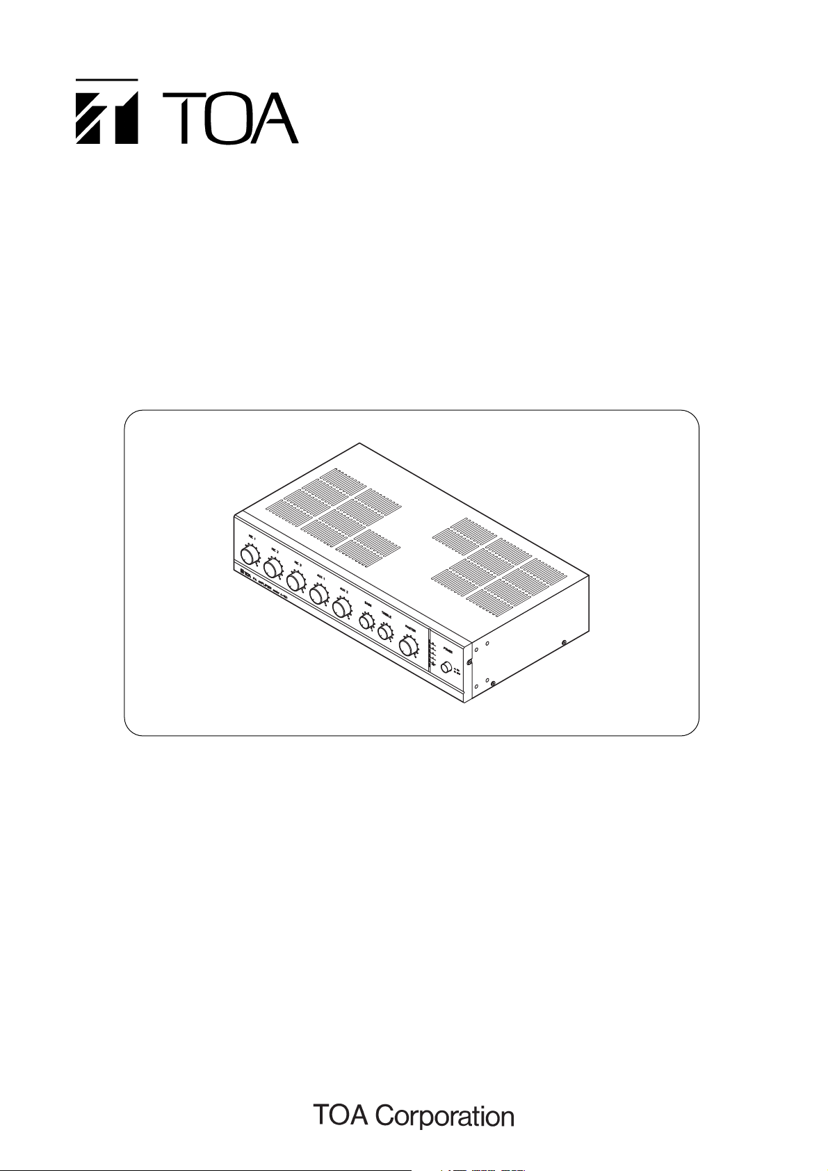
A-1031
A-1061
A-1121
BASIC PA AMPLIFIER
OPERATING INSTRUCTIONS
TABLE OF CONTENTS
1. SAFETY PRECAUTIONS .............................. 2
2. GENERAL DESCRIPTION ............................ 3
3. FEATURES .................................................... 3
4. PANEL FACILITIES ....................................... 3
5. MUTING FUNCTION ..................................... 4
6. CONNECTION EXAMPLE ............................. 5
7. DIMENSIONAL DIAGRAM ............................ 6
8. BLOCK/LEVEL DIAGRAM ............................ 7
9. SPECIFICATIONS ......................................... 8
Page 2
2
1. SAFETY PRECAUTIONS
• Be sure to read the instructions in this section carefully
before use.
• Make sure to observe the instructions in this manual as
the conventions of safety symbols and messages
regarded as very important precautions are included.
• We also recommend you keep this instruction manual
handy for future reference.
Safety Symbol and Message Conventions
Safety symbols and messages described below are used
in this manual to prevent bodily injury and property
damage which could result from mishandling. Before
operating your product, read this manual first so you are
thoroughly aware of the potential safety hazards as well as
understand the safety symbols and messages.
When Installing the Unit
• Do not expose the unit to rain or an environment where it
may be splashed by water or other liquids, as doing so
may result in fire or electric shock.
• Use the unit only with the voltage specified on the unit.
Using a voltage higher than that which is specified may
result in fire or electric shock.
• Do not cut, kink, otherwise damage nor modify the power
supply cord. In addition, avoid using the power cord in
close proximity to heaters, and never place heavy
objects -- including the unit itself -- on the power cord, as
doing so may result in fire or electric shock.
• Be sure to replace the unit's terminal cover after
connection completion. Because the voltage of up to 100
V is applied to the high impedance speaker terminals,
never touch these terminals to avoid electric shock.
• Be sure to ground to the safety ground (earth) terminal to
avoid electric shock. Never ground to a gas pipe as a
catastrophic disaster may result.
When the Unit is in Use
• Should the following irregularity be found during use,
immediately switch off the power, disconnect the power
supply plug from the AC outlet and contact your nearest
TOA dealer. Make no further attempt to operate the unit
in this condition as this may cause fire or electric shock.
· If you detect smoke or a strange smell coming from
the unit.
· If water or any metallic object gets into the unit
· If the unit falls, or the unit case breaks
· If the power supply cord is damaged (exposure of the
core, disconnection, etc.)
· If it is malfunctioning (no tone sounds.)
• To prevent a fire or electric shock, never open nor
remove the unit case as there are high voltage
components inside the unit. Refer all servicing to your
nearest TOA dealer.
• Do not place cups, bowls, or other containers of liquid or
metallic objects on top of the unit. If they accidentally spill
into the unit, this may cause a fire or electric shock.
• Do not insert nor drop metallic objects or flammable
materials in the ventilation slots of the unit's cover, as
this may result in fire or electric shock.
When Installing the Unit
• Never plug in nor remove the power supply plug with wet
hands, as doing so may cause electric shock.
• When unplugging the power supply cord, be sure to
grasp the power supply plug; never pull on the cord itself.
Operating the unit with a damaged power supply cord
may cause a fire or electric shock.
• When moving the unit, be sure to remove its power
supply cord from the wall outlet. Moving the unit with the
power cord connected to the outlet may cause damage
to the power cord, resulting in fire or electric shock.
When removing the power cord, be sure to hold its plug
to pull.
• Do not block the upper panel ventilation slots in the unit's
cover. Doing so may cause heat to build up inside the
unit and result in fire.
• Avoid installing the unit in humid or dusty locations, in
locations exposed to the direct sunlight, near the heaters,
or in locations generating sooty smoke or steam as doing
otherwise may result in fire or electric shock.
When the Unit is in Use
• Do not place heavy objects on the unit as this may cause
it to fall or break which may result in personal injury
and/or property damage. In addition, the object itself may
fall off and cause injury and/or damage.
WARNING Indicates a potentially
hazardous situation which, if mishandled, could result
in death or serious personal injury.
CAUTION
Indicates a potentially hazardous
situation which, if mishandled, could result in moderate or
minor personal injury, and/or property damage.
WARNING
CAUTION
Page 3
3
2. GENERAL DESCRIPTION
TOA's Basic PA Amplifiers A-1031, A-1061, and A-1121 are high cost-performance mixer power amplifiers suited for
broadcasting paging or background music in schools, offices, and shops.
3. FEATURES
• High durability, high reliability, and high cost performance.
• Three microphone inputs, two AUX inputs, and one recording output.
• Speaker outputs of constant voltage distribution system (100 V and 70 V) and low impedance (4 Ω).
• Operates on both AC and DC power.
• Muting function.
• Independent input volume controls and master volume control.
• Independent tone controls cut both high and low frequencies.
• Power voltage selector of 110 – 120 V or 220 – 240 VAC (LH version).
• MIC 1 input is a 5-pin DIN connector to provide muting control and phantom power for condenser microphones. (ER and
UK versions).
• Five-segment output level meter provides at-a-glance monitoring of output status.
• Current limiter circuitry protects transistors, and the thermal protection circuitry prevents a failure due to overheat.
4. PANEL FACILITIES
[Rear panel (AS version)][Front panel]
[Rear panel (LH version)]
[Rear panel (ER/UK versions)]
①②
③
⑥
⑧⑦⑤④ ⑭ ⑫⑬
⑨ ⑩ ⑮
⑪
⑰
⑲
⑭
⑫⑬
⑨ ⑩ ⑮
⑪
⑰
⑱
⑭ ⑫⑬
⑨ ⑩ ⑮
⑪
⑰
⑯
① Power on-off button
Power is switched on and off with each depression of
this button.
② Power indicator
Lights when power is switched on.
③ LED level meter
Lights when power is switched on, and indicates an
output level.
④ Microphone volume control
Adjusts the microphone volume gain.
⑤ AUX volume control
Adjusts the AUX volume gain.
⑥ Master volume control
Adjusts the overall signal gain.
⑦ Bass control
Adjusts bass response. The "0" position provides flat
audio response. Turning this control counter-clockwise
attenuates the bass response.
⑧ Treble control
Adjusts treble response. The "0" position provides flat
audio response. Turning this control counter-clockwise
attenuates the treble response.
Page 4

4
5. MUTING FUNCTION
● H version
When MIC 1 input is used, it takes precedence and automatically reduces the volume of MIC 2 and MIC
3 inputs by 0 to –30 dB, which is adjustable with the MUTE control on the rear panel. The attenuation
level is preset for –30 dB at the factory.
● R and UK versions
Shorting DIN plug pins 4 and 5 of rear-mounted MIC 1 input allows MIC 1 input to reduce the volume of MIC 2 and MIC 3
inputs by 0 to –30 dB. The attenuation level is adjustable with the MUTE control on the rear panel and is preset for –30 dB
at the factory. Use TOA's microphone PM-222D or PM-660D to bring the best results.
● S version
Connect the supplied connector with lead wires to the muting connector on the rear panel, and the lead wires to the
muting switch. Turning on (shorting) the muting switch allows MIC 1 input to take precedence, muting signals of inputs of
MIC 1 and 2, and AUX 1 and 2 by 0 to –30 dB. The attenuation level is adjustable with the rear-mounted muting control,
and is preset for –30 dB at the factory.
1
4
2
5
3
Muting switch
To hot line of microphone
To common (shielded) line of microphone
To cold line of microphone
Muting switch
⑨ AC power cord
Connects to an AC power source.
⑩ DC terminals
Connect to a DC power supply. (A-1031 and A-1061:
12 VDC, A-1121: 24 VDC)
⑪ MIC 1 input (LH version)
Connects to the unbalanced type microphone of 30-600
ohms and with 1/4" phone plug. When this input
receives a signal, the muting function is operated.
(Refer to the next section for the muting function.)
⑪ MIC 1 input (ER/UK versions)
Connects to the balanced type microphone of 30-600
ohms and with 5-pin DIN connector. When pin 4 is
shorted with pin 5, the muting function is operated.
(Refer to the next section for the muting function.)
⑪ MIC 1 input (AS version)
Connects to the balanced type microphone of 30-600
ohms and with XLR connector.
Pin 1: Ground (shield)
Pin 2: Hot (high)
Pin 3: Cold (low)
⑫ MIC 2 and 3 inputs
Connect to the unbalanced type microphone of 30-600
ohms and with 1/4" phone plug.
⑬ AUX 1 and 2 inputs
Connect to auxiliary equipment.
⑭ Recording output
Connect to a cassette tape recorder.
⑮ Output terminals
Connect to speakers.
⑯ Voltage selector (LH version only)
Sets the desired voltage.
⑰ Muting level control
Adjusts the background music volume to be
automatically reduced when the priority function is
operated.
⑱ Phantom power connector (ER/UK versions only)
Inserting this connector into the ON position supplies
power for condenser microphones from MIC 1
connector. Be sure to set this connector to the OFF
position when using the microphone that cannot be
operated on phantom power.
⑲ Muting control connector (AS version only)
Insert the supplied connector to short lead wires
attached to the connector, and the muting function is
operated, allowing MIC 1 input to take precedence.
Notes
• When all the five LEDs (+10 dB) remain lit, this indicates
that sound is distorted. In such a case, adjust each
volume control so that LED 4 (+8 dB) and 5 (+10 dB)
flash.
• When connecting speakers, use only one of the speaker
output terminals.
Page 5

5
6. CONNECTION EXAMPLE
● LH version
AC mains
+
-
12 V DC Battery (A-1031, A-1061)
24 V DC Battery (A-1121)
Horn speaker
Column speaker
Cassette tape recorder
Cassette tape player
or Radio tuner
Microphones (600 Ω, unbalanced)
● R and UK versions
AC mains
+
-
12 V DC Battery (A-1031, A-1061)
24 V DC Battery (A-1121)
Horn speaker
Column speaker
Cassette tape recorder
Cassette tape player
or Radio tuner
Microphones
(600 Ω, unbalanced)
Microphone
(600 Ω, balanced)
*1
*1 Phantom power switch (plug)
The setting position of this phantom plug switches on or off the phantom power to be supplied to MIC 1 input for
condenser microphones. Insert the plug in the position shown in Figure A to switch on the phantom power, and in the
position shown in Figure B to switch it off. The plug is set to the OFF position at the factory. Be sure to check the
microphone specifications when using the phantom power.
PHANTOM PLUG
Fig. A Fig. B
PHANTOM
ON OFF
PHANTOM
ON OFF
Page 6

6
● S version
(Only the functions that differ from those of the ER and UK versions are described here. For connections not described,
refer to the connections of other versions.)
AC mains
Microphone
(600 Ω, balanced)
*2
*2 Muting terminal
Connect the supplied connector plug with lead wires to the muting connector on the rear panel, and the lead wires to the
muting switch. Turning on (shorting) the muting switch allows MIC 1 input to take precedence, muting signals of other
inputs (MIC 1 and 2, and AUX 1 and 2 ).
Muting connector plug
7. DIMENSIONAL DIAGRAM
420
262
230
24 20
8-M4
103
88.4
58.4
15
(unit: mm)
Page 7

7
8. BLOCK/LEVEL DIAGRAM
● H version
MIC1
MIC2
MIC3
AUX1
AUX2
HA
HA
HA
BA BA TC BA
PA
MUTE
AC
MAINS
Low cut High cut
REC OUT
100 V
70 V
4 Ω
COM
30 W, 60 W, 120 W
LEVEL
METER
DC POWER 30 W, 60 W 12 V
• 120 W 24 V
NF
MIC1
MIC2
MIC3
AUX1
AUX2
HA
HA
HA
BA TC
BA
PA
MUTE
AC
MAINS
Low cut High cut
REC OUT
100 V
70 V
4 Ω
COM
30 W, 60 W, 120 W
LEVEL
METER
DC POWER 30 W, 60 W 12 V
• 120 W 24 V
NF
Phantom
EB
MIC1
MIC2
MIC3
AUX1
AUX2
AUX1
HA
HA
HA
BA TC BA
PA
MUTE
AC
MAINS
Low cut High cut
REC OUT
100 V
70 V
4 Ω
COM
30 W, 60 W, 120 W
LEVEL
METER
DC POWER 30 W, 60 W 12 V
• 120 W 24 V
MUTE
NF
MIC1, 2, 3
Power out
100 V line
REC OUT
40 dB
30 dB
20 dB
10 dB
0 dB
-
10 dB
-
20 dB
-
30 dB
-
40 dB
-
50 dB
-
60 dB
EB
● ER and UK versions
● AS version
Page 8

9. SPECIFICATIONS
Note: The design and specifications are subject to change without notice for improvement.
Specifications are measured on 240 VAC power operation.
The LH versions operating voltage is factory-preset at "220 V – 240 VAC".
Model
Output
Output Regulation
Speaker Output
Recording Output
Input
MIC 1 Connector
MIC 1 Phantom Power (ER/UK Versions)
Frequency Response
Distortion
Signal-to-Noise Ratio
Tone Controls
Protection Circuit
Muting Function
Dimensions
Weight
Color
Power
Requirements
Power
Consumption
(at rated output)
Rated
Max.
LH version
LH version
ER
MIC 2, 3
AUX 1, 2: 10 kohms, 100 mV (
-
20 dBV)
1/4" phone jack
5P DIN
3P XLR type
100 – 10,000 Hz (± 3 dB)
Less than 1% at 1 kHz, 1/3 rated power
All volume controls ccw
MASTER max., all input volume min.: 75 dB
MIC 1, 2, and 3
AUX 1 and 2
Bass
Treble: +0 dB,
-
10 dB at 10 kHz
Current limiter, thermal protection, AC & DC fuse
9 VDC 21 VDC
Less than 3 dB, no load to full load
Balanced 4 ohms, 70 V and 100 V
600 ohms, 1 V (0 dBV)
MIC 1, 2, 3: 600 ohms, 1.8 mV (
-
55 dBV) , unbalanced
AUX 1, 2 : 10 kohms, 100 mV (
-
20 dBV) , unbalanced
MIC 1
: 600 ohms, 1.8 mV (
-
55 dBV) , electrical balanced
: 600 ohms, 1.8 mV (
-
55 dBV) , unbalanced
MIC1 overrides other input signals with 0 – 30 dB attenuation
LH version
ER, UK, AS version: 220– 240 V
Black
420 (w) x 103 (h) x 262 (d) mm
AS
AS version
AC 50/60 Hz
DC
AC 50/60 Hz
DC
UK versions
ER, UK versions
A-1031 A-1061 A-1121
30 W 60 W 120 W
45 W 90 W 180 W
120 W 220 W 380 W
5.0 kg 7.5 kg 10 kg
: 92 dB
: 70 dB
: 75 dB
: +0 dB,
-
10 dB at 100 Hz
12 V
5 A 9 A
24 V
: 110 – 120 V or 220 – 240 V (selectable)
 Loading...