

Page 1
Operating Instruction Manual
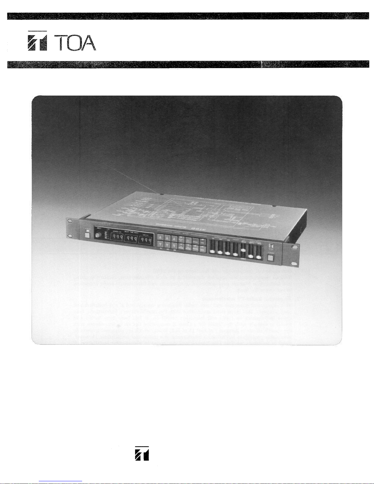
MULTIPLE OUTPUT DIGITAL DELAY
Model 310D
Toa Electric Co., Ltd.
KOBE, JAPAN
Page 2

Contents
Precautions ..................................................................................................1
General Description ....................................................................................2
Features .......................................................................................................2
Front Panel..................................................................................................3
Rear Panel....................................................................................................4
Sample Sounds.......................................................................................5~6
Block Diagram .............................................................................................7
Specifications ..............................................................................................7
Appearance...................................................................................................8
Precautions
1. Description of components and functions on the 310D
Various descriptions are applied, depending on each manufacturer. In our Operating
and Instruction Manual explanation of components and functions is made according
to our usage for them.
2. To prevent Radio-TV interferences
This equipment generates and uses radio frequency energy and if not installed and
used properly, that is, in strict accordance with the manufacturer's instructions, may
cause interference to radio and television reception. It has been type tested and
found to comply with the limits for a Class B computing device in accordance with
the specifications in Subpart J of Part 15 of FCC Rules, which are designed to provide
reasonable protection against such interference in a residential installation. However,
there is no guarantee that interference will not occur in a particular installation. If
this equipment does cause interference to radio or television reception, which can be
determined by turning the equipment off and on, the user is encouraged to try to correct the interference by one or more of the following measures:
...... reorient the receiving antenna
...... relocate this equipment with respect to the receiver
...... move this equipment away from the receiver
...... plug this equipment into a different outlet so that this equipment and receiver
If necessary, the user should consult the dealer or an experienced radio/television
technician for additional suggestions. The user may find the following booklet prepared by the Federal Communications Commission helpful:
"How to Identify and Resolve Radio-TV interference Problems"
This booklet is available from the US Government Printing Office, Washington, D.C.,
20402, Stock No. 004-000-00345-4.
are on different branch circuits
–1 –
Page 3
General Description
The Toa 310D is a multiple output digital delay device that is one vertical rack size,
mountable in a 19-inch EIA rack. Three discrete outputs with different delay times are
obtainable from one input signal. With Toa special circuitry that mixes direct and de-
layed sounds and also reverses the phase of the delayed sounds, the 310D offers flanging, chorus, doubling or echo effects in stereo.
Features
1. Three different time-delayed outputs can be obtained for one input signal.
2. Delay time can be set between 0 and 999 msec, enabling the faithful reproduction of
subtle sound differences and wider chorus effects.
3. It is possible to mix the direct sound with three different time-delayed signals, and
provide the mixed sound from stereo L and R outputs. Also, a wider stereo chorus
effect can be obtained by activating the cross phase switch.
4. Each of the three different time-delayed sounds can be delivered to individual outputs.
5. A maximum of 32 overall settings of each of the three delay times and the on/off
status of the CROSS PHASE, DELAY 2(C) PHASE, REGENERATION (FEEDBACK)
and MODULATION switches can be stored.
6. The modulation IN and OUT jacks permit various timbres to be varied by external
control.
7. Maximum chorus effect can be obtained by using two 310D units and connecting
the "modulation in" terminal of the first unit to the "modulation out" terminal of
next, and the "modulation out" of the first unit to the "modulation in" of the next.
8. Both RCA pin jacks and 1/4" phone jacks are provided for input and output, allow-
ing easy connection of mixers for multi-track recorders.
9. Wide dynamic range provided by the combined method of logarithmic companding
and 12-bit digital signal processing.
10. The 310D has a frequency response from 20Hz to 20kHz (±3dB), enabled by a high
sampling frequency.
11. MIDI In, Out and Thru are provided.
12. A built-in MIDI control function offers access to select specific programs from exter-
nal MIDI equipment.
–2 –
Page 4

Front Panel
Delay time programming key
Pressing this key increases the
programmed delay time in mil-
liseconds. Pressing the key con-
tinuously increases the rate of
change.
Input level indicator LED's
Input level control (INPUT)
This control sets the input signal
level. To use, press and release
the control to make it spring out.
Adjust the level so the " + 6dB"
indicator LED lights intermittently. (The input signal begins
to clip at +12dB.)
Bypass switch (BYPASS)
When this switch is pressed, the
LED comes on and the input signal is sent directly to the MIX
output terminals, bypassing the
internal circuit. If power is
switched off, the input signal
similarly bypasses the internal
circuit and goes to the MIX out-
puts directly. (In either case, the
input signal is not delivered to
the SOLO output.)
Memory Key (MEMORY)
When this key is pressed, the
LED illuminates and the mem-
ory number is indicated on the
delay time display. In order to
obtain a specific memory location, press the or key until
the desired memory number is
displayed and then press the recall key.
In order to store delay times in a
specific memory number, press
the or key to select a spe-
cific memory number, and then
press the store key continuously
for 2 seconds. The memory key
LED flashes to indicate comple-
tion of storage.
The current program can be re-
tained even when power has
been switched off. The last delay
time and switch positions before
power is switched off are stored
and will be recalled automatically when the unit is again powered.
Note
The 310D is employing lithium
batteries for memory backup
purposes. Although the battery
life is longer than 5 years, the
first set of batteries may have to
be replaced earlier. Be sure to
consult qualified personnel
when replacing batteries.
Recall Key (RECALL)
Pressing this key recalls the
program stored in the specific
memory number that is selected
with the memory key.
Store Key (STORE)
Stores three different delay
times in a selected memory
number, or changes MIDI channel number.
MIDI Key (MIDI)
When this key is pressed, the
associated LED illuminates and
the MIDI channel number is indicated on the delay time display.
In order to change the MIDI
channel number, press key or
key to select the desired MIDI
channel number, and then press
the store key continuously for 2
seconds, the MIDI key LED will
flash to indicate completion of
changing.
MIX output level control
(OUTPUT LEVEL)
This control adjusts the output
level of the delayed signals from
1 (L), 2 (C), and 3 (R) channels.
The output level from the SOLO
output is not affected by this
control.
Delay time display (DELAY
TIME)
Delay times from 0 to 999 msec
are available. 1(L), 2(C) and 3(R)
correspond with th e following
MIX outputs, respectively.
1 (L): left
2 (C): center
3 (R): right
Delay time programming key
Pressing this key reduces the de-
lay time. Pressing the key con-
tinuously increases the rate of
change.
Cross Phase key (X PHASE)
When this key is pressed, the
LED lights and the phase of the
delayed signals of 1(L) and 3(R)
is reversed. The reversed phase
of 1(L) signal is sent to 3(R) and
mixed, with that of 3(R) sent to
1(L).
Note
Pressing the cross phase key
when the delay time of both 1(L)
and 3(R ) is the same causes the
signals to cancel each other, and
as a result, no output is pro-
vided from 1(L) and 3(R). Press-
ing the key when only one (1)
MIX output jack is used, or if
the connected equipment is in-
ternally wired in parallel (even
when both L and R jacks are
used) will also result in no output.
–3 –
Regeneration (feedback) control
(REGEN)
This control sets the number of
regenerations of delay signal.
Modulation key (MOD)
The LED lights and the delay
time can be modulated when
this key is pressed.
Regeneration key (REGEN)
Pressing this key causes the LED
to light, and the delay signal is
regenerated.
Delay 2(C) phase key ( 2(C)
PHASE)
The LED lights and the phase of
signal of 2(C) is reversed when
this key is pressed.
Power switch (POWER)
The power switch alternately
turns AC power to the 310D
"on" and "off".
Modulation rate control
(MODULATION RATE)
This control adjusts the oscillation frequency of the built-in
low frequency oscillator. The
speed of variation of the delay
sound increases as the control is
moved upward.
Modulation depth control
(MODULATION DEPTH)
This control adjusts the delay
sound modulation ratio by the
built-in low frequency oscillator.
The modulation becomes deeper
as the control is moved upward.
Mixing level control
(MIX DELAY/DIRECT)
This control adjusts the output
level of the delayed signal. Delay signal to direct signal ration
=
1:1
when the control is lo-
cated in the center.
Page 5

Rear Panel
Mix output jack
(MIX
OUT L, R)
The delayed signal and the
direct signal are mixed into one
signal, and are delivered to L
and R outputs as a stereo signal.
It is also possible to take out the
signal as a monaural signal de-
pending on the methods of con-
necting output jacks. (Refer to
Table 1.) The outpu t is un-
balanced with a 600 ohms impedance.
Inverted control voltage output
jack
(MODULATION OUT)
The control voltage of the built-
in low frequency oscillator is
provided from this jack as an
output signal 180 degrees out of
phase with the modulation sig-
nal applied to the unit. Its out-
put signal level is adjustable (interlocked) with the modulation
depth control.
Table 1
stands for a jack plugged in.
External control voltage input
jack (MODULATION IN)
This jack is used when the delay
time is to be modulated from ex-
ternal equipment. Voltages rang-
ing from —10 volts to +10 volts
may be fed to this jack. This jack
mixes the input signal from the
external equipment and the
built-in low frequency oscillator,
and modulates the delay time.
By cross-connecting the inverted
control voltage output to the external control voltage input using two 310D's, both will mod-
ulate each other. This feature
will help produce added chorus
or flanging effects.
SOLO output jack
(SOLO OUT 1.2.3)
The signal of each of 1(L), 2(C)
and 3 (R) channels is individual-
ly provided from these output
jacks. Since the signal is "prefader", the sound volume of this
output is not affected by the
mixing output level control.
Rated output is +4dB, unbalanced with a 600 ohms impedance.
In/out signal level selector
switch (UNI GAIN)
Set the switch to—20dB or
+4dB position depending on the
input and output signal levels of
the equipment connected. Both
the input and the output signal
levels are switched at the same
time.
CAUTION:
The selector should be switched
when no input signal is present.
Switching from the — 20dB position to the +4dB position while
an input signal is present may
produce a momentary surge in
output sound level, which may
be harmful to other connected
equipment. This is not a product
failure; it occurs when the signal
stored in memory is increased to
the reference level of +4dB wit h
a resulting increase in amplifier
gain.
Earth terminal
This terminal can be used to
ground other devices to the
310D to reduce hum and shock
hazard.
AC fuse
WARNING
To avoid possible equipment
damage and/or personnel injury,
the fuse should always be replaced with the same type and
rating. Using improper fuses will
also void the warranty. The
310D should always be disconnected from AC outlet prior to
changing fuses. If fuse repeated-
ly fails, the unit should be
referred to qualified personnel
for repair.
MIDI Out (MIDI OUT)
The memory number selected by
the recall key is transmitted to
external MIDI equipment by
means of the output MIDI signal.
MIDI In (MIDI IN)
This connector accepts standard
MIDI output signal from external
equipment. A built-in MIDI control function is able to select a
specific memory preprogrammed
from the external MIDI equipment.
Note:
Use of non-MIDI standard DIN
cables, or of cables longer than
5m (16'5") may result in improper operation and data loss.
MIDI Thru (MIDI THRU)
The MIDI signal from the MIDI
input is sent unaltered to the
MIDI Thru output.
–4 –
Bypass remote jack
(BYPASS ON/OFF)
This jack is used for remote on/
off operation of the internal
bypass circuitry from a foot
switch. When a foot switch is
connected to this jack, the frontmounted bypass switch must be
pressed "on". The foot switch
will then operate the bypass cir-
cuitry. Under this state, pressing
the front-mounted bypass switch
cancels the bypass mode.
Bypass Remote Jack
And Foot Switch
Alternate type
Type open-circuited
Momentary
type
when stamped
Type short-circuited
when stamped
Input jack (INPUT)
The input sign al to the RCA
jacks and 1/4" phone jack are
mixed internally. When connect-
ing equipment to both of the
RCA jacks and 1/4" phone jack,
the equipment must be the same
in output impedance and signal
level. The input is unbalanced
with a 50k ohms impedance.
Page 6

Sample Sounds
Following are the examples of various effects made by the 310D. In the memory No. 1 thru 11 these sample sounds
are factory stored.
1. ECHO 1 A stereo echo having relatively longer delay times as a whole.
2. ECHO 2 An echo having delay times much different from each other. Placing the Regeneration (feedback)
3. PSEUDO-REVERB 1 A pseudo-reverb effect is obtainable by mixing three different delayed times, and combining the re-
4. PSEUDO-REVERB 2 This pseudo-reverb is similar to the pseudo-reverb effect 1, but a smoother reverb effect is provided
switch in the off position produces gated echo-like sounds.
generation function.
by setting three different delayed times in relatively close proximity.
5. FLANGING EFFECT By mixing the delayed signal of 2(C) with the direct signal, a main flanging effect can be obtained,
and a side flanging effect results from a cross-phased 1(L) and 3(R). The delay time of 2(C) and the
2(C) phase switch both play a main role in determining the timbre. Both 1(L) and 3(R) give a sense
of sound "spreading". Set the cross phase switch to OFF for monaural output.
–5 –
Page 7

Sample Sounds
6. CHORUS EFFECT
7. DOUBLING 1
8. DOUBLING 2
Mixing the delayed signal of 2(C) with the direct signal provides a main chorus effect, with a side
chorus effect obtained by delay times of 1(L) and 3(R). The sense of sound spreading may be con-
trolled by the difference in delay time between 1(L) and 3(R) and the cross phase switch as well.
Reducing the difference in delay time between 1(L) and 3(R) by setting the cross phase switch to
"on" results in a flanging effect.
With a strong attack sound, a doubling sound is produced.
This is another doubling effect for a vocal, with the vocal sound heard expanding to the right and
left with a feeling of depth.
9. FLANGING CHORUS 1
10. FLANGING CHORUS 2
11. SHORT DELAY
By mixing the delayed signal of 2(C) with the direct signal, a main flanging effect can be obtained
by 1(L) and 3(C). This setting allows clearer sounds to be provided over a central area than with
the chorus effect.
Mixing the delayed signal of 2(C) with the direct signal, and delay times of 1(L) and 3(R), result in
a chorus effect and a side flanging effect, respectively.
This is a relatively short echo that can be used for backing of a single note produced by a guitar,
etc.
–6 –
Page 8

Block Diagrams
Specifications
Input
Nominal level
MAX. before clip
Impedance
Output
MIX OUT
Nominal level
MAX. before clip
Impedance
SOLO OUT
Nominal level
MAX. before clip
Impedance
Frequency response
20Hz~20kHz
Total Harmonic Distotion
Direct Signal 0.01% +4dB* at 1kHz
Delayed Signal 0.3% +4dB* at 1kHz (Delay time 999msec)
Hum and Noise (INPUT : SHORT CIRCUIT, OUTPUT : OPEN, IHF-A)
MIX OUT
Output Level Control 1~3 maximum
Input Level Control maximum — 88dB* at +4dB position
SOLO OUT
Input Level Control maximum -92dB*
-20dB*/+4dB* switchable
0dB*/+24dB*
unbalanced
-20dB*/+4dB* Interlocked with input
-9dB*/+15dB*
unbalanced
+4dB*
+15dB*
unbalanced
±3dB
—110dB* at —20dB position
Modulation Output
Voltage Range
Impedance
Modulation Input
Voltage Range
Impedance
Level Indicator
—20dB~ + 6dB
Memory
0~5V (Triangle Wave)
1k
-10~ + 10V
50k
6-points
Delay Time 1(L), 2(C), 3(R)
On/Off state of X-PHASE, 2(C) PHASE,
REGEN, and MOD switch
Presets
32 patterns of the above delay times and switches
MIDI
Recognize MIDI Messages
Program Change, OMNI On/Off
Transmit MIDI Message
Program Change, OMNI On/Off
Power Consumption
15W
Dimensions (WxDxH)
483×297×51mm (19×11.7×2Inch)
Delay Time
0~999msec (1msec step)
Weight
4.2kg (9.3lbs)
*0dB is referenced to 0.775V RMS
Specifications are subject to change without notice.
–7 –
Page 9

Appearance
–8 –
Page 10

Printed in Japan
133-02-835-3A
 Loading...