

TNT Rescue SLC-24, BFC-320, SLC-28, SLC-29 Operation Manual
SLC-24, SLC-28, SLC-29
SLC-24
SLC-29
BFC-320
SLC-28
& BFC-320
CUTTER
Operations Manual
TNT Rescue Systems, Inc.
2490 West Oak Street
Ashippun, WI 53003
920-474-4101 or 800-474-4189
E-Mail: email@tntrescue.com
! WARNING!
Read This Manual Before Operating Equipment
TNT-OM # 7.2.3-041 Rev: 03-14-2016 1/30

INDEX
1) INTRODUCTION 3
2) SAFETY INFORMATION 4
3) BEFORE OPERATION CHECKS 5
4) COUPLER OPERATION 6
5) STANDARD 10,500 PSI COUPLER OPERATION 6
6) FLAT FACE 10,500 PSI COUPLER OPERATION 7
7) COAX 10,500 PSI COUPLER OPERATION 8
8) NEXUS 5,500 AND 10,500 PSI COUPLER OPERATION 9
9) TOOL OPERATION 10
10) GENERAL MAINTENANCE 11
11) STORAGE 12
12) DECONTAMINATION 13
13) LIMITATION 13
14) TROUBLESHOOTING 14
15) ROUTINE MAINTENANCE 15
16) MAINTENANCE RECORD 16
17) WARRANTY 17
18) WARRANTY REGISTRATION 18
19) SPEC SHEET SLC-24 10,500 PSI 19
20) SPEC SHEET SLC-28 10,500 PSI 20
21) SPEC SHEET SLC-29 10,500 PSI 21
22) SPEC SHEET BFC-320 10,500 PSI 22
23) MSDS SHEET ISO 68 HYRDAULIC OIL 23-26
24) EN 13204 DATA 27
25) NOTES 28-29
TNT-OM # 7.2.3-041 Rev: 03-14-2016 2/30

INTRODUCTION
The employees of TNT Rescue Systems, Inc. and your local dealer thank you for
selecting our quality products. We want to help you to get the best results from
your new rescue equipment and to operate it safely. This manual contains basic
information on how to do that; please read it carefully before operating your
equipment. Our commitment to you and your equipment begins with quality
production and service.
All information in this manual is based on the latest product information available
at the time of printing. TNT Rescue Systems, Inc. reserves the right to make
changes at any time without notice and without incurring any obligation. No part
of this publication may be reproduced without the written consent of TNT Rescue
Systems, Inc.
This manual should be considered a permanent part of the tool, and should remain
with the rescue equipment if resold.
When you need warranty repairs, your authorized dealer is responsible for taking
care of your equipment. Certain repairs could require your equipment to be
returned to the factory. In the event your local dealer cannot repair your equipment,
the dealer may provide you with loaner equipment until the factory can make the
necessary repairs.
If you should need customer assistance, parts, accessories, or service, please
contact your local dealer:
If you cannot reach your local dealer, contact TNT Rescue Systems at:
1-800-474-4189
TNT-OM # 7.2.3-041 Rev: 03-14-2016 3/30
TNT Rescue Systems, Inc.
2490 West Oak Street
Ashippun, WI 53003
920-474-4101 or 800-474-4189

!! IMPORTANT SAFETY INFORMATION !!
IN THE EVENT OF ANY DAMAGE TO YOUR TNT RESCUE EQUIPMENT, REMOVE THE TOOL
FROM SERVICE AND CONTACT YOUR AUTHORIZED TNT SERVICE REPRESENTATIVE
•Understand the operation of all controls and learn how to stop the engine quickly in case of
emergency. Make sure the operator receives adequate instructions before operating the equipment.
•Do not allow children to operate the equipment. Keep children and untrained personnel away from
the area of operation.
•Your engine’s exhaust contains poisonous carbon monoxide. Do not run engine without adequate
ventilation, and never run engine indoors.
•The engine and exhaust becomes very hot during operation. Keep engine at least 1 meter (3 feet)
away from buildings and other equipment during operation. Keep flammable materials away, and do
not place anything on engine while it is running.
•Prior to and after each use, the tools, hoses, and connections should be cleaned and inspected for
damage.
•Only trained and qualified personnel should use extrication equipment!
•Before any operation begins, the object to be worked on must be stabilized.
•When operating rescue tools always wear a full complement of protective equipment including, but
not limited to:
Protective clothing covering the arms, legs, and neck
Helmet with face shield and eye protection
Protective gloves
Boots
•Do not mix 10,500psi hydraulic equipment with 5,500psi equipment.
•Never reach between the cutter blades, or spreader arms.
•Do not position yourself between the rescue tool and an object to be worked on.
•When spreading or cutting, be sure to control all material being moved, avoid creating projectiles.
•Never disconnect the hoses, couplers, fittings, etc. under pressure.
•Never cut objects under tension or pressure (ex. shock absorbers, springs, pressurized cylinders).
CUTTING THESE AND SIMILAR OBJECTS RISKS INJURY TO THE OPERATOR AND
BYSTANDERS FROM PROJECTILE PIECES.
•Do not cut or crush fuel tanks, lines, or fill hoses.
•Use caution in cutting, crushing, or spreading as to avoid hazards in vehicle construction such as: air
bag controllers and components, seat belt pre-tensioners, and onboard computers.
•If at any time the cutter twists or rolls, stop cutting immediately and reposition the tool.
•Not maintaining a 90-degree working angle could result in cutter blade damage.
•Be sure not to cut any hardened material.
•Never cut energized electrical cables.
•Avoid cutting a loose end of materials. The cut portion could become a projectile. If cutting a loose
end is absolutely necessary, be sure to secure the loose end.
•There are no user serviceable parts on your TNT rescue equipment.
•Damaged hoses or equipment should not be used.
•Only use TNT Hydraulic fluid in your TNT rescue tools.
•Do not store rescue equipment under pressure – never leave a tool in the fully open or fully closed
position.
•Never leave a working tool unattended.
FAILURE TO HEED THESE WARNINGS MAY RESULT IN PERSONAL INJURY,
UNNECESSARY PROPERTY DAMAGE AND OR DEATH.
TNT-OM # 7.2.3-041 Rev: 03-14-2016 4/30

Before Operation Checks:
1) Remove product from shipping container.
a. Product should consist of ( 1- Cutter and 1- Operating Manual)
2) Check for any visual damage (If damage has occurred during shipping
please contact carrier.)
3) Be sure to read the operation manual completely before operating the
equipment.
4) Check blades for any surface cracks or deformities.
5) Check all hoses and pig tails for punctures, kinking, or leaking.
Minimum bend radius on all hose is 2”(50.8mm)
6) Check that all crimp fittings on hoses and pig tails are secure and tight.
7) Check that all bolts, screws, and nuts are secure and tight.
8) Check center bolt nut. ( Torque to 210 foot-pounds)
9) Check couplers for proper operation.
10) Check control valve for proper operation. (Rotate clockwise and
counterclockwise, making sure the valve returns to the center position.)
TNT-OM # 7.2.3-041 Rev: 03-14-2016 5/30
Coupler Operation:
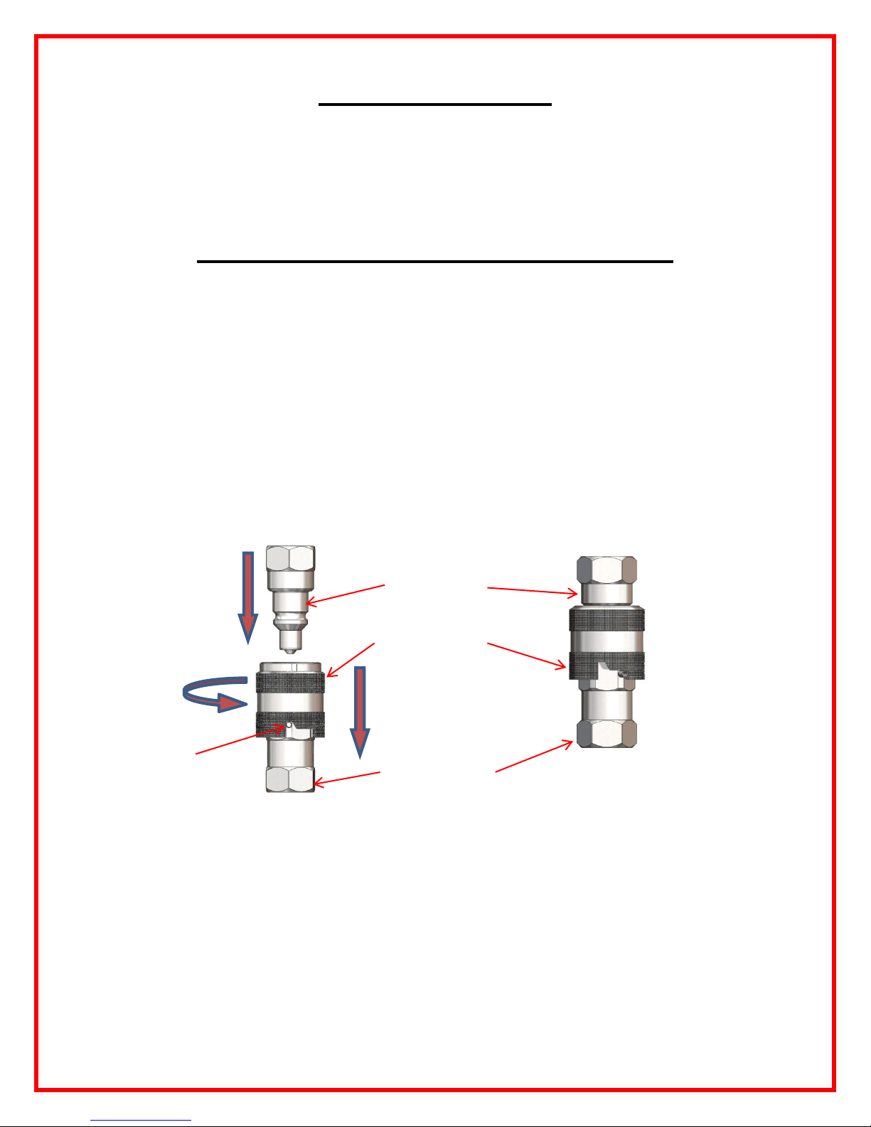
Standard 10,500 PSI Coupler Operation
1) Rotate locking collar counter clockwise until it lines up with pin and pull
back to the open position.(See Fig. 1)
2) Insert the male coupler into the female coupler and release the locking
collar to the locked position. (See Fig. 2)
3) Pull on couplers to confirm a completed connection.
4) To release, rotate locking collar clockwise to line up with pin and pull back
to release the male coupler.
Open Position Locked Position
Insert Male Coupler
Locking Collar
Pull Back
Rotate
Pin
Female Coupler
Fig. 1 Fig. 2
TNT-OM # 7.2.3-041 Rev: 03-14-2016 6/30
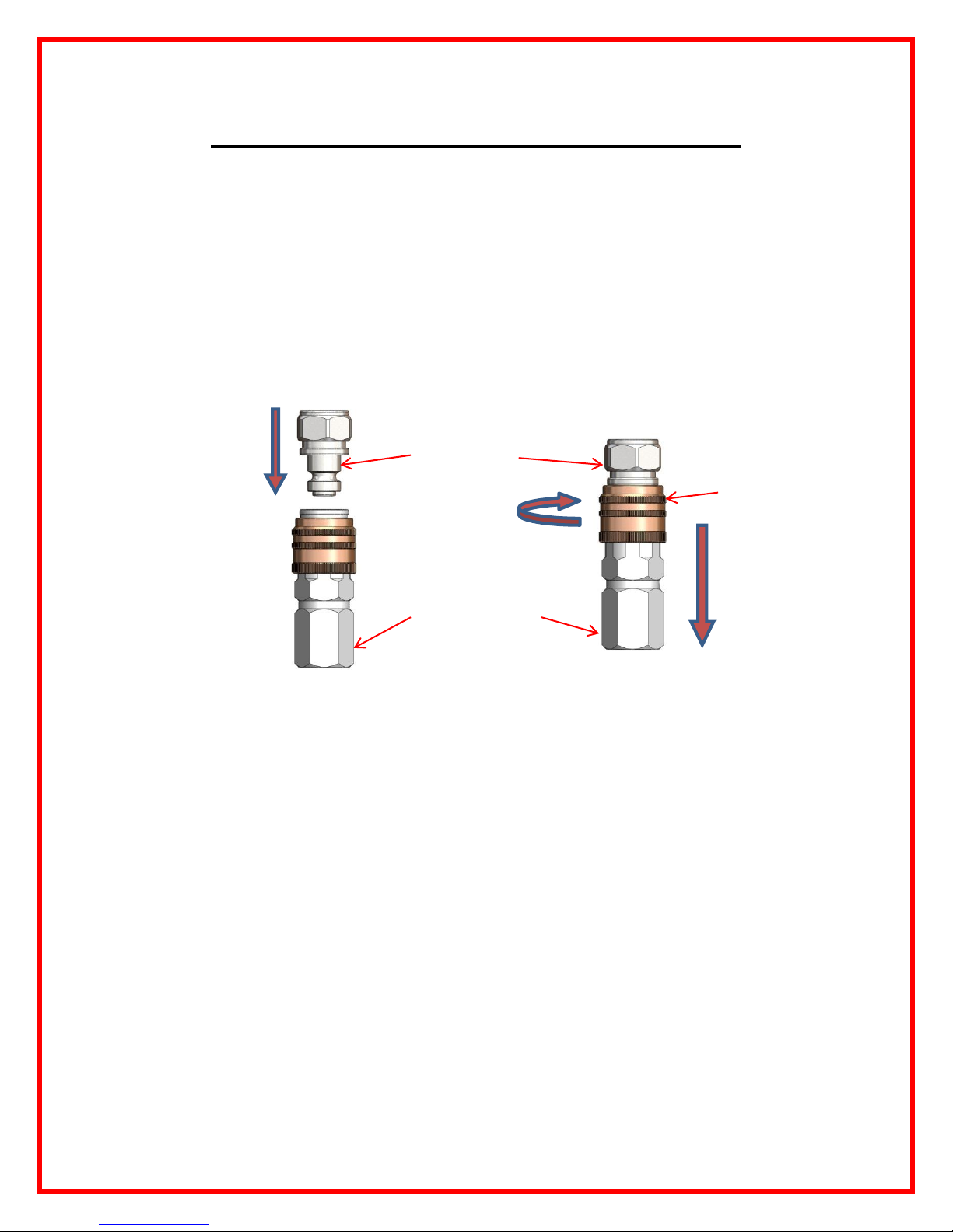
Flat Face 10,500 PSI Coupler Operation:
1) Insert the male coupler into the female coupler until it snaps in the locked
position.(See Fig. 1) and (Fig. 2)
2) Pull on couplers to confirm a completed connection.
3) To release, rotate locking collar clockwise until it stops and pull back to
release the male coupler. (See Fig. 2)
Open Position Locked Position
Insert
Male Coupler
Locking Collar
Rotate Pull Back
Female Coupler
Fig. 1 Fig. 2
TNT-OM # 7.2.3-041 Rev: 03-14-2016 7/30
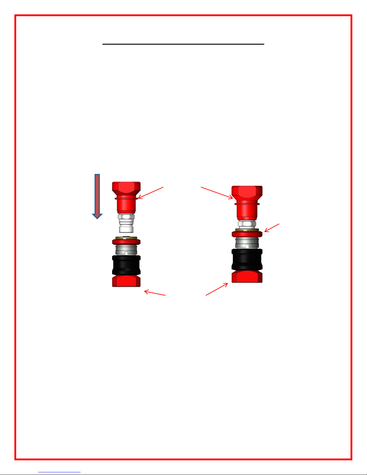
COAX 10,500 PSI Coupler Operation:
1) Insert the male coupler into the female coupler until it snaps in to the
locked position. (See Fig. 1 ) and ( Fig. 2 )
2) Pull on couplers to confirm a completed connection.
3) Pull back on the leverage collar to release the male coupler. (See Fig. 1)
Open Position Locked Position
INSERT Male Coupler
Leverage Collar
Female Coupler
Fig. 1 Fig. 2
TNT-OM # 7.2.3-041 Rev: 03-14-2016 8/30
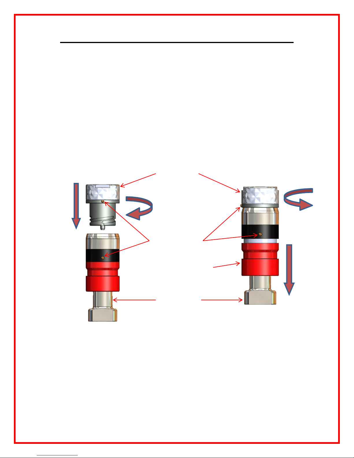
Nexus 5,500 and 10,500 PSI Coupler Operation:
1) Line up the alignment screws. (See Fig. 1)
2) Insert the male coupler into the female coupler and rotate clockwise until it
snaps into the locked position. (See Fig. 2)
3) Pull on couplers to confirm a completed connection.
4) To release, pull back the Locking collar and rotate the male coupler counter
clockwise and remove from female coupler, release collar.(See Fig. 2)
Open Position Locked Position
Male Coupler
Rotate
Insert
Rotate
Alignment Screws
Locking Collar Pull
Back
Female coupler
Fig. 1 Fig. 2
TNT-OM # 7.2.3-041 Rev: 03-14-2016 9/30
 Loading...