

Page 1
193-FX-(ST/SC) 100BASE TX/FX Converter Quick Start Guide
Thank you for purchasing our product. This quick start guide contains information
necessary to install and operate the 193-FX-(ST/SC) EtherFast 100BASE-TX/FX
converter. This guide is designed for experienced network installer.
Package Contents
Your package includes the following:
One EtherFast 100BASE-TX/FX converter
One AC power adapter
The quick start guide
Product Overview
The 193-FX-(ST/SC) EtherFast 100BASE-TX to 100BASE-FX converter is primarily
designed for larger and higher bandwidth demanding workgroups that require
expansion of the Fast Ethernet network. 193-FX-(ST/SC) features a RJ45 jack and an
ST or SC fiber optic connectors, connecting the 100BASE-TX network to the
100BASE-FX (fiber optic) network. The DIP switch on 193-FX-(ST/SC) provides the
option of operating in either full or half duplex modes. At full duplex mode, the
converter can create potential distances of up to 2 kilometers between a LAN switch and
another switch or a file server.
www.trinetusa.com
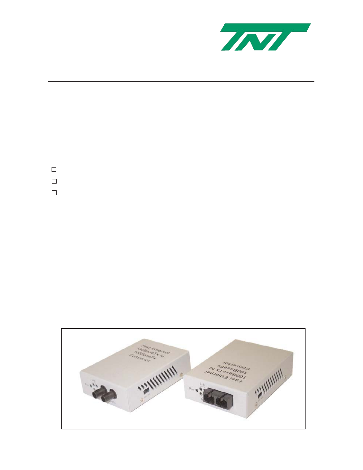
193-FX-ST
193-FX-SC
Page 2

Key Features
• Complies with IEEE802.3u 100BASE-TX and 100BASE-FX standard
• Provides one 100BASE-TX and one 100BASE-FX port
• Support ST or SC fiber connector
• Provides a slide switch to set the Half/Full duplex mode, for connection
between a full duplex device and a half duplex device
• Five LED indicator, Power, TX Link, TX Receive, FX Link and FX Receive
•
Extend fiber distance up to 2 Km when running in Full Duplex mode, Switch to
Switch connection, or Switch to Node connection
• Extend fiber distance up to 412 meter when running in Half Duplex mode, Switch to
• Switch connection, or Switch to Node connection
•
Extend fiber distance up to 208 meter when running in Half Duplex mode, Switch to
Hub connection, or Hub to Node connection
• External power adapter with 5V, 1.5A
• FCC Class A and CE approved
•
Wall Mountable
Applications
In order to achieve the purpose of effectively expanding the distance of the Fast
Ethernet network, position two 193-FXC (or 193-FXD) back to back between the
following devices:
Example A: Two LAN switches
Switch ----- 193-FX ------------------------ 193-FX ---- Switch
Example B: One LAN Switch and a LAN server
Switch ----- 193-FX ------------------------ 193-FX ---- Server
Example C: 100BASE-TX Hub and workstations (W/S)
Hub -------- 193-FX ------------------------- 193-FX ---- W/S
Instead of using tow 193-FX-(ST/SC) for "back to back" arrangement, another effective
application is to position one 193-FX directly between the 100BASE-TX network and
the Fiber-Optic (100BASE-FX) device.
Example D: Fiber Optic device and 100BASE-TX network
Fiber Optic Device --- 193-FX -------- 193-FX ---- 100BASE-TX network
Page 3

Installation
1.0 Connect the RJ45 port of 193-FX-(ST/SC) to the 100BASE-TX network.
1.1 The RJ45 port on 193-FX-(ST/SC) is an MDI-X port. Therefore, please use a
CAT 5 twisted-pair straight through cable to link with the MDI port of the hub or
switch, or use a CAT 5 twisted-pair cross-over cable to link with a MDI-X port of
the hub, switch, or the Fast Ethernet card in the Workstation.
1.2 Make sure that the length of the twisted-pair cable is as short as possible, so that
the fiber-optic cable can reach its maximum length.
1.3 Schematic of both straight and crossover twisted-pair cable are shown below.
Straight-Through Crossover
(Hub) (Adapter) (Hub) (Hub)
1 IRD+ 1 OTD+ 1 IRD+ 1 IRD+
2 IRD- 2 OTD- 2 IRD- 2 IRD3 OTD+ 3 IRD+ 3 OTD+ 3 OTD+
6 OTD- 6 IRD- 6 OTD- 6 OTD-
2.0 Connect the fiber-optic port of 193-FX-(ST/SC) to another 193-FX-(ST/SC) or the
100BASE-FX device.
2.1 Connect one (ST or SC) end of a fiber optic cable to the ST or SC connector on
the 193-FX-(ST/SC) and the other end of the fiber-optic cable to the ST or SC
connector on the other 193-FX-(ST/SC) or 100BASE-FX device.
DIP Switch
1. When the DIP switch is set to FDX, the RJ45 port of the 193-FX-(ST/SC)
converter is set at Full-Duplex mode. When the DIP switch is set to HDX, the
RJ45 port of the 193-FX-(ST/SC) converter is set at Half-Duplex mode
2. Set the DIP switch to FDX (full-duplex) only when the both ends of the
193-FX-(ST/SC) runs at full-duplex modes
Page 4
LED Indicators
The converter 193-FX-(ST/SC) provides LED indicators for monitoring various network
conditions. A glance at the LED displays allows you to instantly monitor the status of
each station port plus the overall condition of the converter.
LED Status
PWR (Power LED) Power LED, steady lit when the converter is power on.
LNK (TX and FX) Steadily lit when receiving link pulses from a compliant device.
RVC (TX and FX) Flashing or illuminated when data packets are being received.
Specifications
Model 193-FX-ST 193-FX-SC
Standard IEEE802.3u 100BASE-TX and 100BASE-FX
Connector
One RJ45 and one ST connector One RJ45 & one SC connector
Max. Distance Twisted Pair 100 meter (330 ft); Fiber Optic 2000 meter (6600ft)
Power Required AC adapter, 5V, 1.5A
Dimensions 110 mm x 68 mm x 23 mm
Temperature Operating: 0 to 50 degree C; storage: -40 to 70 degree C
Humidity Operating: 10% to 80%; Storage: 5% to 90%
Emission FCC Part 15 of Class A; CE
The product specification is subject to change without prior notice
www.trinetusa.com
The product specification is subject to change without notice. TNT is registered trademark of
Tri-Net Technologies, Inc. All other brands are owned by their respective companies.
 Loading...