

TMT TI-5700 Operation Manual

TI-5700
WEIGHING INDICATOR
OPERATION MANUAL
VER 101
DIGITAL WEIGHING INDICATOR TI-5700
This is warning & caution mark
This is hazard alert mark
This is useful information mark
NOTE
(1) The unauthorized copying of some or all of this manual is prohibited.
(2) The information contained herein is subject to change without notice.
(3) If there are any questions such as wrong or missing parts of the
contents listed in this manual, please contact us.
(4) To improve the product performance, functions can be changed with
no notice.
(5) Please understand that TMT does not have responsibility for a
demand related to loss, lost profit etc. caused by operating the
product, regardless of the third clause.
WARNING DEFINITIONS
- 2 -

DIGITAL WEIGHING INDICATOR TI-5700
INDEX
1. Precautions ..................................................................................................... 4
2. Introduction ................................................................................................... 5
3. Description of Panels and Symbols .................................................... 6
4. Installation ...................................................................................................... 8
5. Calibration ....................................................................................................12
6. Setting Mode ..............................................................................................18
7. General Function for Weighing Mode .............................................32
8. Weighing check & batching mode ...................................................36
9. Test Mode .....................................................................................................44
10. Solid State Relay and Control Inputs (OP-01) ...........................46
11. RS-232C Interface (OP-02) ..................................................................47
12. RS-422/485 Interface (OP-03) ...........................................................51
13. Analog Output (OP-04) ........................................................................52
14. Current Loop Output (OP-05) ...........................................................53
15. LAN IEEE 802.3 (OP-06) .......................................................................53
16. BCD Output (OP-07) ..............................................................................54
17. USB Host (OP-08) ...................................................................................56
18. ZigBee Wireless (OP-09) ......................................................................58
19. Bluetooth Wireless (OP-10) ................................................................59
20. Rechargeable Li-Po Battery (OP-11) ..............................................60
21. Specifications ............................................................................................61
22. Check Message ........................................................................................62
- 3 -
DIGITAL WEIGHING INDICATOR TI-5700
1. Precautions
Please be informed that we‟re not responsible for any incident or mishap caused
by partial modification of this product. To avoid such situation, customers need to
contact our customer service team or system installation staff in advance, and any
modification should be conducted under our surveillance.
Do not install the indicator in strong direct sunlight and dust.
Please confirm that the local voltage is correct for the indicator.
Do not use inflammable substances for cleaning.
Do not use the product in the rain. Keep it dry.
Avoid sudden changes of temperature if possible
Do not use the product in a place with a high-voltage current or severe
electronic noise.
Do not use the product in a place with severe vibration.
Do not put too much pressure to keys.
- 4 -
DIGITAL WEIGHING INDICATOR TI-5700
2. Introduction
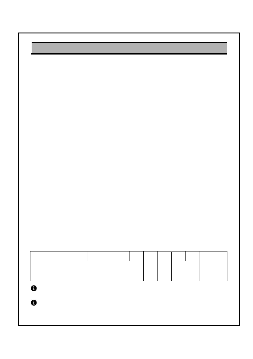
OPTION
01
02
03
04
05
06
07
08
09
10
11
12
CASE 1
○
Select one of them
X
○
Select one
of them
○ ○ CASE 2
X
○ ○ ○
○
◆ The TI-5700 is a compact simple batch weighing indicator
◆ Standard functions are as below
◊ Main display of 6 digit FSTN LCD and LED backlight
◊ 3-stage limit comparison to check a mass value
◊ 8 item code comparison for batching applications
◊ The accumulation to weight data and count
◊ The average or peak hold functions
◊ The zero and tare functions
◆ Optional functions are as below
◊ OP-01: 3 solid state relay and inputs
◊ OP-02: RS-232C serial interface
◊ OP-03: RS422 / 485 serial interface.
◊ OP-04: 4~20mA / 0~10V analog output
◊ OP-05: Current loop output
◊ OP-06: LAN IEEE 802.3
◊ OP-07: BCD output
◊ OP-08: USB host
◊ OP-09: ZigBee wireless
◊ OP-10: Bluetooth wireless
◊ OP-11: Rechargeable Li-Po battery
◊ OP-12: Stainless steel mount bracket
◆ Selection criteria for optional functions
X: Can‟t be selected with option.
(e.g., OP-07 can repeatedly select OP-08/11/12 and select one of OP-09/10)
OP-08 to 10 are must be selected before ordering.
- 5 -
DIGITAL WEIGHING INDICATOR TI-5700
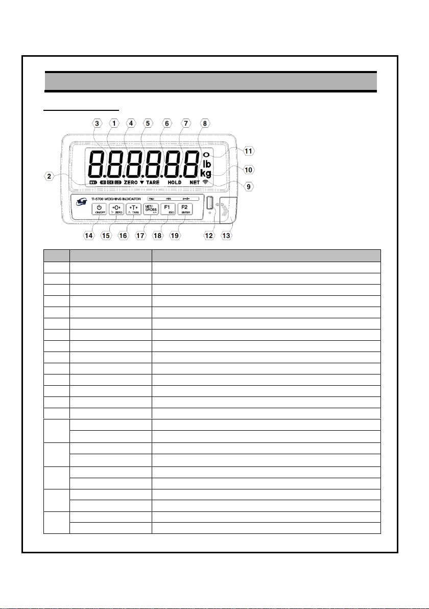
3. Description of Panels and Symbols
No.
Name
Description
1
Display
Display the weight data & message
2
Battery
Indicates when a battery has to be recharged
3
HI/OK/LO
Indicates the results of comparison
4
Zero
Indicates when the weight is zero
5
Accumulation
Indicates when there is accumulation weigh.
6
Tare
Indicates when the tare is included
7
Hold
Indicates when the hold function is set
8
Net
Indicates when the weight is the net weight
9
Wireless
Indicates when the wireless communicates data
10
Unit
Unit used to weigh
11
Stable
Indicates when the weight is stable
12
USB
USB host port for memory stick
13
CAL cover
CAL switch cover (For calibration)
14
ON/OFF key
Power ON/OFF of indicator
15
ZERO key
The key to make weight value as zero
> key
The key to move a digit of one in the set & calibration mode
16
TARE key
The key to perform tare weight
∧ key
The key to add a value of one in the set & calibration mode
17
NET/GROSS key
The key to select net or gross weight
+/- key
The key to select plus or minus of a value
18
F1 key
This key can be selected by operator in the set mode
ESC key
The key to escape from the present mode
19
F2 key
This key can be selected by operator in the set mode
ENTER key
The key to store/confirm setting value
3.1. Front panel
- 6 -

No.
Name
Description
1
Battery cover
Lithium polymer battery compartment cover
2
Panel bracket
Standard panel bracket
3
Option panel cover
For OP-01, 02, 03, 04, 05, 06 and 07
4
Load cell connector
Connect the load cell
5
Ground terminal
Frame ground (F.G.)
6
DC jack
Uses the supplied adaptor (12VDC 1A )
3.2. Rear panel
DIGITAL WEIGHING INDICATOR TI-5700
The F.G. terminal must be grounded to avoid electric shock and interference
from static discharge.
- 7 -
DIGITAL WEIGHING INDICATOR TI-5700
4. Installation
4.1. Power supply
Use only approved power adaptor and batteries.
Do not connect incompatible products.
Use only batteries, chargers, adaptor, and enhancements approved by TMT for
use with this particular model.
The use of any other types may invalidate any approval or warranty, and may be
dangerous. For availability of approved enhancements, please check with your
dealer.
When the standard AC adapter is used
◊ Check the power supply voltage
◊ Must be uses the supplied AC adaptor.
◊ A stable power source must be used;
An unstable power source may result in a malfunction.
◊ Connect the DC jack to rear side of the indicator.
When the Li-Po battery pack is used
◊ Refer to “21. Rechargeable Li-Po Battery (OP-11)”
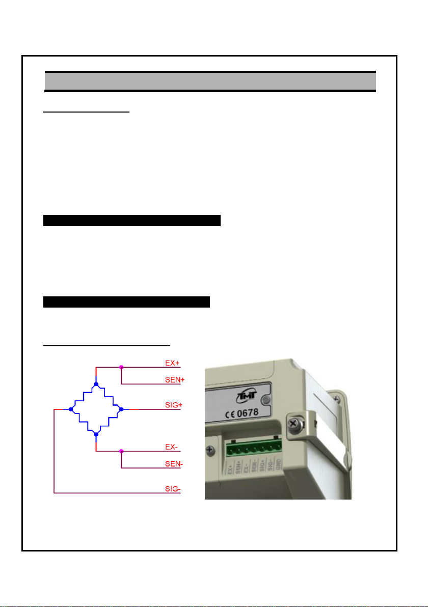
4.2. Load cell connections
- 8 -
DIGITAL WEIGHING INDICATOR TI-5700
Connect the load cell wire to the connector, at the rear panel
◊ Load cell wire color depends on the manufacturer of load cell, please check the
load cell specification.
◊ It is possible to connect a 4 wire cable provided that pins EX+/SEN+ and pins
EX-/SEN- are shorted.
◊ It is possible to connect eight (8) 350 ohm load cells.
◊ If you connect other wires to load cell terminal wrongly, it may cause
damage in the indicator circuit.
Before connecting the load cell wire, you must power off and be sure to connect
the load cell wire to the terminal correctly.
◊ The output voltage of a load cell is a very sensitive signal.
Don‟t weld near the load cell & indicator. Also, place the load cell cable away
from any noise source.
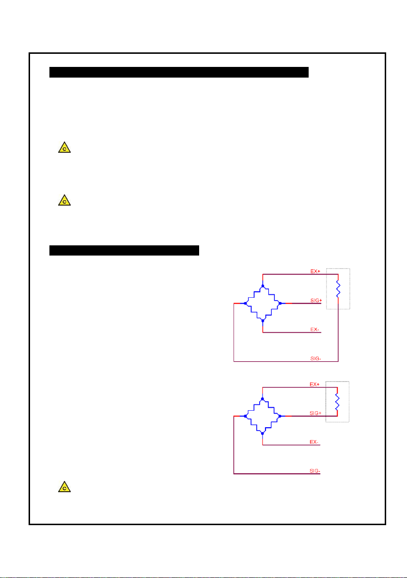
Adjustment of the load cell output
◊ In case of reducing the output.
When the zero output is too large,
add a resistor between EX+ and SIG-.
This should shift the zero point to negative.
◊ In case of increasing the output.
When the zero output is too small,
add a resistor between EX+ and SIG+.
This should shift the zero point to positive.
◊ Use a metal film resistor in the range of 50kohm to 500kohm with a good
temperature coefficient. (Below 1%)
- 9 -
DIGITAL WEIGHING INDICATOR TI-5700
EV: Excitation voltage [mV]
RO: Rated output [mV/V]
e: Weighing interval [kg]
LC: Rated capacity of load cell [kg]
N: Number of load cells
EV × RO × e
0.2 ≤
LC × N
(Input sensitivity is 0.2uV/D)
EXAMPLE
Load cell: N=1
Rated capacity: LC=1,000kg
Rated output: RO=2mV/V
Excitation voltage: EC=5000mV
Weighing interval: e=0.02kg
5000 × 2 × 0.02
0.2 =
1000 × 1
Regard the instrument as a good design
Verifying load cell output and input sensitivity
Adapt to the following inequality, when you design a weighing instrument using the
indicator and load cells.
- 10 -
DIGITAL WEIGHING INDICATOR TI-5700
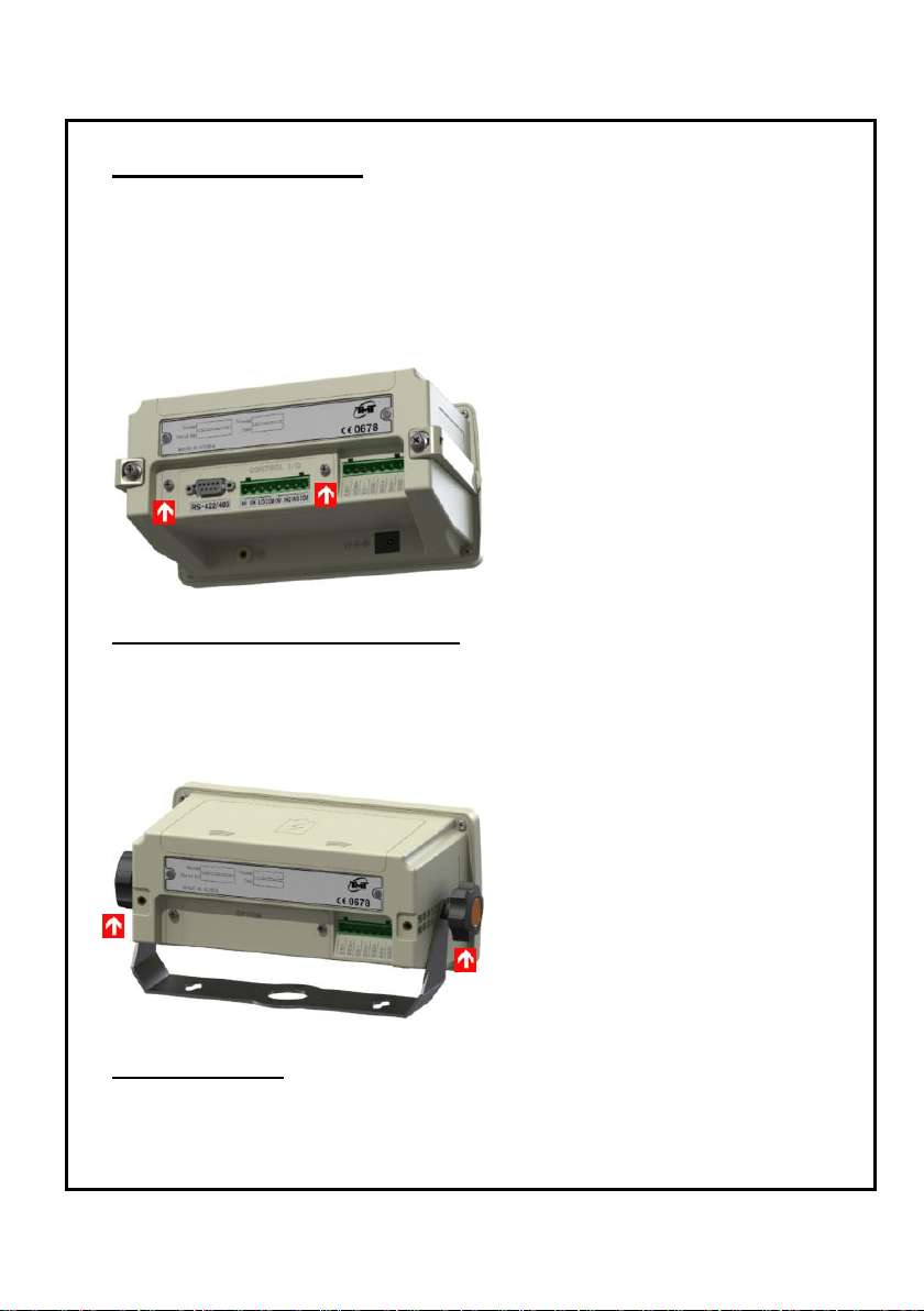
4.3. Option board install
This is the procedure for the OP-01 to OP-07 option board.
Step 1. After power off, remove the AC adapter or batteries.
Step 2. As shown in the figure below, remove the two screws and the blank panel.
Step 3. Align the option board with guides inside of option part and Insert the
option board to the connector of main board.
Step 4. Tighten the screws of option board.
4.4. Mount bracket install (OP-12)
Step 1. After power off, remove the AC adapter or batteries.
Step 2. Remove the panel guide bracket.
Step 3. As shown in the figure below, secure the mount bracket to both sides with
the bolts provided.
4.5. Accessories
◊ Operation manual ◊ AC adaptor (12VDC 1A) ◊ Load cell plug (7pin)
- 11 -
DIGITAL WEIGHING INDICATOR TI-5700
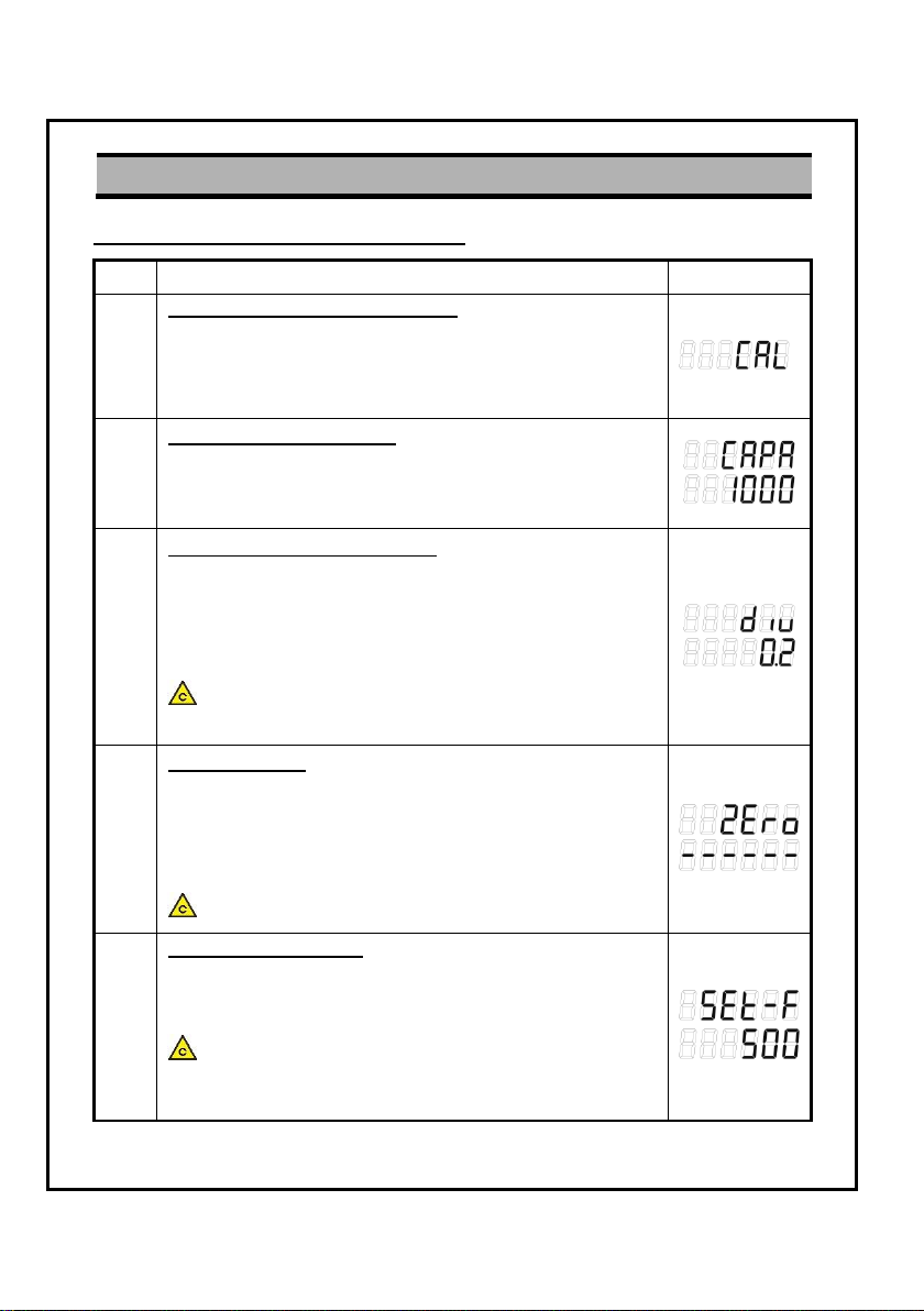
5. Calibration
Step
Operation & Description
Display
1
How to enter the calibration mode:
Press the CAL key which is located behind the CAL cover at
the front panel of indicator.
When “CAL” is displays, press the F2 key.
Then this calibration mode is stared.
2
Setting maximum capacity:
After “CAPA” is displayed, input the max. capacity with keys.
(>: increase the digit, ∧: increase the value)
Press ENTER key to save and move to next step.
3
Setting minimum scale division:
After “DIV” is displayed, select min. scale division with keys.
(>: increase the value, ∧: decrease the value)
Press ENTER key to save and move to next step.
If you press the ESC key, it turns back to weighing mode after
save maximum capacity & minimum scale division.
The display resolution is cannot be over than 50,000.
(Display resolution = Max. capacity / Min. scale division)
4
Zero calibration:
Place nothing on the weighing unit.
When “ZERO” is displayed, press the ENTER key after the
Stable mark has turned on.
If you press the ESC key, it turns back to weighing mode after
execute zero calibration.
Do not press the keys while the stable mark is off.
5
Input a balance weight:
After “SET-F” is displayed, input a balance weight with keys.
(>: increase the digit, ∧: increase the value)
Press ENTER key to save and move to next step.
It is recommendable to calibrate using a balance weight
which weights 10% of the maximum capacity or more in terms
of linearity.
5.1. Calibration by a balance weight
- 12 -

DIGITAL WEIGHING INDICATOR TI-5700
6
Span calibration:
Place balance weight on the weighing unit.
When “LOAD” is displayed, press the ENTER key after the
Stable mark has turned on.
Do not press the keys while the stable mark is off.
7
Fine adjustment:
After span calibration, balance weight is shown on the display.
Confirm if the displayed weight is equal to the balance weight
that you have set in step 5.
The bias is "0" when the OK lamp lights up.
If HI or LO lamp is on, you can be adjusted to the keys.
(>: increase the 0.1digit, ∧: decrease the 0.1digit)
After fine adjustment, remove the weight from the weighing
unit. If "0" is displayed, press the ENTER key.
8
Complete:
After confirm if the weighing units is empty, press the ENTER
key then you will go to normal mode.
- 13 -
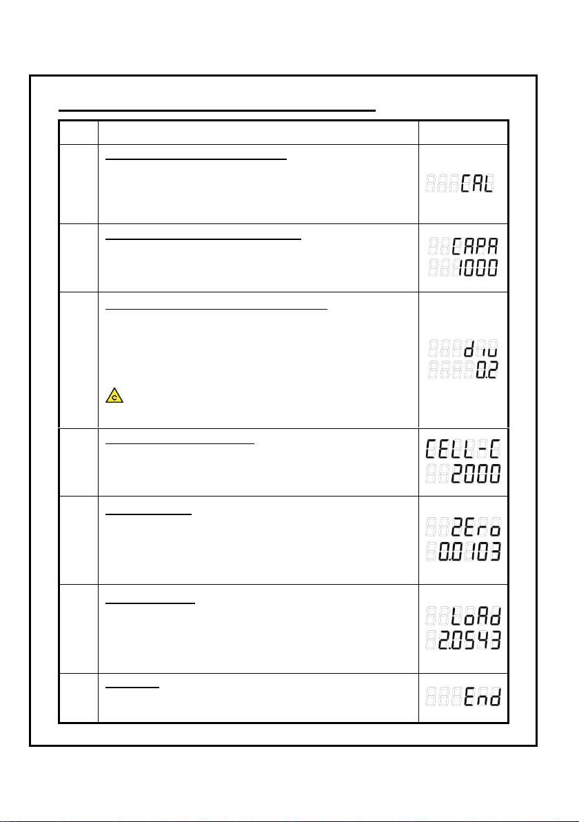
DIGITAL WEIGHING INDICATOR TI-5700
Step
Operation & Description
Display
1
How to enter the calibration mode:
Press the CAL key which is located behind the CAL cover at
the front panel of indicator.
When “CAL” is displays, press the F1 key.
Then this calibration mode is stared.
2
Setting maximum capacity of a scale:
After “CAPA” is displayed, input the max. capacity with keys.
(>: increase the digit, ∧: increase the value)
Press ENTER key to save and move to next step.
3
Setting minimum scale division of a scale:
After “DIV” is displayed, select min. scale division with keys.
(>: increase the value, ∧: decrease the value)
Press ENTER key to save and move to next step.
If you press the ESC key, it turns back to weighing mode after
save maximum capacity & minimum scale division.
The display resolution is cannot be over than 50,000.
(Display resolution = Max. capacity / Min. scale division)
4
Setting capacity of load cell:
After “CELL-C” is displayed, input maximum capacity of load
cell with keys. (>: increase the digit, ∧: increase the value)
Press ENTER key to save and move to next step.
5
Zero calibration:
After “ZERO” is displayed, input voltage parameter of the zero
points is displayed in the unit of mV/V with keys.
(>: increase the digit, ∧: increase the value)
Press ENTER key to save and move to next step.
6
Span calibration:
After “LOAD” is displayed, input voltage parameter of the span
points is displayed in the unit of mV/V with keys.
(>: increase the digit, ∧: increase the value)
Press ENTER key to save and move to next step.
7
Complete:
After confirm if the weighing units is empty, press the ENTER
key then you will go to normal mode.
5.2. Calibration by voltage parameter of load cell
- 14 -
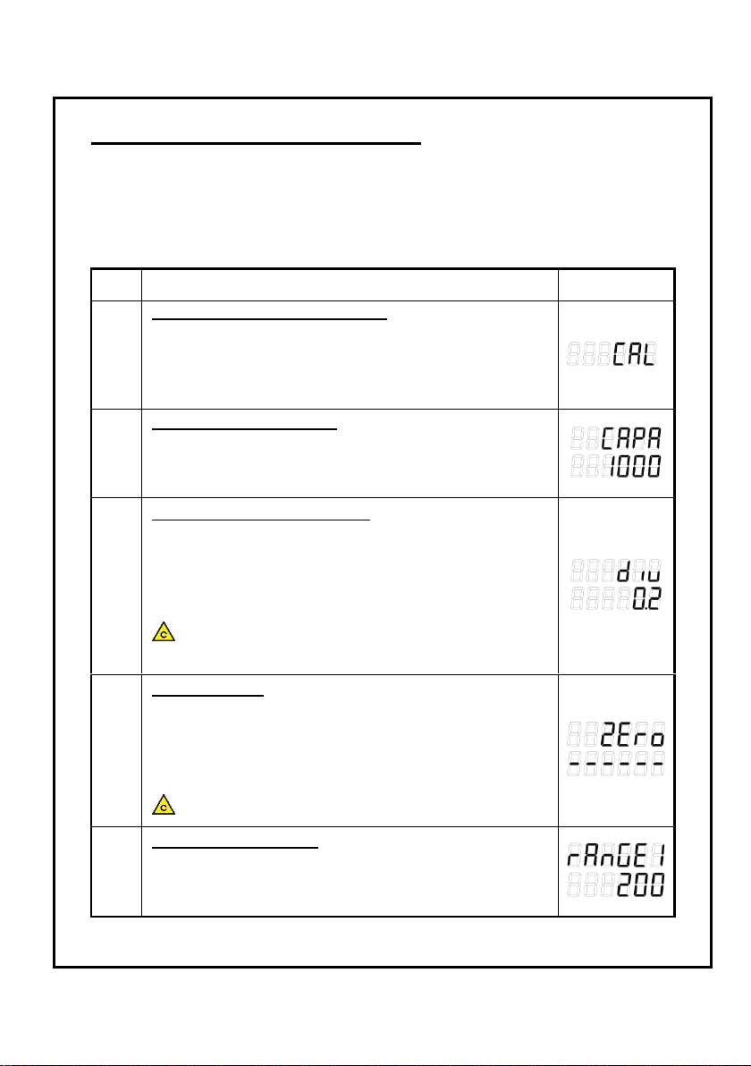
DIGITAL WEIGHING INDICATOR TI-5700
Step
Operation & Description
Display
1
How to enter the calibration mode:
Press the CAL key which is located behind the CAL cover at
the front panel of indicator.
When “CAL” is displays, press the NET/GROSS key.
Then this calibration mode is stared.
2
Setting maximum capacity:
After “CAPA” is displayed, input the max. capacity with keys.
(>: increase the digit, ∧: increase the value)
Press ENTER key to save and move to next step.
3
Setting minimum scale division:
After “DIV” is displayed, select min. scale division with keys.
(>: increase the value, ∧: decrease the value)
Press ENTER key to save and move to next step.
If you press the ESC key, it turns back to weighing mode after
save maximum capacity & minimum scale division.
The display resolution is cannot be over than 50,000.
(Display resolution = Max. capacity / Min. scale division)
4
Zero calibration:
Place nothing on the weighing unit.
When “ZERO” is displayed, press the ENTER key after the
Stable mark has turned on.
If you press the ESC key, it turns back to weighing mode after
execute zero calibration.
Do not press the keys while the stable mark is off.
5
Input 1st balance weight:
After “RANGE1” is displayed, input 1st balance weight with
keys. (>: increase the digit, ∧: increase the value)
Press ENTER key to save and move to next step.
5.3. Multi calibration (5 weighing point)
Even if the single calibration has been completed, there may still remain a linearity
deviation caused by the performance of the weighing unit.
The multi calibration can rectify or reduce the linearity deviation using weighing
points during the zero and capacity setting.
Up to five weighing points can be specified.
- 15 -
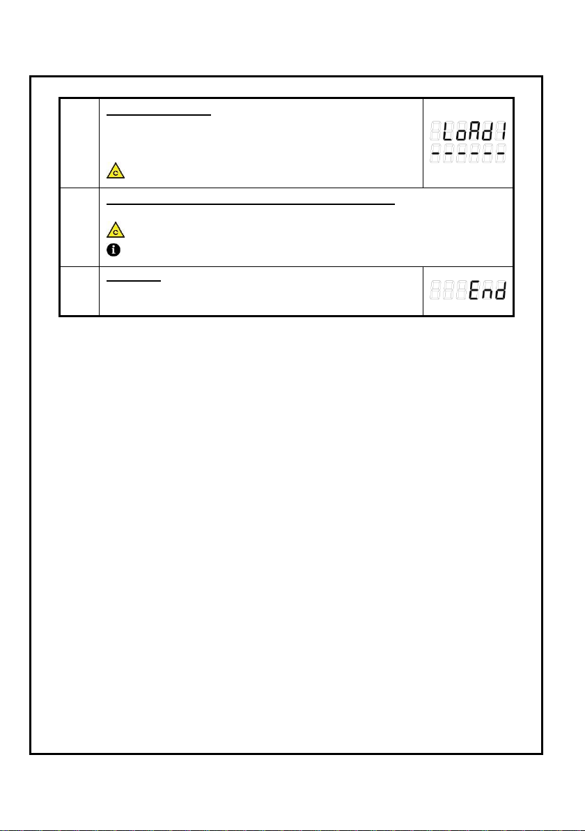
DIGITAL WEIGHING INDICATOR TI-5700
6
1st span calibration:
Place 1st balance weight on the weighing unit.
When “LOAD1” is displayed, press the ENTER key after the
Stable mark has turned on.
Do not press the keys while the stable mark is off.
7
2nd, 3rd, 4th, 5th input balance weight & span calibration:
Repeat steps 5, 6, 7 for each.
5
th
set value must be the maximum capacity.
If you want reduce to 2 weighing point, set to be equal 2
nd~5th
balance weight.
8
Complete:
After confirm if the weighing units is empty, press the ENTER
key then you will go to normal mode.
- 16 -

DIGITAL WEIGHING INDICATOR TI-5700
Step
Operation & Description
Display
1
How to enter the calibration mode:
Press the CAL key which is located behind the CAL cover at
the front panel of indicator.
When “CAL” is displays, press the TARE key.
Then this gravity compensation mode is stared.
2
Setting gravity acceleration of calibration location:
After “GSET-1” is displayed, input gravity acceleration of
calibration location with keys.
(>: increase the digit, ∧: increase the value)
Press ENTER key to save and move to next step.
(9.799m/s2)
3
Setting gravity acceleration of using location:
After “GSET-2” is displayed, input gravity acceleration of using
location with keys.
(>: increase the digit, ∧: increase the value)
Press ENTER key to save and move to next step.
(9.788m/s2)
4
Complete:
After confirm if the weighing units is empty, press the ENTER
key then you will go to normal mode.
5.4. Gravity compensation
This function allows it to be calibrated in one location and then adjusted to
match the acceleration of gravity at another location where it will be used.
If the GSET-1 value is same with GSET-2, it doesn‟t need to do gravity
compensation set.
- 17 -
DIGITAL WEIGHING INDICATOR TI-5700
6. Setting Mode
Value
Description
00
256Hz
If a higher parameter is set, the display speed will be
slow, but response will be more insensitive to
environment such as vibration.
In contrast, If a lower parameter is set, the display
speed will be fast, but response will be more sensitive to
environment such as vibration.
01
128Hz
02
64Hz
03
32Hz
04
16Hz
05
10Hz
06
8Hz
07
6Hz
08
4Hz
09
2Hz
6.1. How to enter
To enter the function settings, do either of the following.
A) When the display is off, press ON/OFF key while pressing the TARE key.
B) When in the weighing mode, press and hold the TARE key for more 2 seconds.
Step 1. At this time, “F-01” is shown on the display after “SET” message.
Step 2. You can select the menu that you want to set. Enter number of set menu
by pressing the arrow keys and then press ENTER key.
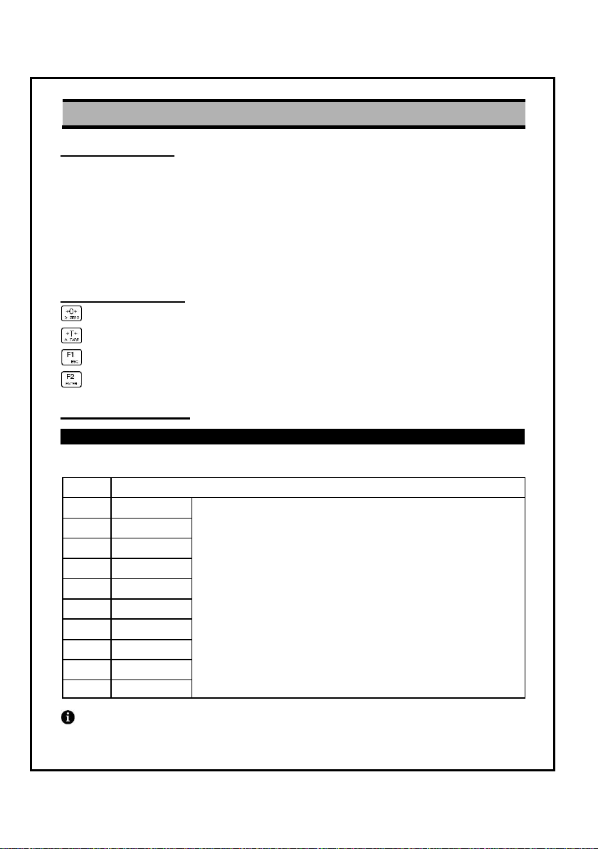
6.2. Available keys
: Used to move the input value to the left or right by one place.
: Used to increase the setting constant one by one.
: Used to escape from setting mode.
: Used to move next menu after completing input value.
6.3. Function menu
General function
◊ F01: A/D output data rate (0~9)
Bolded display is factory default set value.
- 18 -
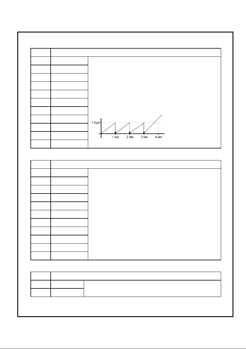
Value
Description
00
OFF
The zero tracking function will automatically bring the
display back to zero when there are small deviations.
For example: F02-02 setting.
As shown in the figure below, display will automatically
zero at less than 1digit per second.
01
0.5d/1sec.
02
1.0d/1sec.
03
1.5d/1sec.
04
2.0d/1sec.
05
2.5d/1sec.
06
0.5d/2sec.
07
1.0d/2sec.
08
1.5d/2sec.
09
2.0d/2sec.
10
2.5d/2sec.
Value
Description
00
OFF
Per each A/D conversion, the current weight is
compared to previous weight by this parameter.
If any of the set parameters are exceeded, stable
display goes off.
The ZERO key and TARE key are active in the stable
state. If these keys need to be active in the unstable
state, set to F03-00.
01
0.5d/0.5sec.
02
1.0d/0.5sec.
03
2.0d/0.5sec.
04
3.0d/0.5sec.
05
4.0d/0.5sec.
06
0.5d/1sec.
07
1.0d/1sec.
08
2.0d/1sec.
09
3.0d/1sec.
10
4.0d/1sec.
Value
Description
0
OFF
If this function is active, In case occurring sudden power
failure, it can be memory the moment value.
1
ON
◊ F02: Zero tracking (0~10)
◊ F03: Motion detection (0~10)
DIGITAL WEIGHING INDICATOR TI-5700
◊ F04: Weight backup (0,1)
- 19 -
DIGITAL WEIGHING INDICATOR TI-5700
Value
Description
0
Not used
1
When LO lamp is on
2
When OK lamp is on
3
When HI lamp is on
Value
Description
0
Manual ON/OFF
1
Automatic ON/OFF (Weighing: ON / Zero: OFF)
2
Always ON
Value
Description
0
10%
The brightness of the backlight is adjusted depending on
this parameter.
4
50%
9
100%
Value
Description
0
Kg
Use this function depending on unit of weights which is
used in calibration mode.
1 g 2
lb
Value
Description
0
OFF
Auto power OFF function is not used.
1
1minute
Weight is stable and not using for 1 or 5 minutes,
automatically power OFF.
2
5minutes
◊ F05: Buzzer beep (0~3)
buzzer beep time: 2times/sec.
◊ F06: Backlight conditions (0~2)
◊ F07: Backlight brightness level control (0~9)
◊ F08: Weighing unit change (0~2)
◊ F09: Auto power OFF function (0~2)
- 20 -
 Loading...