

Page 1
Unit 6, 476 Gardeners Rd, Alexandria, NSW 2015 Phone +612 8011 0500 Email info@tm-systems.com.au
Technical User Manual
The army knife for audio
Page 2

IMPRINT
Manual - Version 2.0
Print version 2
Edition 2
April 2018, Australia
Published as a digital PDF document
Publisher
tm stagetec systems
Unit 6 / 476 Gardeners Road Alexandria NSW 2015
Tel.: (02) 8188 0500
Fax: (02) 8072 1858
Email: [email protected]
Managing Director: Treva Head
General Manager: Mark Lownds
This document is subject to changes without prior notification.
All rights reserved.
Page 3

1. Introduction 2
2. Product Description 3
2.1 Analogue Audio 4
2.2 Digital Audio 5
2.3 Ethernet and Power 6
3. Setting up 7
3.1 What‘s in the box 7
3.2 Installing 7
3.3 Wiring 8
4. Device Setup 9
5. Technical Data 29
CONTENTS
1
Page 4

1. INTRODUCTION
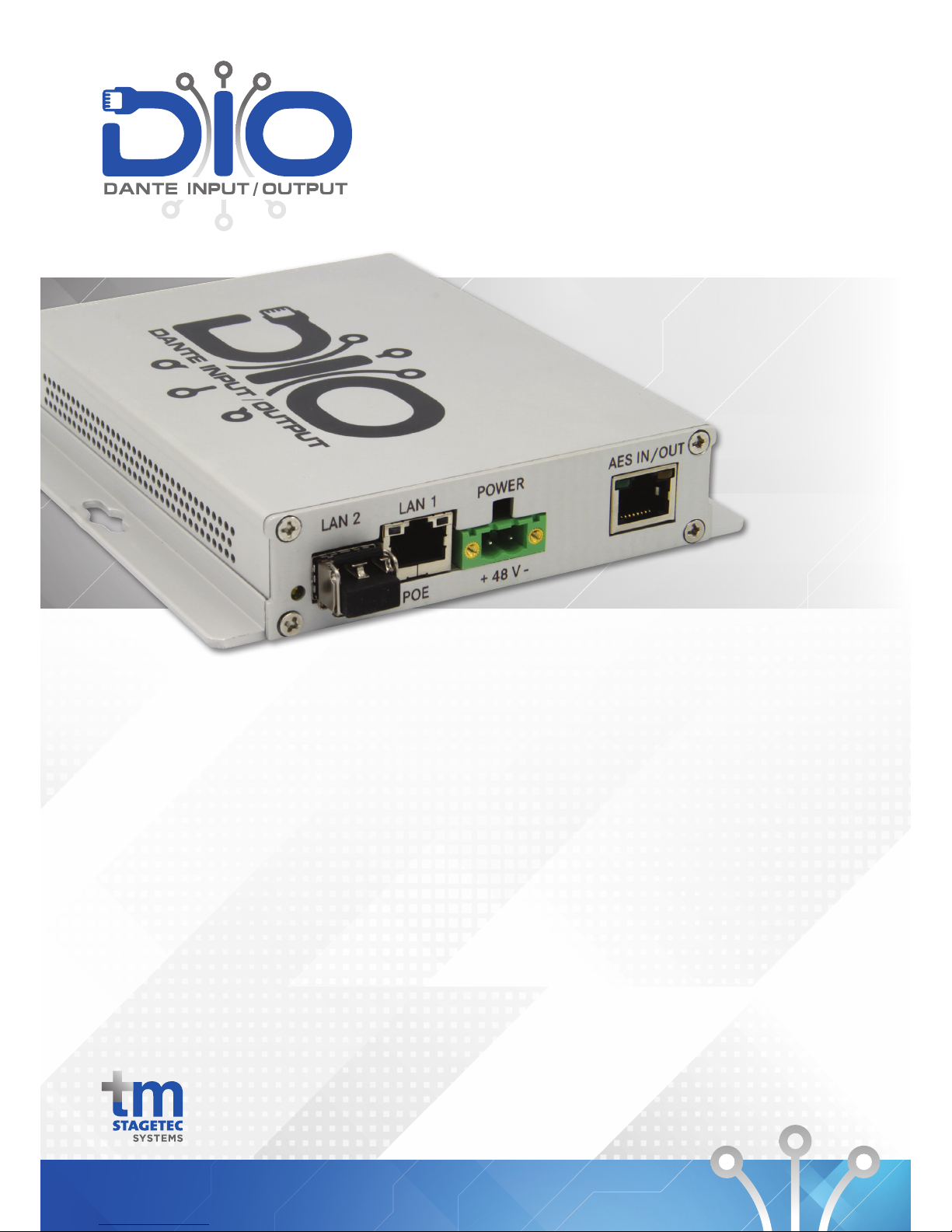
Thank you for choosing tm stagetec systems’s DIO device,
DIO stands for Dante ™ Input Output. We created the DIO
as the army knife for audio, with an impressive range of
tools and converters. It boasts a 2 port Ethernet switch (1x
1Gb Copper and 1x SFP cage - allowing for various fibre or
copper connections), Dante™ audio, AES Input and Output,
Mic Input, Line Input, Line Output, Headphone Output with
external volume control and 2 x GPIO. The DIO is powered
by PoE (Power over Ethernet) or runs via an external PSU.
Redundancy is provided between both power sources.
Please read this manual before attempting to operate your
new device to ensure reliable operation for years to come.
For any additional questions that are not addressed in this
document, feel free to contact tm stagetec systems directly.
2
Page 5
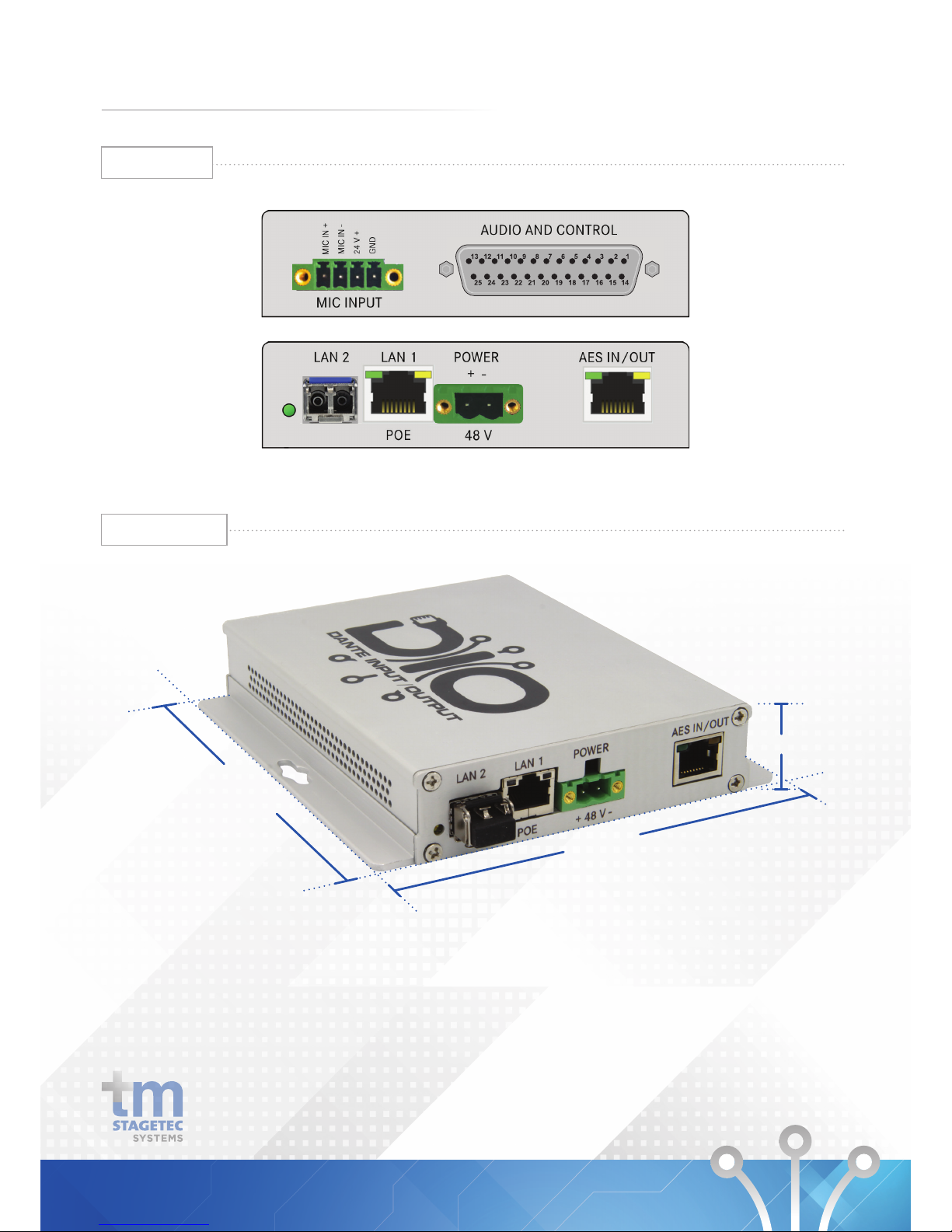
2. PRODUCT DESCRIPTION
145mm
130mm
27mm
Dimensions
Interfaces
3
Page 6
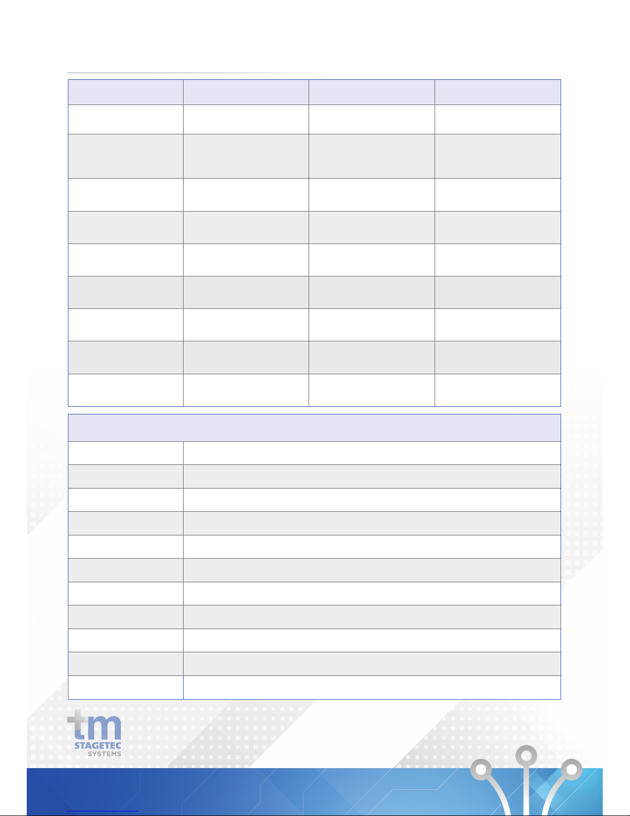
Balanced Inputs Balanced Outputs Headphone Amplifier
Connection Type D25 Connector 25 Connector D25 Connector
Channel
- 2 x Balanced,
- Max input level +24dBu
- 2 x Balanced,
- Max output level+24dBu
- 2 channel,
- 15vpp 220Ohm load
- 8vpp 50Ohm Load
- short circuit protected
Sample Rate 48kHz (24bit) 48kHz (24bit) N/A
Dynamic Range > 95dB (A weighted) > 97dB (A weighted) > 97dB (A weighted)
THD
- < -83dB 1kHz +18dBu input
- -6dBFs output
- < -86dB 1kHz -6dBFs
- 18dBu ouput
< -85dB 1kHz -6dBFs
Frequency Response 20Hz -20kHz 20Hz -20kHz 20Hz -20kHz
Channel Gain Control
+6dB to -12dB in 0.5db
increments
+20dB to -57dB in 0.5db
increments
N/A
Soft Clipper N/A N/A 0.1 to 10, in 0.1 increments
External Volume Control N/A N/A
Channel and gain range
selectable
Input (Microphone)
Connection Type Phoenix Connector
Input Gain Block Phoenix Connector
Dynamic Range > 95dB (A weighted) unity gain , -112 dBu EIN150ohm reference -50dBu input level
Frequency Response 20Hz - 20kHz
THD < -80dB 1khz 0dBu input , -3dBFs output
Attack TC 6ms to 2000ms
Release TC 24ms to 786430ms
Hold 2ms to 87491ms
Noise Gate Threshold 30 to -77db relFS
Phantom Power +48v selectable
External DC output +24v 40ma
2.1 ANALOGUE AUDIO
4
Page 7
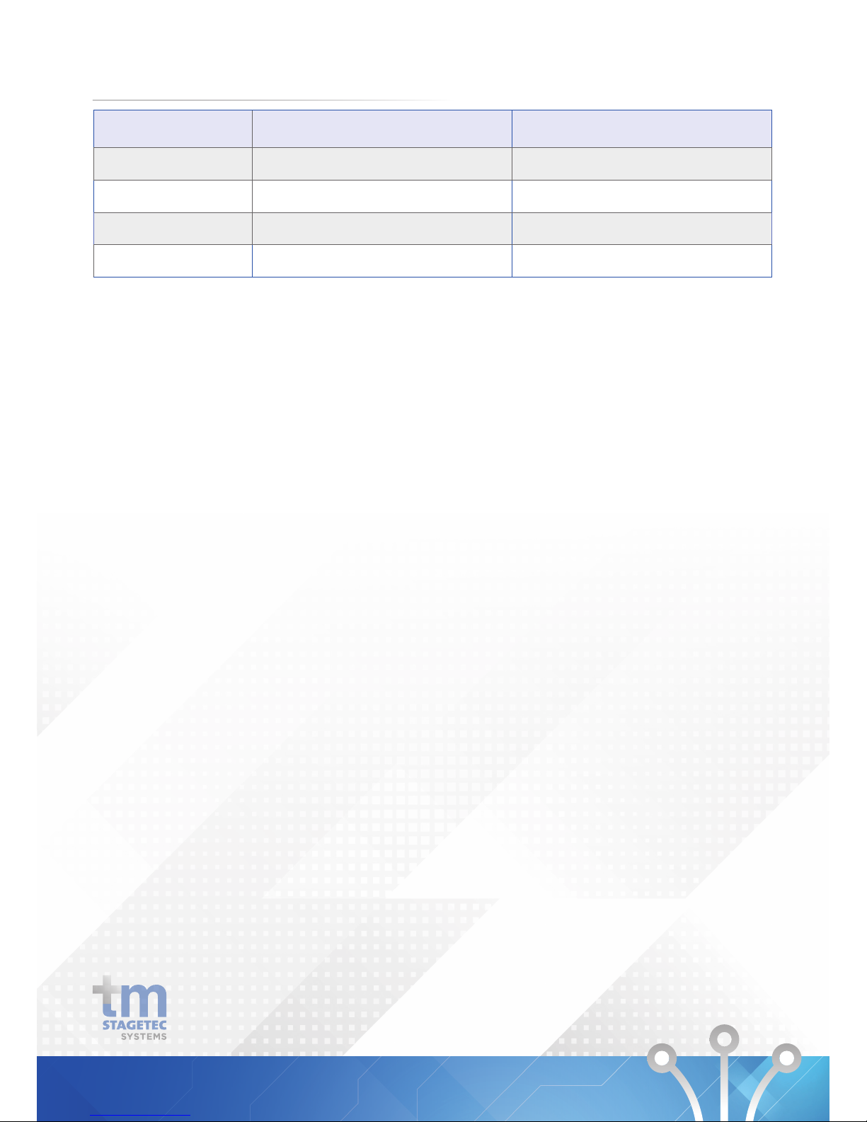
Input Output
Connection Type RJ45
RJ45
Sample Rate 48 kHz (32bit) 48 kHz (32bit)
Modes Transparent / Non Transparent N/A
Redundancy 2 x Buffered inputs (via Dante) N/A
Message Player (Option)
Wav, MP3 Message player triggered by GPIO or UDP protocol.
GPIO
Inputs 2 x Opto Inputs - Max 5mA Sink
Outputs 2 x Outputs, bis 200V, max. 150mA
2 x Isolated Outputs - 200V Max 150mA
2.2 DIGITAL AUDIO
5
Page 8
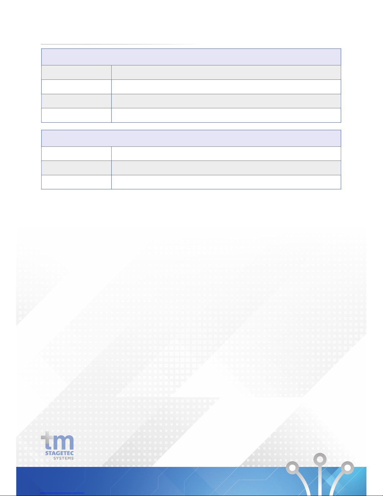
Ethernet
Switchports
2
Port 1 1 Gbit Copper (POE IN)
Port 2 1 G bit Copper or Fibre (SFP Cage)
DANTE™ Configuration 8 x 8
Power
External*
12-48 Volts
Power Over Ethernet * POE Switch benötigt / required
Power 10 Watt / Watts
*Redundancy power is provided between both inputs.
2.3 ETHERNET AND POWER
6
Page 9

3.1 WHAT‘S IN THE BOX
Start by removing the DIO from its shipping carton and
check it for possible damage. Also check whether all
accessories have been supplied.
Please be careful while unpacking as sharp edges may
cause injuries.
The shipping carton contains:
• DIO
• Power Supply
• Owner’s manual
If anything appears to be missing,
please contact tm stagetec systems.
3.2 INSTALLING
Install the DIO in the designated area. The casing has two
mounting holes in the side which will allow you to screw
or bolt it in wherever you wish. Please be aware that the
chosen installation location should be a dry area that is not
subjected to extreme heat and has suitable ventilation.
Never remove the outer casing of the DIO under any
circumstance. Doing so may compromise electrical safety
and mechanical protection. Be aware that any modifcation
to the unit will void warranty.
3. SETTING UP
7
Page 10

3.3 WIRING
Powering the device
Please use the supplied power supply to power the device by
connecting the phoenix connector to the power input of the
DIO. Be sure to follow all local safety regulations regarding
power connections.
Alternatively, if you have a switch with POE (Power Over
Ethernet) capabilities you may connect an ethernet cable
from the switch to Lan Port 1 on the DIO to power it.
Sockets/Interfaces
Now you are ready to establish all required connections.
The following sockets are provided:
• RJ45 ethernet connection (POE enabled)
• AES In/Out (RJ45)
• SFP cage for fibre or copper SFP
• 4 pin phoenix connector microphone input
• D25 connector (female)
SETTING UP
8
Page 11

Configuration of the DIO is performed via a web browser
individually for each device. Please read the following page
for information on how to configure the device.
Software
• Web browser – Internet Explorer 8 or later
• iOS – from 6.1.3 or later
• Safari – from 6.0.3 or later
• Firefox
If anything appears to be missing,
please contact tm stagetec systems.
To commission a DIO you may use two methods to login.
1. Power up the DIO and connect it to a computer via
ethernet or fibre. Check the default name from the label on
the DIO i.e. “DIOB-xxxxxx”. In a web browser, go to address
“http://DIO-B-XXXXXX.local” To login to the webpage, the
default password is “password“.
2. The Audinate Dante Controller software application is
required, which can be downloaded from the Audinate
website.
www.audinate.com/support/softwaredownload/
DanteController
The software detects all devices in the network
automatically, and shows the name as well as individual IP
addresses for each device. These are required in order to
configure the DIO via a web browser.
Changes that have been applied by using Dante Controller
will only be valid until restarting the device. In order to
change the settings permanently you should use the web
service to apply changes and save them or at least save
them in the web server after changing in Dante Controller.
Otherwise the device will fall back to the last saved setting
after rebooting. This is applies to e.g. crosspoints, device
names, channel names.
4. DEVICE SETUP
9
Page 12
Please note:
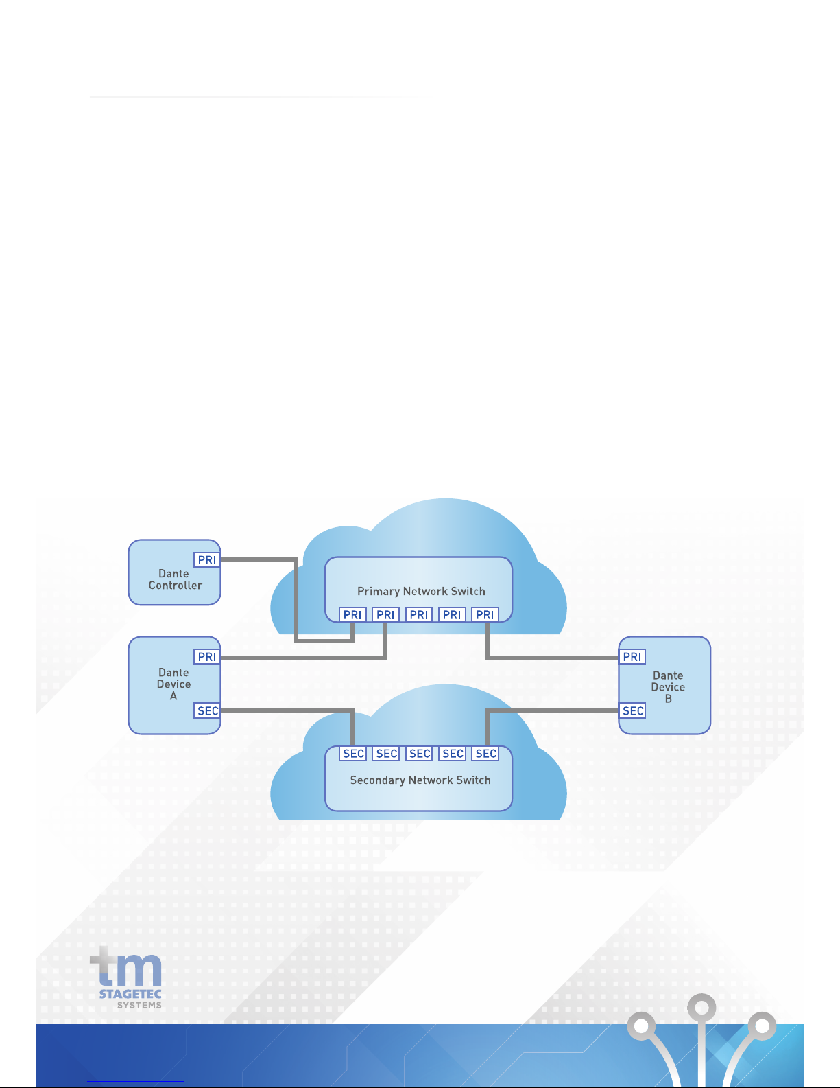
DANTE™ allows you to build a redundant audio network
between devices. This feature has to be activated on the
respective devices (if available). If you decide to use a
redundant audio network there are special requirements to
consider:
• The device which does the configuration must be the
part of the primary network.
• Both networks must have the same link speed. If the
primary network offers a transmission speed of one
gigabit per sec, this must also be available on the
redundant network in order to facilitate automatic
switchover in case of failure.
• If a device is not to be connected with redundant links,
it should be used exclusively in the primary network.
DEVICE SETUP
10
Page 13

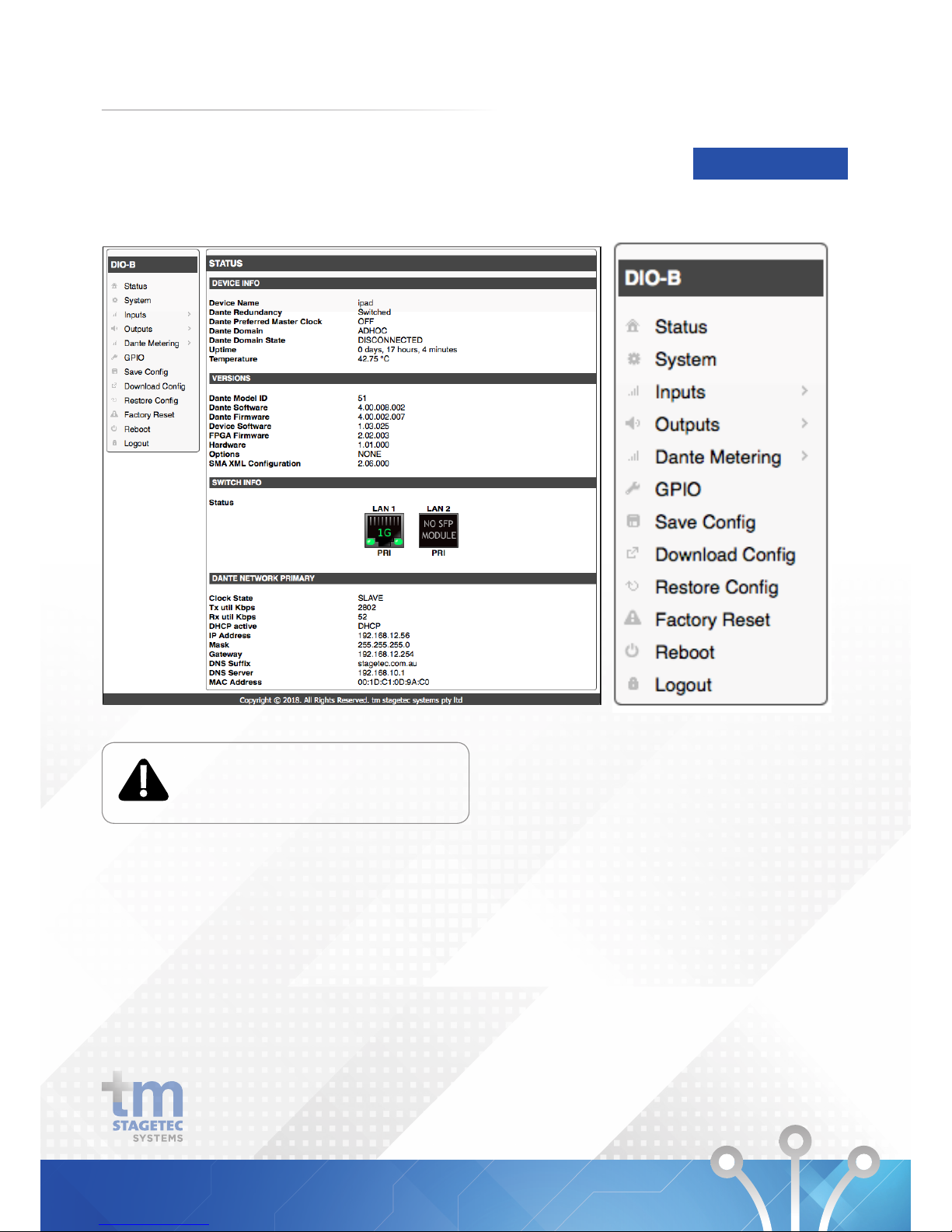
The configuration program is a Web browser-based
configuration interface. You will be guided step-by-step
through the configuration which offers the following
options:
Status
Status information
System
System configurations
Outputs
Configuration of OUTPUTS
Dante Metering
Metering of Dante receivers and transmitters
Save Configuration
Storing the configurations
Download Configuration
Downloading the configurations
Restore Configuration
Restoring configurations
Factory Reset
Restore the device to its default settings
Reboot
Reboot the device
Logout
A configuration session remains active for 30 minutes.
To prevent abuse, please logout after completing the
configuration.
DEVICE SETUP
11
Page 14
Connecting to the DIO
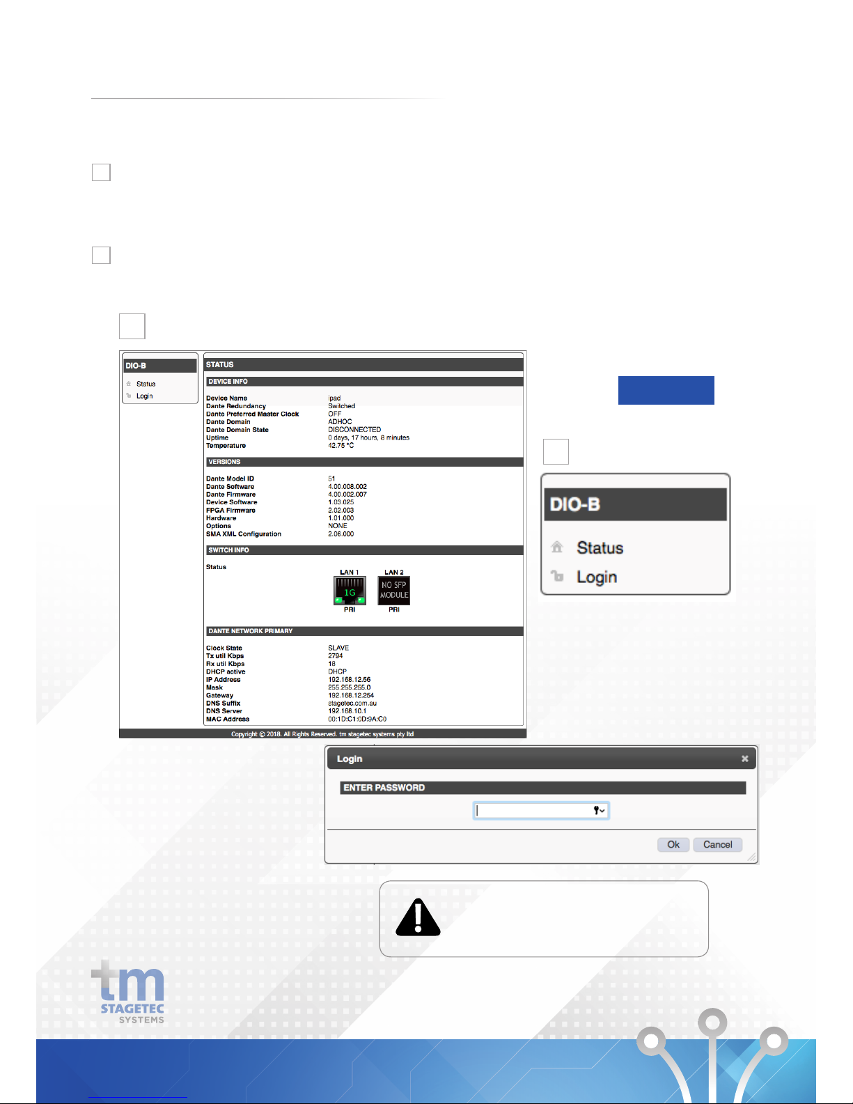
To configure a DIO, open your Web Browser and type the
DIO’s unique IP address into the address bar. Confirm with
the Enter key. The status page of the DIO will appear with
an option to login on the left hand side of the screen.
Click the login option. When the password prompt
appears enter the password. By default, the password
is “password”.
DEVICE SETUP
A configuration session remains active
for 30 minutes. To prevent abuse, please
logout after completing the configuration.
12
Login
1
2
1
2
Page 15
Overview on the configuration program
DEVICE SETUP
Individual settings are only applied when
the system is restarted after saving.
Navigation
13
Page 16
DEVICE SETUP
Individual settings are
only applied when the
system is restarted
after saving.
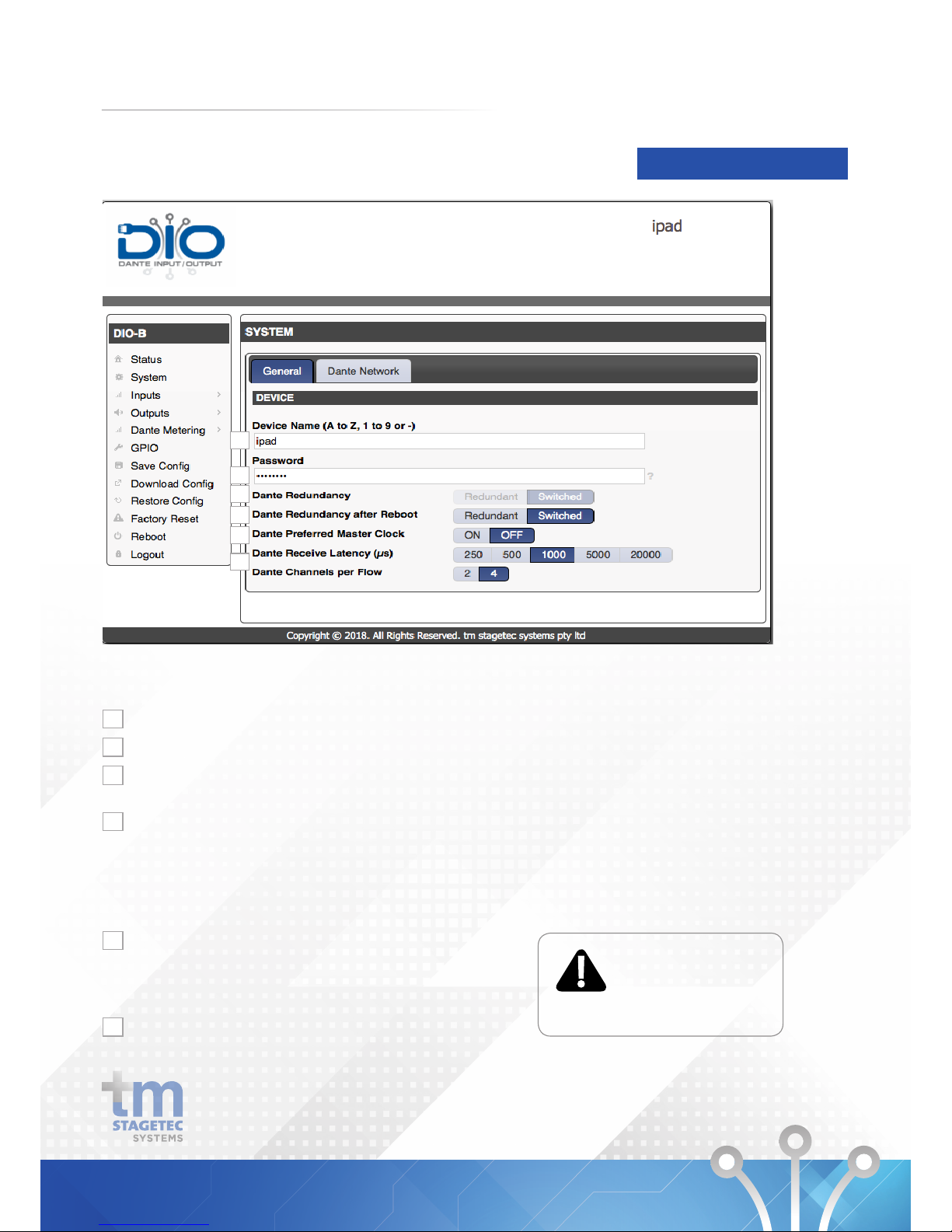
SYSTEM General
Under the menu item SYSTEM General you can configure
following settings:
The name of the device can be edited in this window
The password can be changed
This shows the status of the device’s redundancy.
Please use the option below to change the status.
Change the desired status after reboot of device.
If set to Redundant LAN port 2 is used as the link to the
redundant network, isolated by VLAN.
If set to Switched both LAN interfaces have the same
functions and are linked directly to the internal switch.
Determines clock master.
Here the DIO can be defined as the master clock. If there
is no clock master defined, or several, the device with the
smallest MAC address becomes the clock master.
This determines the latency settings.
1
1
2
3
4
5
6
2
3
4
5
6
14
Page 17
DEVICE SETUP
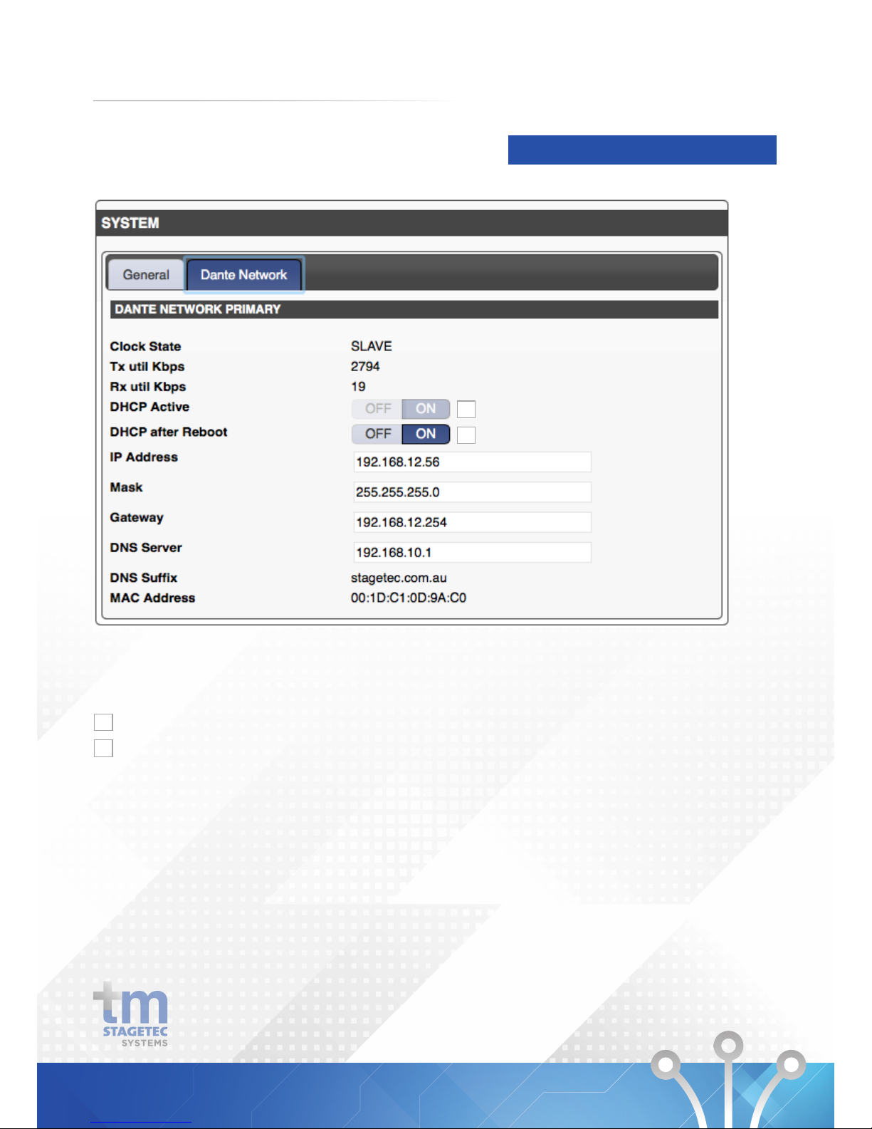
SYSTEM Dante Network
1
2
Under the menu item SYSTEM Dante Network you can
configure the following settings for the Primary and
Secondary network:
Shows the current status.
If DHCP is set to on the IP address is assigned by the DHCP
sever. If no DHCP server is available in the network all
devices with the setting will receive a zero conf address.
If DHCP is set to off the device is configured to use a static
IP address that can be changed in the sections below.
1
2
15
Page 18
DEVICE SETUP
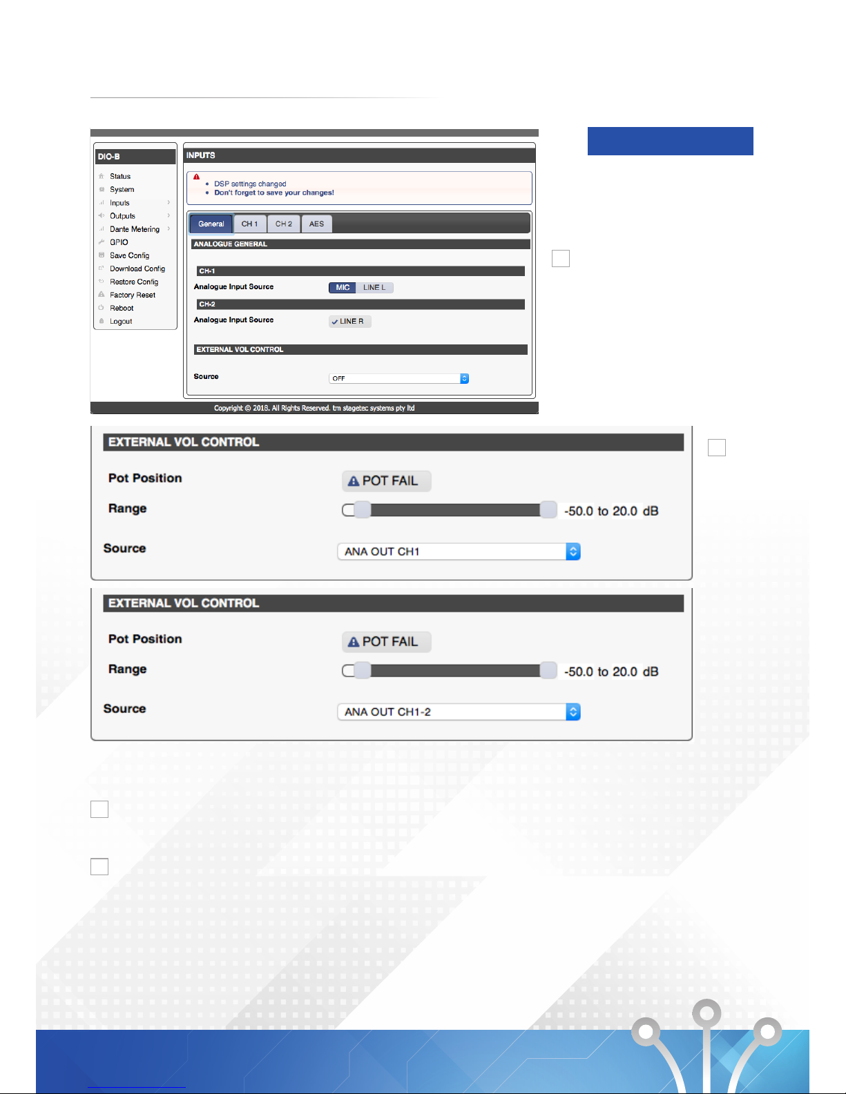
Input General
1
2
Under the menu item Inputs General you can configure the
following.
You can select if the analogue input source for channel 1 is
MIC or Line L. Channel 2’s analogue input source is always
Line R and cannot be changed.
You can select which source you wish to control the volume
of. You may also select the level range that the pot control.
The DIO will indicate the position of the external pot and
can also detect pot failure. When adjusting the external
volume control you will need to refresh the browser to
monitor any changes on the browser.
1
2
16
Page 19
DEVICE SETUP
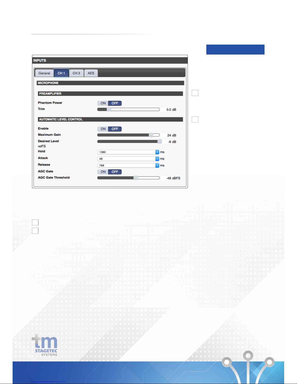
Inputs CH1
1
2
Under the menu option Inputs-General-CH1 you can
configure the following if your channel 1 analogue input
source is set to MIC.
You can enable phantom power and set the input trim
If you enable automatic level control by selecting the on
button. You may set the maximum gain, desired level and
other settings such as Hold, Attack and release. An AGC
Gate (Automatic Gain Control) may also be implemented
and the threshold can be set on this page.
1
2
17
Page 20
DEVICE SETUP
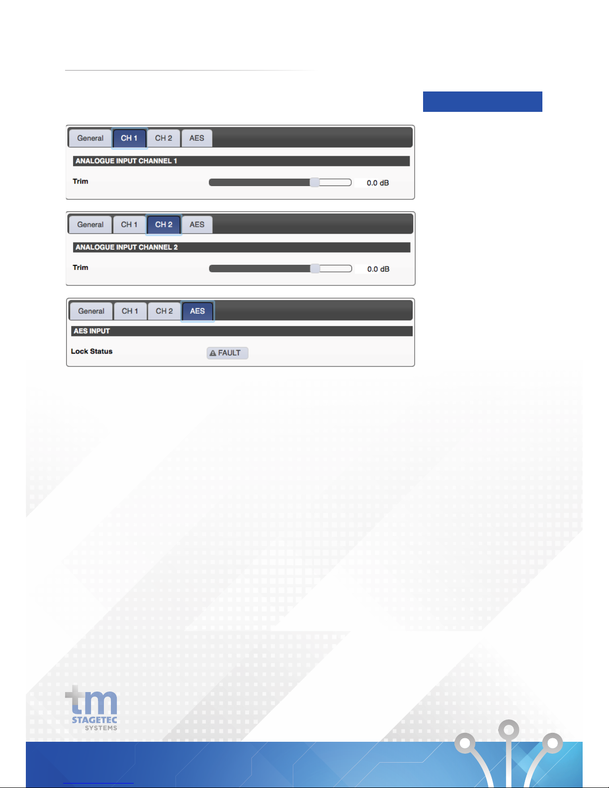
Inputs CH1 & 2
- If CH1 analogue input source is set to Line L you may
only adjust the Trim.
- Under thr tab CH2 in the Inputs menu option you may
adjust the Trim.
- The AES tab under the Inputs menu option will
indicate the Lock Status and the Sync Status of
your AES connection.
18
Page 21
Outputs General
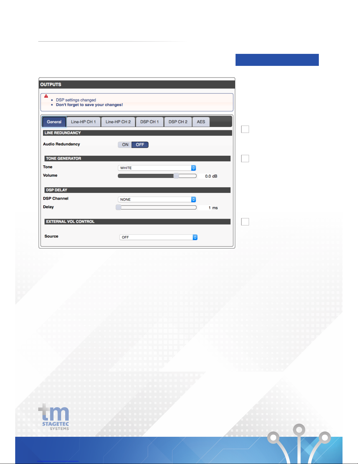
Under the menu option Outputs-General you can configure
the following.
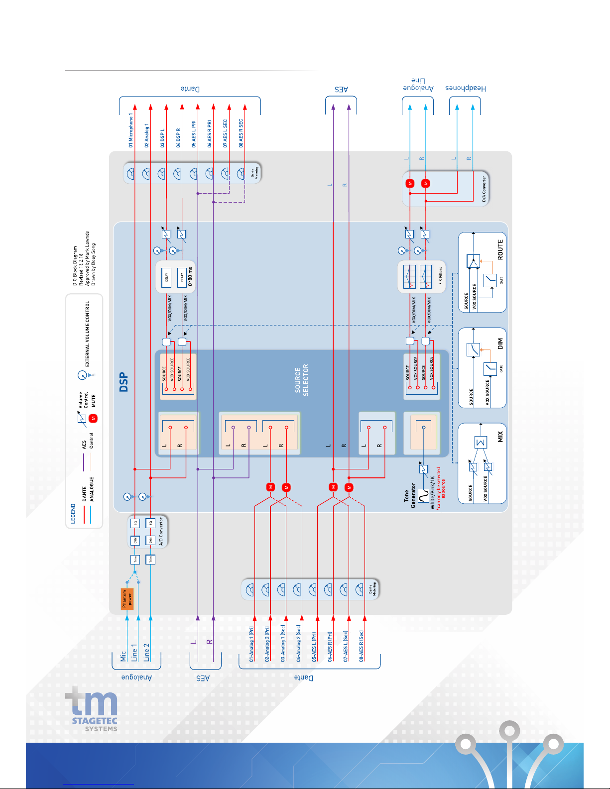
If Audio Redundancy is turned on it will switch between the
Primary and Secondary inputs if required. See the block
diagram in 5. Technical Data.
A Tone Generator is available at each output. On this page
you can select the level of the tone and choose between
white noise, pink noise and a 1kHz sine wave.
This External Volume Control is the same as the Control
available in Inputs - General. It will mirror any changes
made in the input section.
DEVICE SETUP
1
2
3
19
Page 22
Output Analogue & DSP CH 1 & 2
DEVICE SETUP
1
2
3
4
5
6
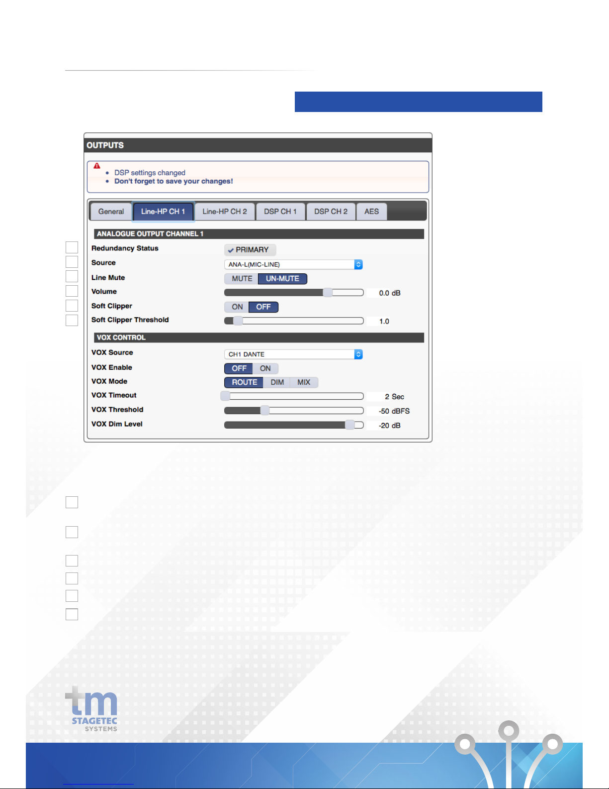
Under the Menu option Outputs- General-Analogue CH1
the following functions are avaialble:
If the DIO’s audio redundancy is on this will indicate if it is
using the Primary or Secondary inputs.
Allows selection of which input source will go to Analogue
CH1 output.
Allows the output to be muted from this page.
Allows control of the output volume.
Select on to activate the Soft Clipper
The Soft Clipper will reduce the peaks of the wave if they
pass the set threshold. The threshold works on a scale of
0-10. Zero being the soft, ten being hard.
1
2
3
4
5
6
20
Page 23
Output Analogue & DSP CH 1 & 2
DEVICE SETUP
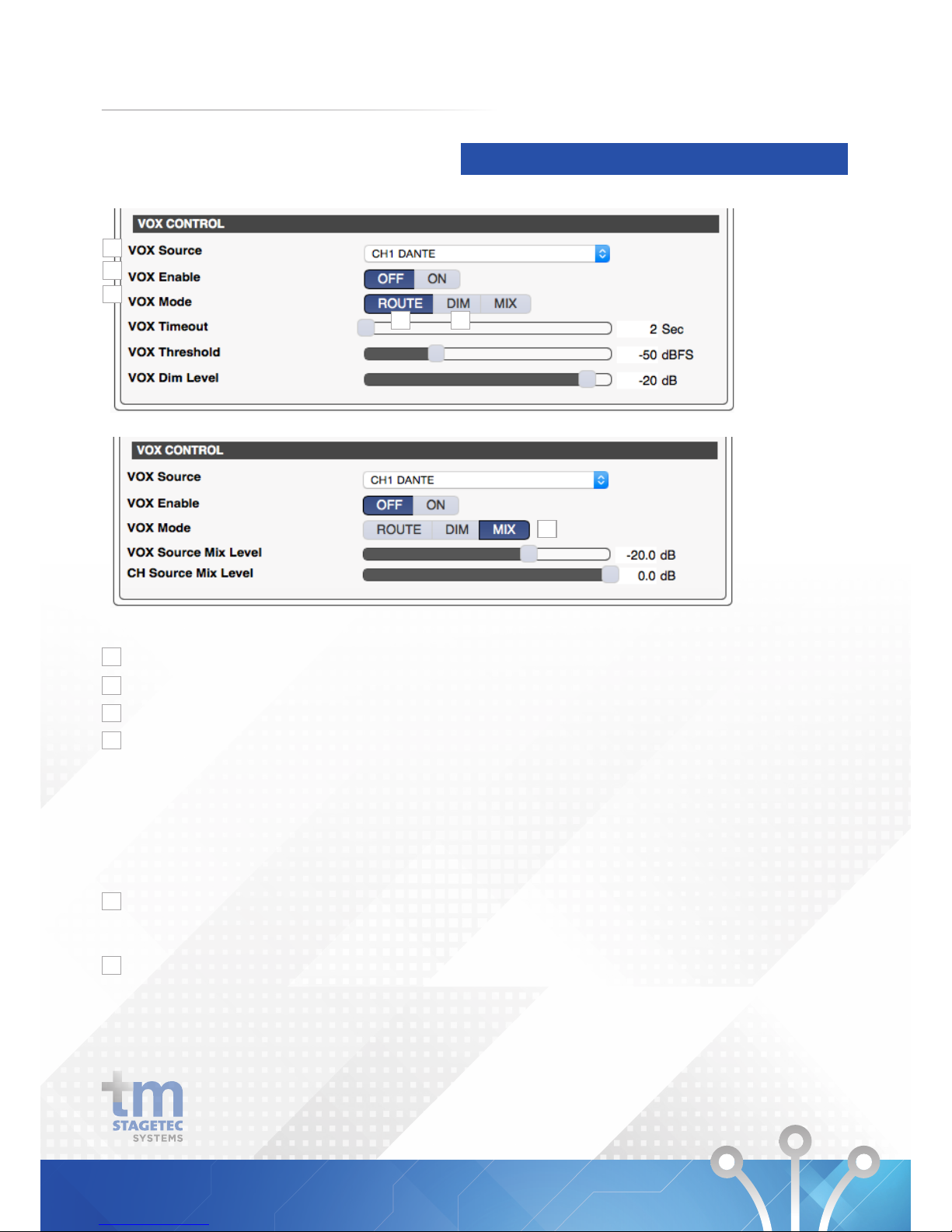
Select which input you wish to be your VOX Source.
Enable Vox function.
Select the VOX Mode.
Selecting the Route Mode will control which source goes
to the output. There is a gate in line with the VOX Source,
when the level is below the threshold the Analogue channel
1 source with be routed. If the VOX Source surpasses
the threshold, it will be routed to the output instead. Vox
Timeout defines the release time of the gate. Vox threshold
defines the Threshold of the gate. The dim option has no
effect in this mode.
When the Vox source surpasses the threshold it will dim
the Analogue output. You can define the release time,
threshold and dim level below.
This mode will mix the channel source and the Vox source.
You can control the level of each source below.
7
8
9
10
11
12
7
8
9
10
11
12
21
Page 24
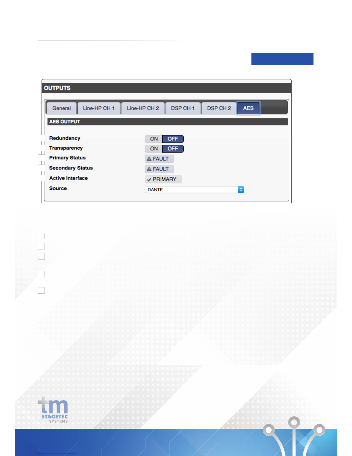
Outputs AES
DEVICE SETUP
1
2
3
4
5
Under the Menu option Outputs-General-AES the following
functions are avaialble:
Indicates if the Primary AES output has a fault.
Indicates if the Secondary AES output has a fault.
Indicates if the Primary or Secondary output is currently
in use
Allows you to activate redundancy between the Primary and
Secondary AES outputs.
Allows you to activate Transparency which will allow the
AES output to also contain data.
1
2
3
4
5
22
Page 25
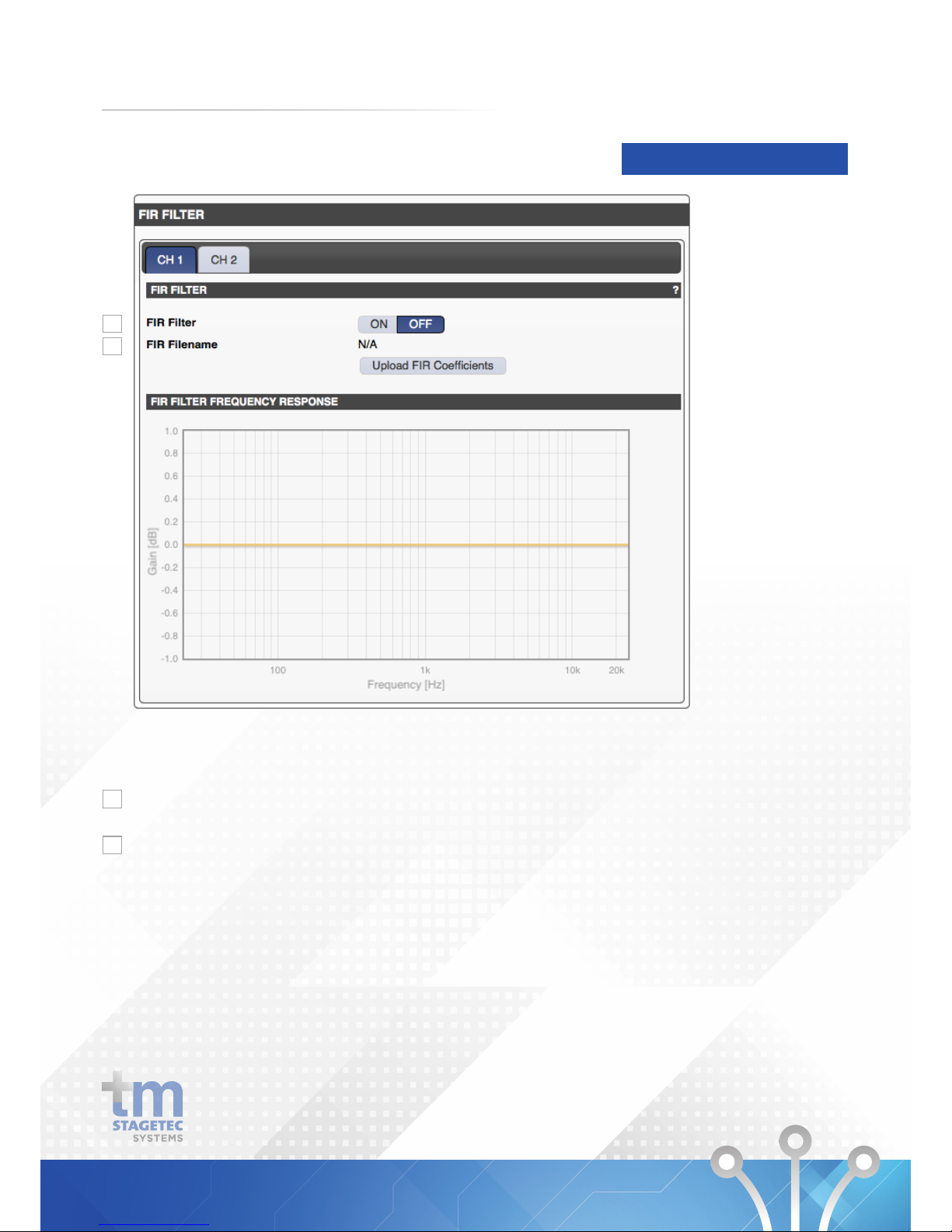
Outputs FIR Filter
DEVICE SETUP
1
2
Under the Menu option Outputs - FIR Filter the following
functions are avaialble:
This allows you to activate an FIR filter on the analogue
outputs
Using this function along with the Upload FIR Coefficients
button will allow you to upload and FIR Filter to the DIO.
FIR Filter Frequency Response will provide a graphic
representation of which frequencies and by how much gain
(dB) the uploaded Filter is affecting.
1
2
23
Page 26
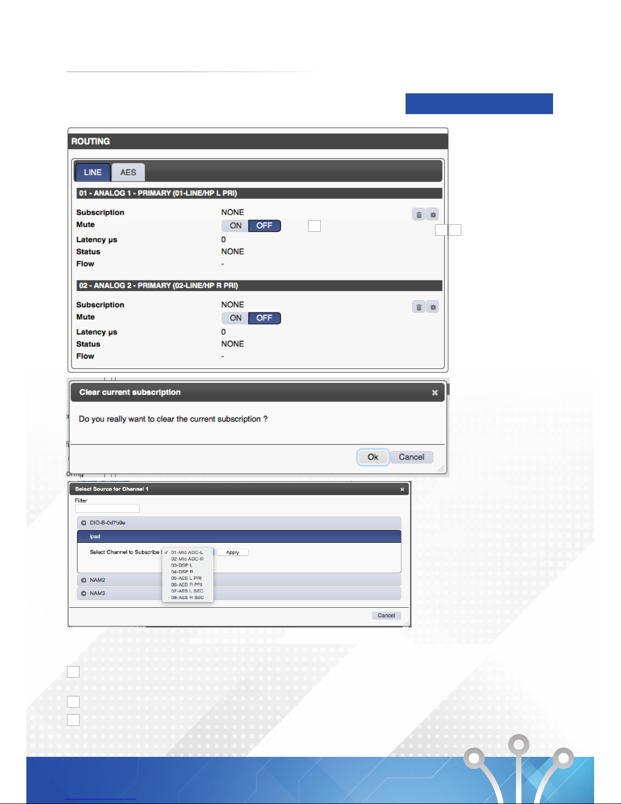
Outputs Routing
DEVICE SETUP
1 2
3
Under the Menu option Outputs - Routing the following
settings are avaialble for Line and AES outputs:
Use the trash can symbol to clear the subscription of the
respective Dante output.
Use this button to select the input signal of the respective
Enables or Disables the output.
1
2
3
24
Page 27
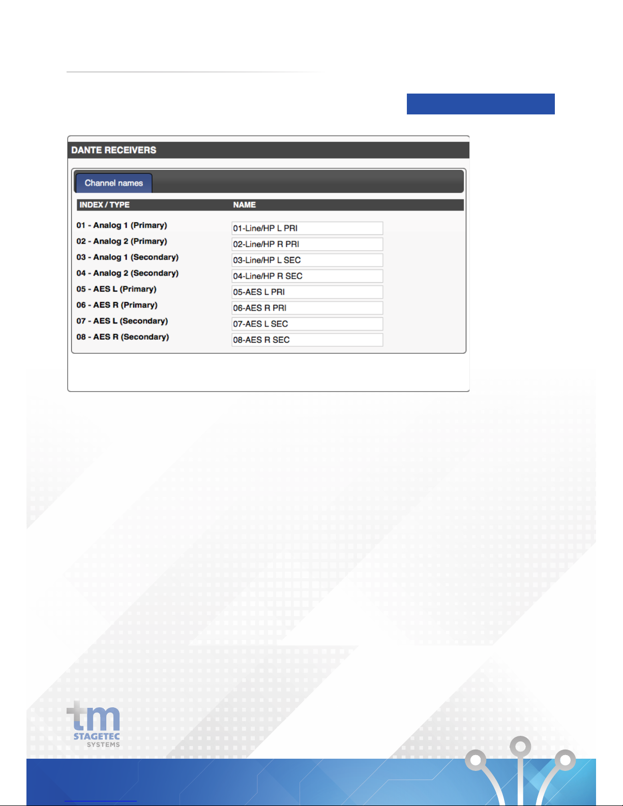
Outputs Names
Under the Menu option Outputs - Names you are able to change the name of each output.
DEVICE SETUP
25
Page 28
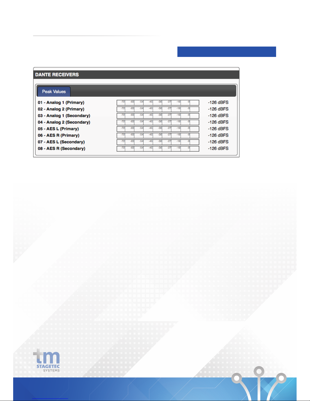
Dante Metering Receivers
Under the Menu option Dante Metering - Receivers you are able to access the level meters for each input.
DEVICE SETUP
26
Page 29
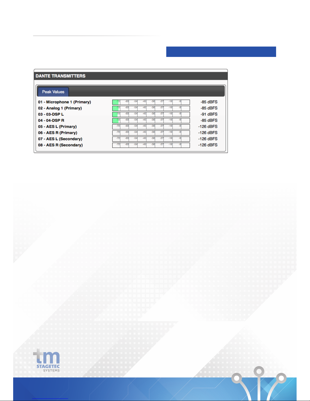
Dante Metering Transmitters
Under the Menu option Dante Metering - Transmitters you are able to access the level meters for each output.
DEVICE SETUP
27
Page 30
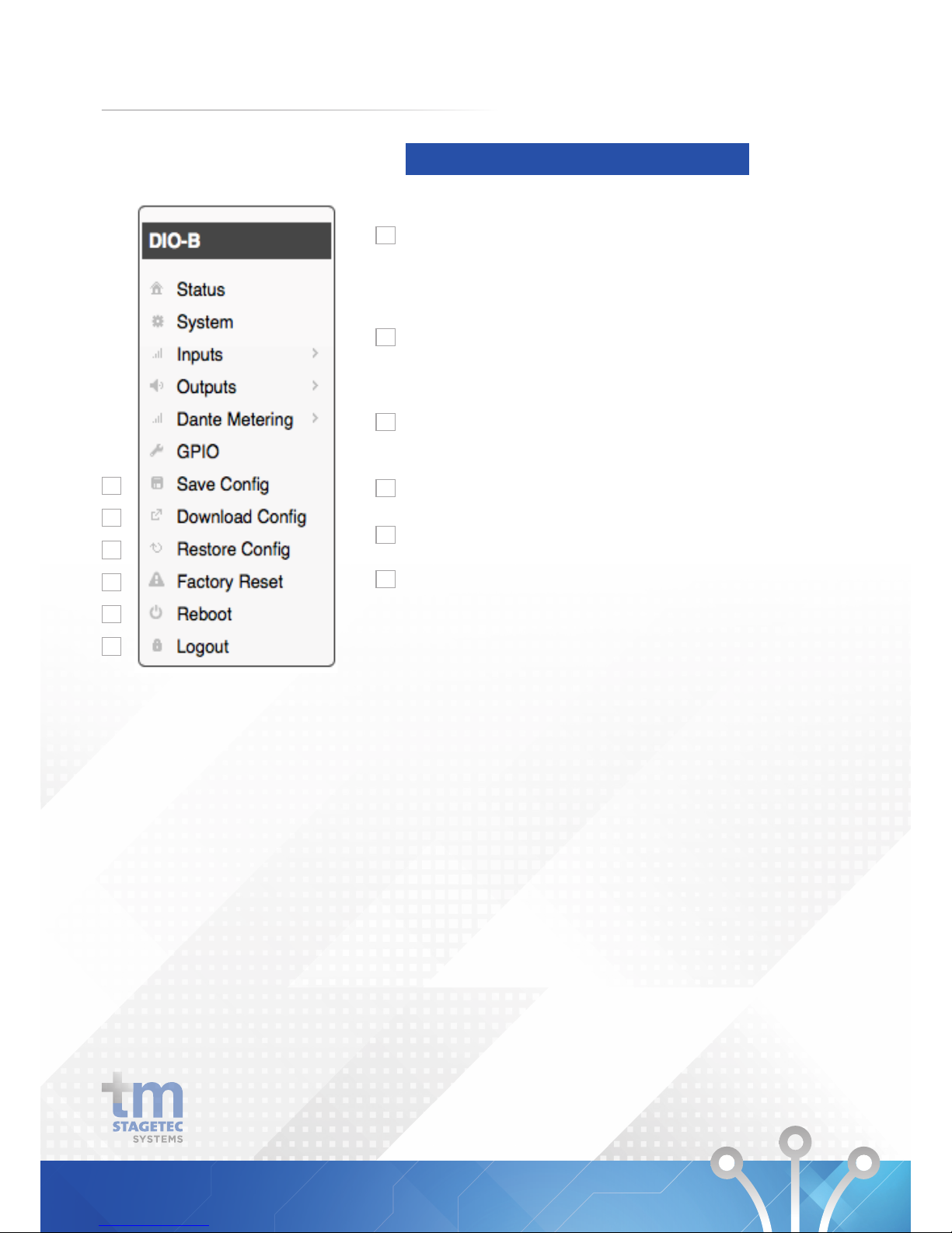
Additional Navigation Menus
DEVICE SETUP
1
2
3
4
5
6
Save Configuration
All changes made are available temporarily (other than
those which require a reboot). If the settings remain static,
the configuration must be saved to the unit. If not the DIO
will resolve to last saved settings after a reboot.
Download Configuration
The configuration which was saved last within the DIO will
be transferred to the connected PC and can be named and
saved there.
Restore Configuration
Uploads a previously saved configuration to the unit and
reboots it.
Factory Configuration
Returns all settings back to the factory default
Reboot
Will reboot the device.
Logout
Will logout of the device’s web browser interface.
1
2
3
4
5
6
28
Page 31
5. TECHNICAL DATA
29
Page 32
TECHNICAL DATA
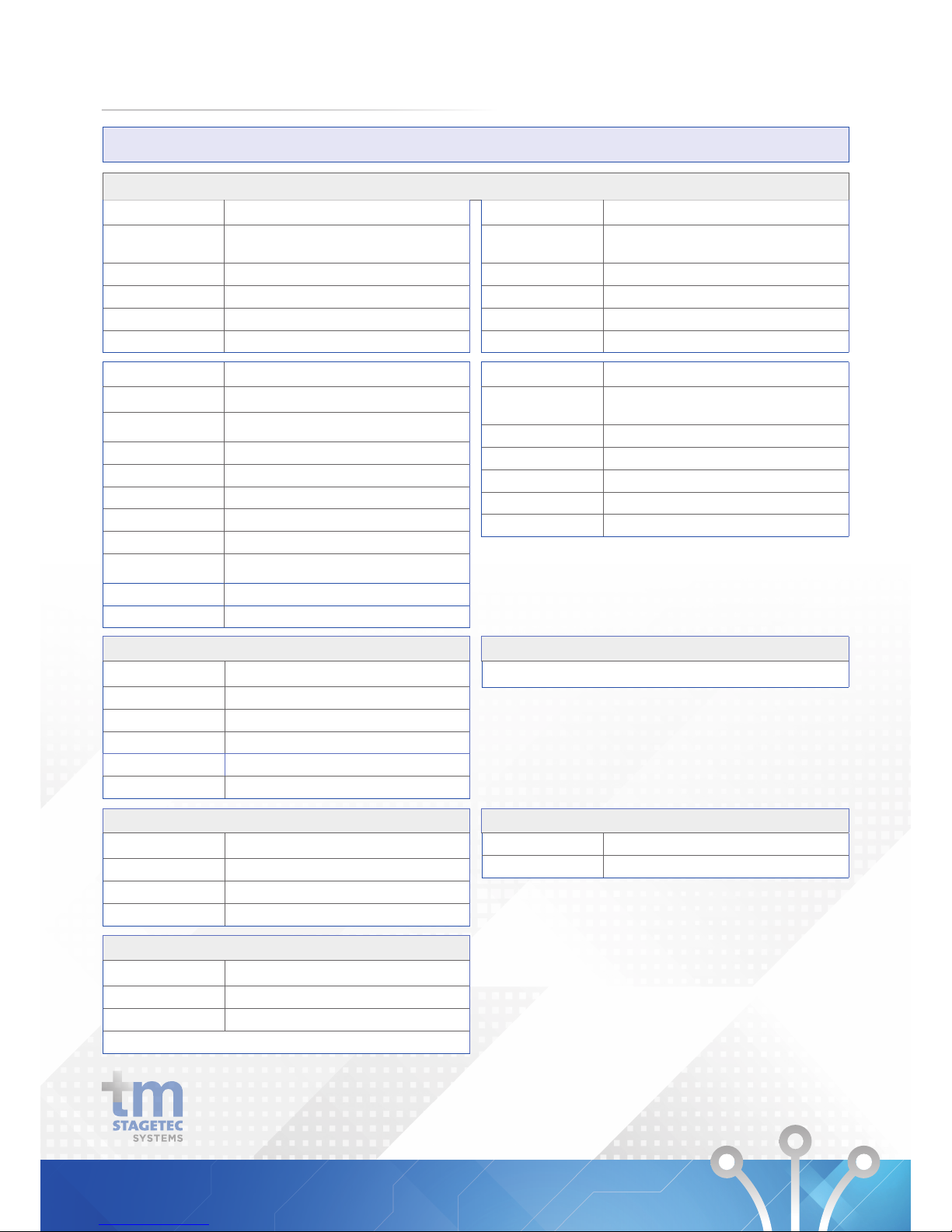
DIO Specifications
Analogue Audio
Balanced Inputs (D25 Connector)
Channels Sample
Rate
2 x Balanced, Max input level +24dBu 48 kHz
(24bit)
Dynamic Range > 95dB (A weighted)
THD < -83dB lkhz +18dBu input,-6dBFs output
Frequency Response 20Hz - 20kHz
Channel gain control +6dB to -12dB in 0.5db increments
Balanced Inputs (D25 Connector)
Channels
2 x Balanced, Max input level +24dBu 48 kHz
(24bit)
Sample Rate of A/D > 95dB (A weighted)
Dynamic Range <-86dB 1khz -6dBFs , 18dBu output
THD 20Hz - 20kHz
Frequency Response +20dB to -57dB in 0.5db increments
Input (Microphone) (Phoenix Connector)
Input Gain Block +55.5 to -12dB in 0.75db lncrements
Dynamic Range
> 95dB (A weighted) unity gain ,-112 dBu EIN
150ohm reference -50dBu input level
Frequency Response 20Hz - 20kHz
THD < -80dB 1khz OdBu input ,-3dBFs output
Attack TC 6ms to 2000ms
Release TC 24ms to 786430ms
Hold 2ms to 87491ms
Noise Gate
Threshold
30 to -77db relFS
Phantom Power +48v selectable
External DC output +24v 40ma
Digital Audio
Input (RJ45 Connector)
Sample Rate 48 kHz (32bit)
Modes Transparent / Non Transparent
Redundancy 2 x Buffered inputs (via Dante)
Output (RJ45 Connector)
Sample Rate 48 kHz (32bit)
Ethernet
Input (RJ45 Connector)
Sample Rate 48 kHz (32bit)
Modes Transparent / Non Transparent
Redundancy 2 x Buffered inputs (via Dante)
Power
External 12-48 Volts
Power Over Ethernet POE Switch required
Power 10 watts
Redundancy power is provided between both inputs
GPIO
Inputs 2 x Opto Inputs - Max 5mA Sink
Outputs x lsolated Outputs - 200V Max 150mA
Headphone Amplifer (D25 Connector)
Channels
2 eh , 15vpp 2200hm load, 8vpp 50ohm load,
short circuit protected
Dynamic Range > 97dB (A weighted)
Frequency Response 20Hz - 20kHz
THD < -85dB 1khz -6dBFs
Soft Clipper 0.1 to 10, in 0.1 increments
External Val Control Channel and gain range selectable
Message Player (Option)
WAV, MP3 Message player triggered by GPIO or UDP protocol
30
Page 33
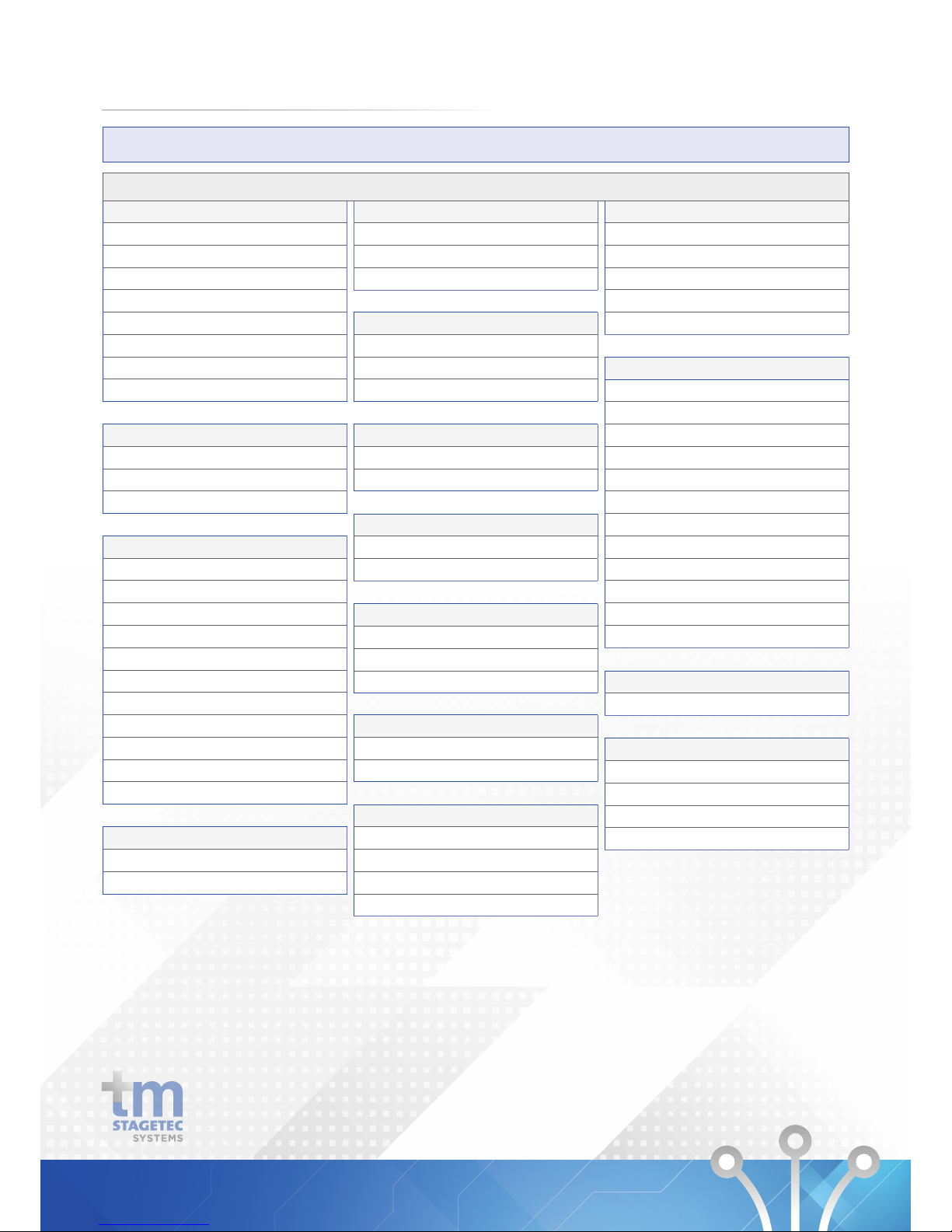
Counters
Stop Watches
Counters
Pulse Counter
TECHNICAL DATA
DIO Specifications
Filters
First and Second Order IJR
Single and Double Precision llR
Crossover (2 & 3 way)
Tracking Filter
DC Blocking
De-emphasis
State Variable
FIR - 2 X 1000 Point
GPIO Conditioning
Push Button Volume Control
Rotary Encoder Volume Control
Up/Down Table
Muxes, Demuxes
Switches
Multiplexers
Demultiplexers
Sources
DC
Beep
Sine, Square, Triangle, Sawtooth Waves
VCO
Project Design Tools
Image, Comment insert
Hierarchy design support
Filter magnitude/phase response
Support for MLSSA response files
Level Detectors, Lookup Tables
Level Detectors
Lookup Tables
Mixers, Splitters
Mixers
Splitters
Hard/Soft Clipping
Hard Clipping
Soft Clipping
Dynamics Processors
Peak Detector
RMS Detector
Limiter
Volume Controls, Mute
Volume Control
Mute
Advanced Algorithms
Chime Design
Flanger
Vocal Chorus
Reverb
Dynamic Bass
Loudness
Midnight Mode
Phat Stereo
SuperPhat Spatializer
Enhanced Stereo Capture
Wind Noise Detection
Square Root
Clipper
AB in/out Condition
Tolerance Analyser
Logic - And, Or, Nand, Nor
lnvert
One-Shot
Linear Gain
Value Cross Detection
Linear lnterpolator
Delay
Voltage Controlled Delay
Readback
Value Hold
Signal lnvert
Basic DSP
Absolute Value
Signal Add
Signal Subtract
Divide
Multiply
31
DSP Options
Page 34
TECHNICAL DATA
DIO Specifications
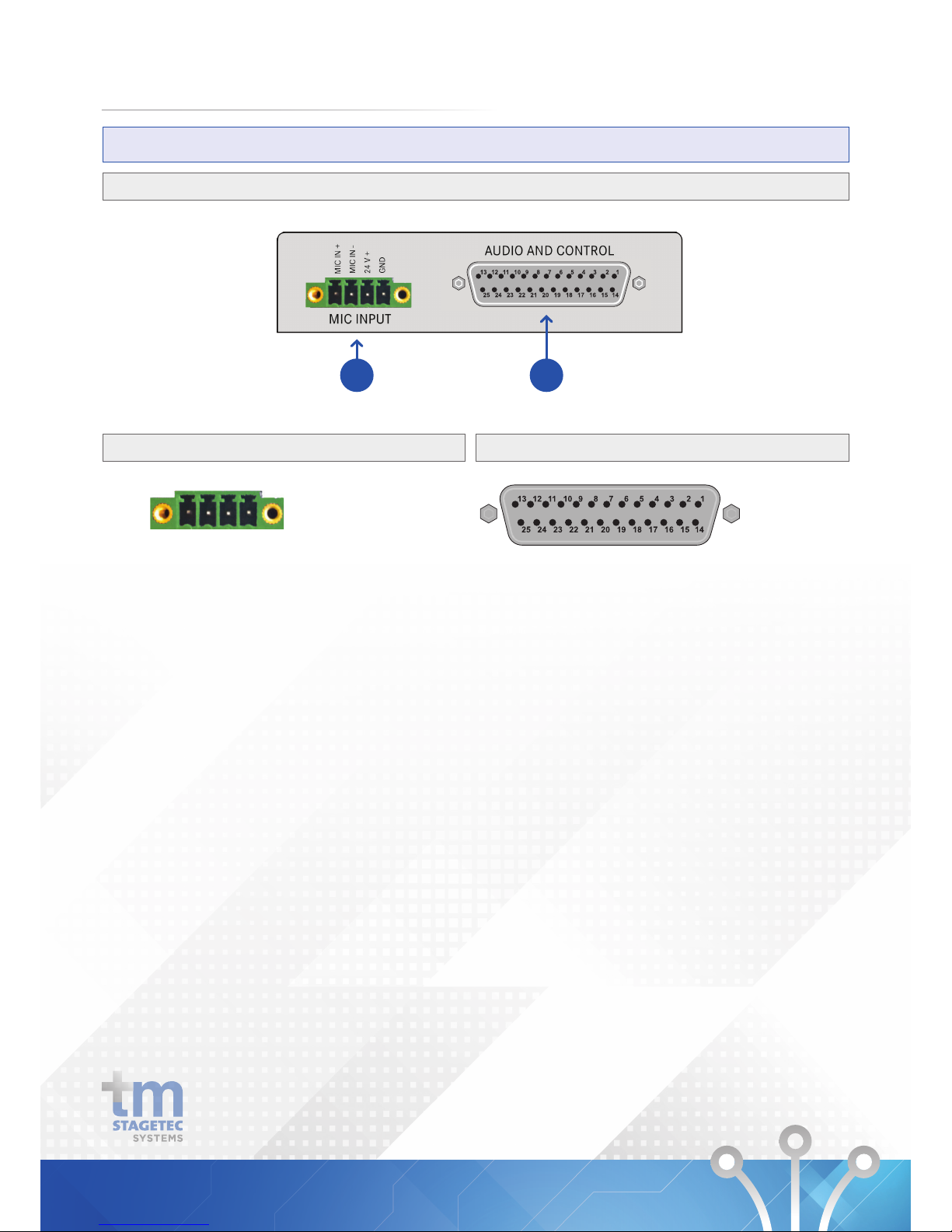
PINOUTS
1
Mic Input
2
Audio and Control
1: MIC IN +
2: MIC IN -
3: GPI VE
4: GND
1 2 3 4
1: GPI VE +24
2: GPI 1/2 CA
3: GPI 1
4: GPI 2
5: GND
6: GND
7: R OUT+
8: L OUT+
9: GND
10: R IN+
11: L IN+
12: GND
13: L HP
14: GPO 1/2 CE
15: GPO 1
16: GPO 2
17: VCA C
18: GND
19: R OUT -
20: L OUT -
21: GND
22: R IN -
23: L IN -
24: GND
25: R HP
32
1 2
Page 35
TECHNICAL DATA
DIO Specifications
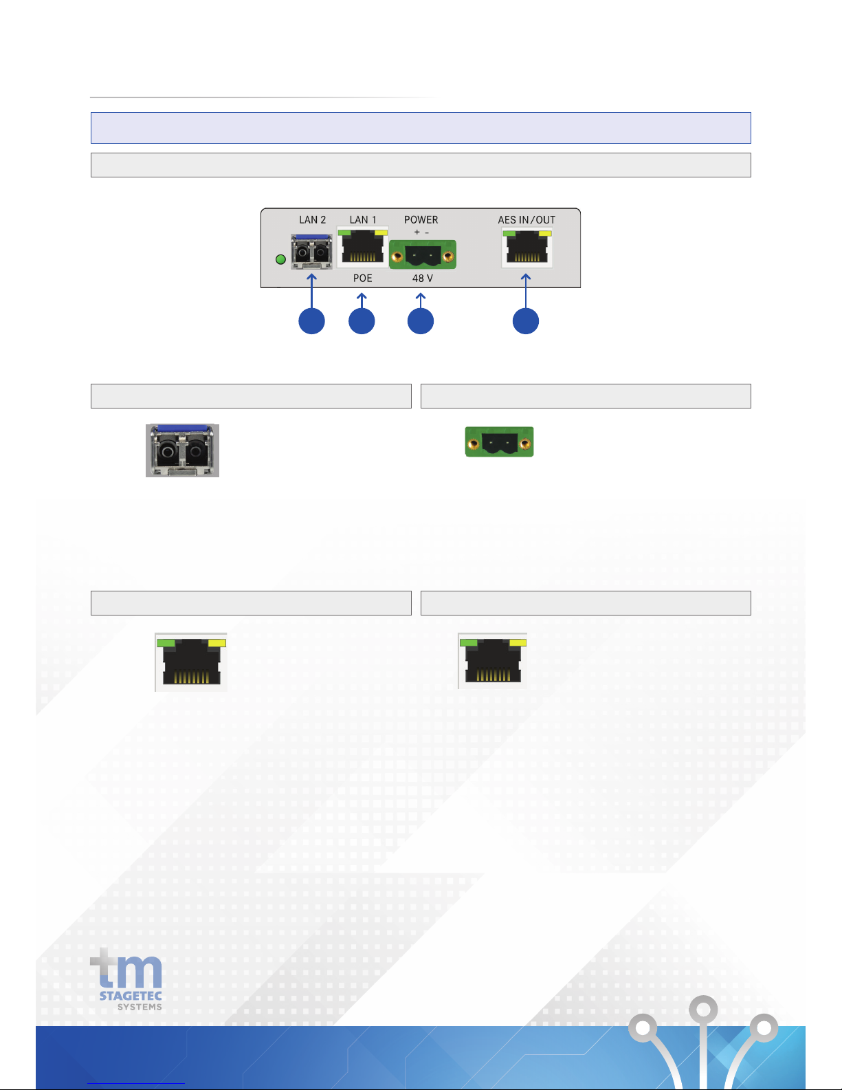
PINOUTS
3
SFP Cage (1 Gbit Switch)
*SFP not included
4
LAN with POE (1 Gbit Switch)
5
Power
6
AES
3 4 5 6
1 2
1: DC +
2: DC -
Suitable for:
1. Single mode fibre
2. multi mode fibre
3. Copper SFP’s
1: TxRx A+ [Model A: DC+]
2: TxRx A- [Model A: DC+]
3: TxRx B+ [Model A: DC -]
4: TxRx C+ [Model B: DC+]
5: TxRx C- [Model B: DC+]
6: TxRx B- [Model A: DC -]
7: TxRx D+ [Model B: DC -]
8: TxRx D- [Model B: DC -]
GND: CHASIS
87654321
1: AES TX +
2: AES TX -
3: 4: EDC FLAG
5: 232 RX to DIO
6: 232 TX from DIO
7: AES RX +
8: AES RX -
GND: CHASIS
87654321
33
Page 36
TECHNICAL DATA
DIO Specifications
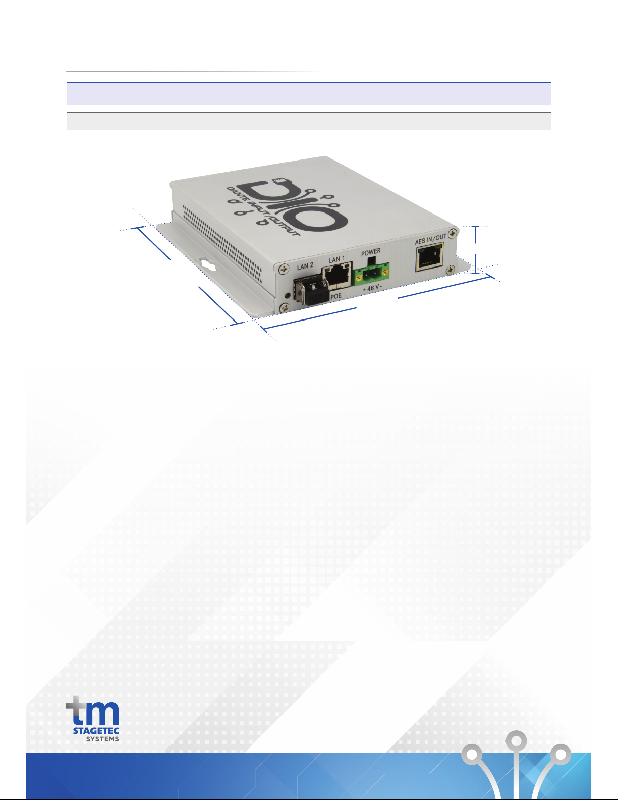
Dimensions
145mm
130mm
27mm
34
Unit 6, 476 Gardeners Rd, Alexandria, NSW 2015 Phone +612 8011 0500 Email info@tm-systems.com.au
 Loading...