

Page 1
92-1000-0201-0-1-0
REV 1
EN
Last update: 2019-06-13
USER MANUAL
REF
Page 2

USER MANUAL SAGA
TABLE OF CONTENTS
1 SERVICE AND SUPPORT 3
About this manual 3
Contact information TMSi 3
W arr anty inf or mati on 3
Additional accessories or spare parts 4
Abbreviations 4
2 SAFETY INFORMATION 5
Explanation of mar kings 5
Limitations of use 6
Safety measures and warnings 6
Precautionary measures 7
Discl osure of r es id u al ris k 7
Information f or lays 7
Safety information f or IT-network 7
3 PRODUCT OVERVIEW 8
Product 8
Intended use 8
Product views 10
User interf ac e 15
Connections 18
Internal 3D accelerometer 19
Synchronisation Output 19
Device labels 20
Spare parts – order information 20
4 INSTRUCTIONS FOR USE 21
Power the Docking Station 21
Power the Data Recorder 21
Charge batteries 22
Docking mechanism 22
Con nect ac c essories 23
Dat a conn ecti ons 24
Sof twar e 25
SAGA Bracket 26
5 Perform a measurement 27
Perform Stationary Measurement 27
Perform Portable Measurement using W ireless connection 28
Perform Portable Measurement using Optical Fiber 29
Perform Ambulatory Measurement 29
Impedance Measurement 30
Recovery of lost data 31
Status E vents 32
6 Operational Principles 34
SAGA Device 34
Unipolar input channels 34
Reference 34
Bipolar input channels 35
Auxiliary input channels 35
Tips for obt aining optimal quality data 35
7 MAINTENANCE 37
Servicing and U pdates 37
Cleaning instructions 37
Disposal instructions 37
8 ELECTROMAGNETIC GUIDANCE 38
Degradation of perf ormanc e 38
Electromagnetic emission 39
Electromagnetic immunity 39
9 TECHNICAL SPECIFICATIONS 42
Page 2 of 47
Page 3

USER MANUAL SAGA
Contact Information
Twente Medical Systems International B.V.
Zutphenstraat 57
support@tmsi.com
www.tmsi.com
1 SERVICE AND SUPPORT
About this manual
This manual is intended for the user of the SAGA 32+/64+ system – referred to as
‘product’ throughout this manual. It contains general operating instructions,
precautionary measures, maintenance instructions and information for use of the
product. Read this manual carefully and familiarize yourself with the various controls
and accessories before starting to use the product.
Contact information TMSi
TMSi Support can be reached via email (support@tmsi.com) or via our website:
www.tmsi.com/support. Please provide as much information as possible, including
serial numbers of the used products. This will help us to support you in the best way
possible.
7575 EJ Oldenzaal
The Netherlands
Warranty information
The product, except its cables and accessories, is warranted against failure of
materials and workmanship for a period of 2 years from the date of delivery. Cables
and accessories have a warranty period of 6 months.
Repairs can only be performed by the manufacturer or by TMSi authorized
personnel. Warranty will terminate automatically by removal or alteration of
identification labels on the product or its parts. In case seals on the enclosure are
broken or removed, warranty is voided and TMSi can no longer guarantee continued
safety or correct operation of the product.
The warranty does not cover the following:
• Failure resulting from misuse, accident, modification, unsuitable physical or
operating environment, or improper maintenance.
• Wear and tear caused by regular and normal usage and ageing of
rechargeable batteries.
• Failure caused by a product for which TMSi is not responsible.
• Damage resulting from use of non-approved accessories.
• Uninterrupted or error-free operation of wired or wireless data
transmission.
Any technical or other support provided for a product under warranty, such as
assistance with “how-to” questions and those regarding device set-up and
installation, is provided without warranty.
Page 3 of 47
Page 4

USER MANUAL SAGA
AUX
EEG
Electro-encephalography (Brain activity)
EMG,
HD EMG
Electromyography (Muscle activity),
REF
SN
UNI
Additional accessories or spare parts
In case you want to order additional accessories such as cables or sensors or spare
parts such as batteries, please contact
quotation.
sales@tmsi.com for consultation and a detailed
Abbreviations
Abbreviation
Auxiliary
BIP Bipolar
BOB Break-Out-Box
CF Cardiac Floating
CE Conformité Européenne
DS Docking Station
DR Data Recorder
EM, EMC Electro-magnetic, Electro-Magnetic Compatibility
High-Density Electromyography,
ECG Electrocardiography
EOG Electro-oculography
IT Information Technology
LAN Local Area Network
PC Personal Computer
Reference
RF Radio Frequency
Serial Number
TMSi Twente Medical Systems International B.V
Unipolar
USB Universal Serial Bus
Page 4 of 47
Page 5
USER MANUAL SAGA
2 SAFETY INFORMATION
This section contains general warnings, explanation of markings, limitations of use,
safety measures and precautionary measures important for safe use of the product.
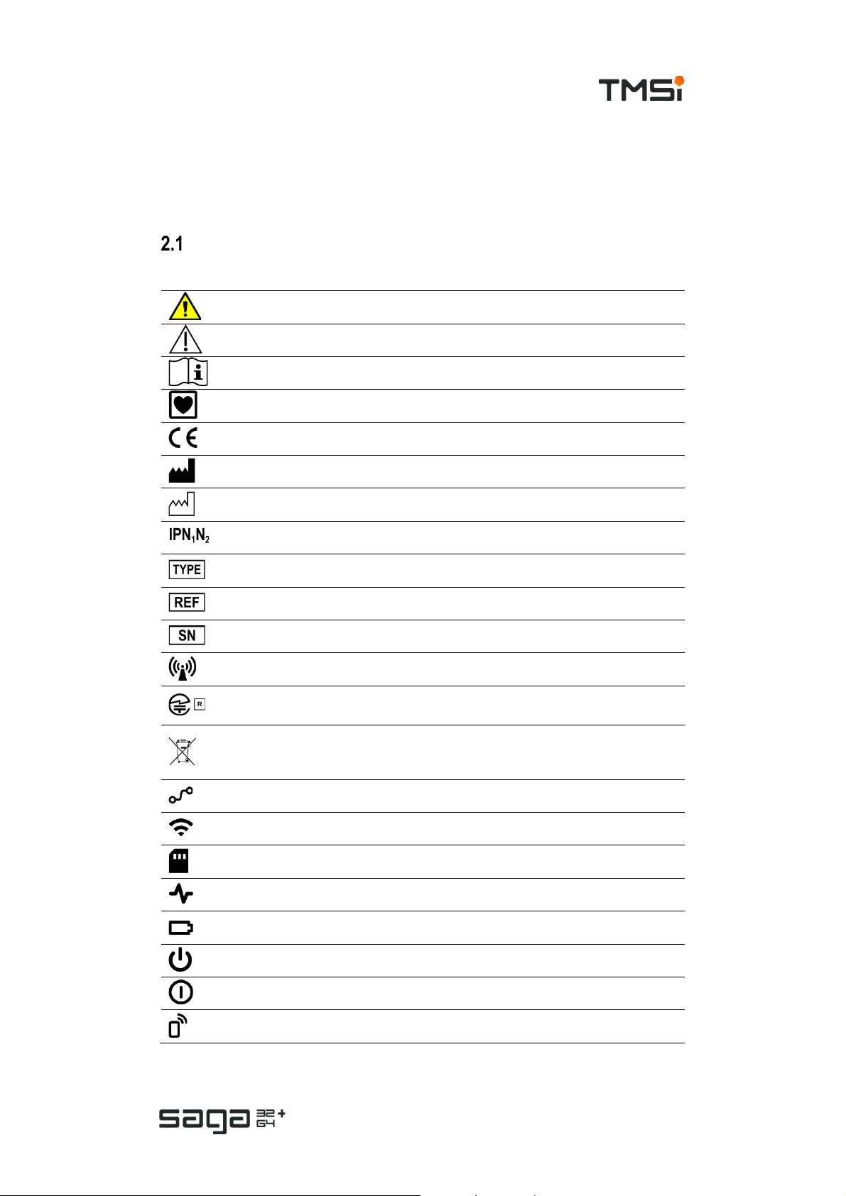
Explanation of markings
This section explains the various markings and symbols used with the product.
Warning: read important s afety information
Caution
Consult instructions for use
Type CF applied part
CE-certified, see declaration of conformity
Identification of the manuf actur er
Year of manuf acturing
Ingress protection rating
TMSi Type identification
TMSi referenc e number
TMSi serial number
Contains trans mitter module
Contains radio module for which the T echnic al Regulations Conformity Certific ation has
been granted
Special EU instructions for disposal are applicable to a product on which this symbol is
placed. The Maintenance s ection of this manual contains information on how to dispose
of this product
Wired connection status indicator; see chapter 3.3
Wi-Fi connection status indic ator; s ee chapter 3.3
On-board memory status indic ator; s ee chapter 3.3
Signal Mode status indicator; see chapter 3.3
Battery status indic ator; all status indicators are explained in chapter 3.3
Stand-by symbol
Power status indic ator; all status indicators are explained in chapter 3.3
Remote Interface status indicator; all status indic ators are explained in chapter 3.3
Page 5 of 47
Page 6
USER MANUAL SAGA
Limitations of use
There are no known contra-indications to the use of the SAGA product. For further
information refer to chapters 2.3, 2.4 and 3.2.
• This product is not intended for use in a life supporting system.
• This product is not defibrillator-proof.
• This product is not intended for use in oxygen rich envir onments or in combination with
anaes thet ic g asses.
• This product is not compatible with HF surgic al equipment.
• This product is not intended for us e on altitudes higher than 3000 m above s ea level.
• This product is not to be used in the presence of Magnetic Resonanc e Imaging (MRI)
devic es .
Safety measures and warnings
Connect the mains power adapter onl y to a supply mains with protective earth to a void the risk of
electric shock.
Only use the SAGA prod uct with the supplied mains power adapter or a replacement explicitl y
approved by TMSi to avoid the risk of electric shock.
Only use accessories explicitly approved by TMSi to avoid the risk of electric shock.
Do not connect equipment that is not IEC 60950 compliant to SAGA to a void the risk of electric
shock.
Do not touch pins of removed batteries or of disengaged connector plugs or sockets to avoid the
risk of electric shock.
Do not use any other than the designated battery type with SAGA to avoid the risk of electric shock
and damage to it.
Do not use SAGA together with cautery or electro-coagulation equipm ent on the same subject to
avoid damage to the product.
Do not use or store n ear sources with particle radiation or elevated levels of electrical, m agnetic or
electro-magnetic fields to avoid dam age to the product.
Only connect T MSi approved accessories and equipment to SAGA to avoid dam age to it and
reciprocal interference.
Do not use SAGA togeth er with magnetic resonance imaging equipment on the same subject to
avoid reciprocal interference.
Do not tamper with an y part of SAGA. No modifications are allowed to maintain safety.
Use of SAGA adjacent to or stacked with other equipment should be avoided because it could
result in improper operation. If such use is necessary, SAGA and the other equipment should be
observed to verif y that they are operating normally.
Use of accessories, transducers and cables other than those specified or provided by the
manufacturer of SAGA could result in increased electromagnetic emissions or decreased
electromagnetic immunity of SAGA and result in i mproper operation.
Portable RF communications equipment (including peripherals such as antenna cables and
external antennas) should be used no closer than 30 cm (12 inches) to any part of the SAGA
including i ts cables. Otherwise SAGA performance degradation could result.
Page 6 of 47
Page 7
USER MANUAL SAGA
Precautionary measures
Whenever data availability is important make sure the Data Recorder contains at least one sufficiently
charged battery as a bac kup for mains power failure.
Make sure sufficiently charged batteries are inserted before ambulatory use of SAGA. If necessary,
provide for extra fully charged batteries for swapping.
Remove batteries from SAGA if it is not likely to be used for some time.
To prolong batter y life, store them preferably at 40 % charged state and at a temperature in the range
(-20 to 20) °C.
To avoid signal disturbance, keep SAGA away from sources of strong electric, magnetic and
electromagnetic radiation.
To avoid loss of data use wired communication for data transport and control.
Route cables for a comfortable wear and freedom of movement for the subject; properly secure any
excess cable, for example with some tape or Velcro.
Prevent prolonged physical contact with metal connector parts as they may contain nickel. If
necessary, tape them off using for example a band aid.
If any part of SAGA appears obviously malfunctioning or damaged, refrain from further using it and
contact the manufacturer for repair and check of the device.
SAGA is not defibrillation-proof equipment. T o avoid damage to it, disconnect it fully from the subject
before applying defibrillation shocks.
In order to isolate SAGA from the supply mains, disconnect the m ains power adapter from the SAGA
Docking Station or disconnect the supply cable of the mains power adapter on at least one end.
Make sure that at least one of these options is easily accessible.
Disclosure of residual risk
The intended and foreseeable use of the SAGA product bears an acceptable risk.
No specific residual risks need to be disclosed.
Information for lays
The user of the product shall instruct lay operators of the product on the following
topics:
• Contr a-indications on the use and usage environments.
• Which indicators, if any, must be monitored, how often, and how to react on specific status
indications.
• When to press the Event marker button.
• Specific ally: how batteries must be exchanged and recharged, if their running out is expected.
Safety information for IT-network
Connection of SAGA t o an IT-network that includes other equipment could result in previously
unidentified risks.
The customer should identify, analyse and control these risks.
Subsequent changes to the IT-network could introduce new risk and require additional analysis.
Such changes to the IT-network include: Changes to configuration, connecting or disconnecting items,
update or upgrade of connected equipment.
Page 7 of 47
Page 8

USER MANUAL SAGA
3 PRODUCT OVERVIEW
Product
The product consists of the following components:
• SAGA 32+/64+: (Electro-)physiological amplifier consisting of:
o Data Recorder.
o Docking Station.
• Accompanying documentation: User Manual and certificates.
• TMSi Device Driver.
The product is delivered with the following items to increase the ease of use: a
suitcase, battery charger, SAGA bracket and TMSi Polybench including the Quick
Recording Application for SAGA.
The product is intended to be used with approved electrodes and sensors which can
be found on the TMSi website
of those electrodes and sensors.
Intended use
www.tmsi.com. Please refer to the instructions for use
Subject population
The product is designed for acquisition of (electro)-physiological signals (e.g. EEG,
EMG or ECG). The product is intended to be used by research professionals in a
laboratory setup, or to be set-up in such an environment after which the subject must
be instructed how to handle/operate the device. After that instruction the subject can
be sent out for an ambulatory measurement. Upon return, the data is retrieved from
the on-board memory of the device.
There are no restrictions on the subject population where the product can be used
on. The product can be used on subjects regardless of age, gender or other criteria.
Subject interface and operating principle
The product amplifies and stores signal data picked up via electrode leads or sensors
that are connected to a single subject; no data interpretation is performed. Intended
use of this product does not require expected positions of the user or subject. No
essential consumables are required for the intended use of this product, however
commercially available disposable electrode patches and/or contact gel can be used
for contact between electrode and subject skin.
The Data Recorder can be worn on the body during portable and ambulatory
measurement setups in which case its enclosure outside is an accessible part. The
Data Recorder’s main function is to capture and digitize the (electro-) physiological
data. The Docking Station’s main function is to receive the data from the Data
Recorder and transfer it to the PC and to (re)charge the battery. The Docking Station
is not intended to contact the subject or carried by the subject.
Applied parts
The product has a single Type CF applied part with multiple functions. It consists of
the front-side receptacles (pins and shield) on the SAGA Data Recorder enclosure
Page 8 of 47
Page 9

USER MANUAL SAGA
marked with an applied part symbol, because these connect galvanically to proximal
and distal ends of subject accessories (simple leads as well as transducers).
User population
The product is intended to be used by, or under supervision of, a physician or
research professional. The user must have knowledge of current good practice in
physiological measurement applications. In ambulatory measurement setups the
subject can be a user as well, after being instructed how to use the system. Refer to
chapter 2.6 for the instructions for lays.
User interface
The different user interfaces of the product are:
• The user interface of the Data Recorder.
• The user interface of the Docking Station.
• The user interface of the control software running on the computer or
remote interface.
The user interface of the Data Recorder consists of an Event marker button,
Recording button, an On/Off button and status indicators. The user interface of the
Docking Station consists of status indicators. All status indicators are explained in
chapter 3.3.
The product can be controlled via the user interface of the application software
running on a computer, or via the remote interface. The application software on the
PC is used for storage and visualization of the acquired signal data.
Use environment and conditions of use
The product is intended for use on humans in a research laboratory or home
environment (only the Data Recorder), within environmental limits as specified in
chapter 9, excluding environments with restricted access due to ionizing radiation
and/or strong magnetic fields. The product is not intended for use in a life supporting
system. The product is designed for continuous operation and is reusable without
requiring any level of sterility or reprocessing. No special handling or pre-treatment
is required other than connecting subject accessories between subject and SAGA.
Only use the product with the supplied parts and accessories. In case other parts or
accessories are required, contact TMSi Support (
support@tmsi.com) for information.
Expected service life
The expected service life of the device is 7 years. If the product is intended to be
used after its expected service life, contact TMSi to have the product inspected
before continued use. For the expected service life and shelf life of the batteries,
refer to the instructions for use of the batteries. For the expected service life of the
other accessories delivered with the system, refer to the instructions for use of the
accessories.
The product requires no regular servicing or maintenance and may not be modified,
but it may be cleaned as described in
be performed by the manufacturer.
chapter 7. Repairs and modifications can only
Page 9 of 47
Page 10
USER MANUAL SAGA
Intended use
The product is intended for acquisition of (electro)-physiological signals (e.g. EEG,
EMG or ECG) from humans by research professionals as described above and in
setups and environments as described above.
Essential performance
Under normal conditions the product ensures:
• All data of a measurement session becomes available.
This means that the product makes all data acquired through the product
promptly available as digital data, either via streaming or through retrieval of
(ambulatory) recording.
However disturbances such as mains power glitches and interference in
wireless transmission may cause transient loss of streamed signal data. The
product provides means to repair such losses (refer to
provides alternative means of data communication to reduce the likelihood
of data loss. It is up to the user to decide the best means of obtaining signal
data from the product depending on the specific application.
For information regarding performance under abnormal conditions refer to
chapter 8.Product views
chapter 5.6) and
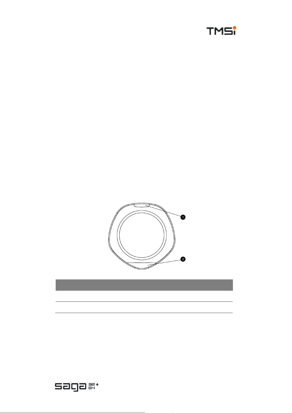
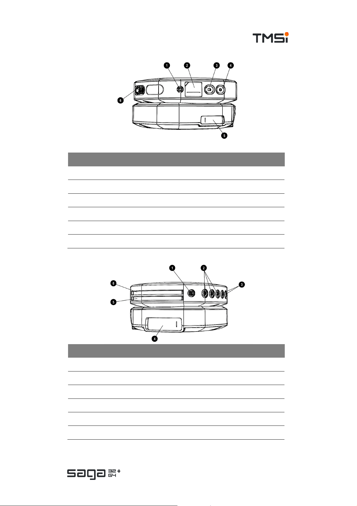
Top View
# Description
1. Event mar k er button
2. Status indicator window
Page 10 of 47
Page 11
USER MANUAL SAGA
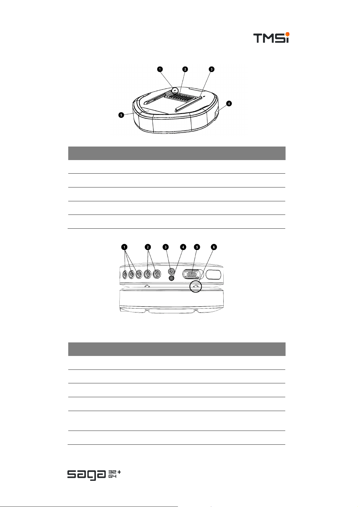
# Description
1. Arrow indicating direction for docking Data Recorder
2. Docking c onnec tor (pins)
3. D ocking rails to guide and secure Data Recorder to the Docking Station
4. Fiber connector (behind c over)
5. Status indicator window
Front View
# Marking Description
1. AUX 1-3 Auxiliary input conn ectors
2. BI P 1,2 – 3,4 Bipolar input connectors
3. GND Patient Ground connector
4. REF Common Referenc e input conn ec tor
UNI 1-32
5.
/ UNI 33-64
6 Docking rails to guide and secure Data Recorder to the D ocking Station
Multi-connector (UN I 1-32) and/or (33-64)
Page 11 of 47
Page 12
USER MANUAL SAGA
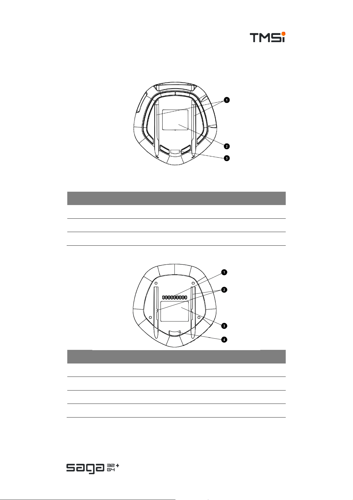
Bottom View
Docking Station
# Description
1. Gutters for docking on the SAGA Bracket
2. Devic e label
3. Dock security ribbon for SAGA Bracket
Data Recorder
# Description
1. Docking con nect or (c ontact points)
2. Gutters for docking on the Docking Station or Bracket
3. Device label
4. Dock security ribbon for SAGA Bracket
Page 12 of 47
Page 13
USER MANUAL SAGA
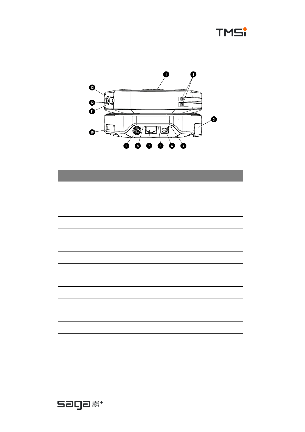
Back view
# Part Description
1. Data Recorder Event marker button
2. Data Recorder Release buttons for battery compartments
3. Docking Station Trigger connec tor (behind cover)
4. Docking Station USB status indicator
5. Docking Station USB connector
6. Docking Station Ethernet status indicator
7. Docking Station Ethernet connector
8. Docking Station P ower status indic ator
9. Docking Station Power c onnector
10. Docking Station Fiber connector (behind c over)
11. Data Recorder ON/OFF button
12. Data Recorder Recording button
13. Data Recorder Fiber connector (behind cover)
Page 13 of 47
Page 14
USER MANUAL SAGA
Side views
# Part Description
1. Data Recorder SYNC OUT c onnec tor
2. Data Recorder Fiber cover
3. Data Recorder Recording button
4. Data Recorder ON/OFF button
5. Docking Station Fiber cover
6. Data Recorder UNI 1-32 multi-connector
# Part Description
1. Data Recorder Digital input c onnector (DIGI)
2. Data Recorder Auxiliary input (AUX 1-3) c onnector s
3. Data Recorder Bipolar input (BI P 1-2 and BIP 3-4) conn ectors
4. Docking Station Trigger connector (behind cover)
5. Data Recorder Compartment f or battery 2
6. Data Recorder Compartment f or battery 1
Page 14 of 47
Page 15
USER MANUAL SAGA
User interface
Data Recorder
Connections
Type Function
Docking connector
Fiber connector
Connects the Data Rec order to the Docking Station for power
supply and data i nt erface
Connects the Data Recorder to the Docking Station for optical
data transmission
Subject connections
Type Unipolar Bipolar Auxiliary
SAGA 32+ 1x 32 unipolar
Patient Ground (GND),
Com mon R ef er enc e (REF)
(multi-conn ector)
SAGA 64+ 2x 32 unipolar
(multi-conn ector)
2x 2 channels
3x 3
channels
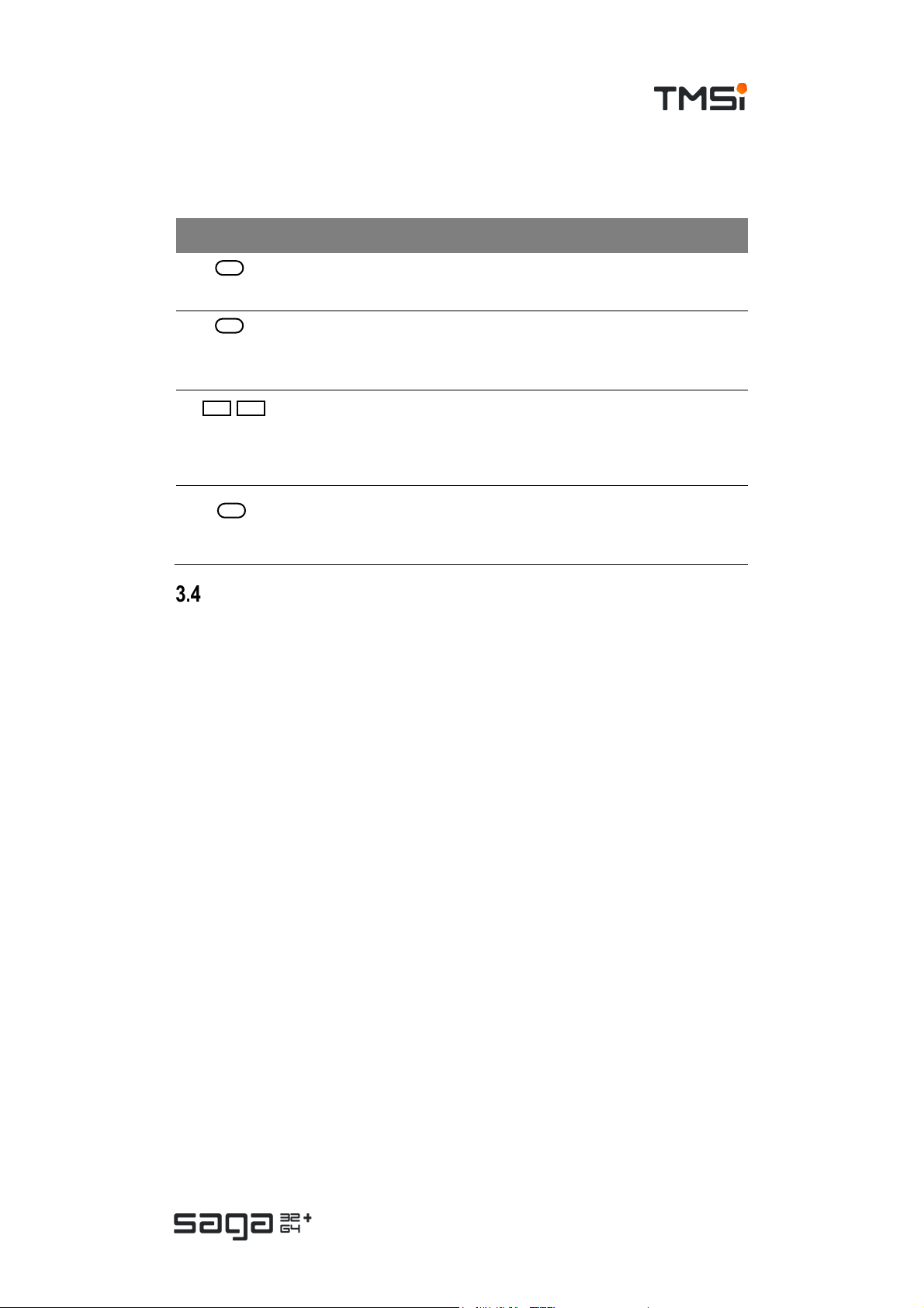
Buttons
Type Function
ON/OFF Switches the devic e on/off if device is not s ampling
Event marker
Recording
Can be pressed by the subject or operator to log a certain time
point or create an event on the sync out port
Starts and stops recording on internal memory if c onfigur ation
allows a manual start/stop of the ambulatory recording
Page 15 of 47
Page 16

USER MANUAL SAGA
Status Indicators
Indicator Function and states
• OFF: Average Ref erence mode
• GREEN (solid): Common Referenc e mode
Reference Mode
Wired
Connection
• ORANGE (solid): Common Reference not available
• ORANGE (blinking): Common Ref er ence disconn ected after s tart
recording, device switched to Average Reference mode.
• OFF: not using fiber connection
• GREEN (solid): Connection with Docking Station via fiber
•
Wireless
Connection
Card Recording
Signal Mode
Battery State
• OFF: Wi-Fi disabled / not looking for Docking Station
• GREEN (solid): Wireless connection, no data transmission
• BLUE (blinking): No Wi-Fi Link, looking for D ocking Station
• ORANGE (blinking): Wireless connection lost
• OFF: there is no (valid) card recording configuration present/active
• GREEN (solid): Card recording configuration loaded; idle
• GREEN (blinking): Card recording active
• BLUE (solid): Card in Configuration / Read-out mode; idle
• BLUE (blinking): W riting C onfiguration / Downloading data
• ORANGE (solid) : Card error (full, no r epair mode possible)
• ORANGE (blinking): Card almost full
• OFF: Data Recorder is of f
• GREEN (solid): Device is in Signal mode
• GREEN (blinking): Signal data transmission active
• BLUE (solid): Device is in Impedanc e mode
• BLUE (blinking): Impedance data transmission active
• GREEN/BLUE (blinking): Device is booting
• OFF: Battery is not charging
• GREEN (solid): Battery fully charged
• BLUE (solid): B atter y charging
• ORANGE (solid): Battery error
• ORANGE (blinking): Battery low
Page 16 of 47
Page 17

USER MANUAL SAGA
Docking Station
Connections
Type Function
USB connector Primary data interf ac e t o PC
Ethernet
connector
Trigger
connector
Fiber connector Connector f or an optical f iber f or data interface with a Data Recorder
Power connector Supply power from Mains adapter to D oc king Station
Docking
connector
Secondary data interface to PC
16-bit trigger input to acquire signals from external equipment.
*NOTE: The 16-bit trigger interf ace is not available on all SAGA dev ices
Con nect or to doc k Data Recorder to Docking Station for power supply and
data interface
Status indicators
Indicator Function and state
Power
Wireless
Connection
Remote Interface*
• OFF: Docking Station is off or booting
• GREEN (solid): Docking Station is ready
• OFF: there is no wireless connection
• GREEN (solid): Wi-Fi connection, no data transmission
• GREEN (blinking): Active data tr ansmission over Wi-Fi
connection
• BLUE (blinking): looking for Data R ecorder
• OFF: monitoring interf ace not available (locked)
• GREEN (solid): Monitor interface on/available
• GREEN (blinking): Monitoring interface active – data exchange
*NOTE: The remote interfac e is not available on all SAGA devices
Page 17 of 47
Page 18
USER MANUAL SAGA
Lights
The lights on the backside of the Docking Station can hav e the following states.
Lights Function
• OFF: Docking Station is off
Power
Ethernet
• GREEN (solid): Docking Station is switched on
• OFF: there is no ethernet connection present
• GREEN (solid): ethernet connection present; idle
• GREEN (blinking): ethernet connection active
Ethernet
(Connector
lights)
USB
• OFF: there is no cable connected
• GREEN: Link detected
• ORANGE (blinking): Data transmission active
• OFF: there is no USB connection present
• GREEN (solid): USB connection present; idle
• GREEN (blinking): USB connection active
Connections
Patient Ground input
The Patient Ground must be connected to keep the amplifier in range. The Patient
Ground connection can be made using a separate lead connected to the GND input.
For some accessories, the Patient Ground connection is also available in the UNI 132 multi-connector. Consult the instructions for use of your accessories to check this.
If this is the case, it is not required to connect the Patient Ground lead to the GND
input of the amplifier.
Common Reference input
The Common Reference input (REF) is optional to use. This input is also available
in the UNI 1-32 multi-connector. Electrode placement is up to the user and depends
on the type of measurement. If Common Reference mode is configured, all unipolar
inputs are referred to this input.
In case during the measurement this electrode becomes detached, the amplifier will
continue as Average Reference amplifier to keep the recording going. This switch of
the reference mode can be disabled in software. The switch from reference mode
will be also logged as an event trigger in the digital channel.
Unipolar multi-connector inputs
The unipolar multi-connector includes 32 unipolar channels to connect for example
an EEG head cap, HDEMG cable, SAGA Break-Out-Box or other accessories. The
SAGA Data Recorder has one or two unipolar multi-connectors, depending on the
configuration.
Page 18 of 47
Page 19

USER MANUAL SAGA
Bipolar inputs
The bipolar input is used for electrophysiological measurements such as EMG, ECG
and EOG. Bipolar inputs are characterized by a pair of electrodes for a + and a –
input signal, the difference of which is recorded. The device supports up to 4 bipolar
channels, accessible via two bipolar input connectors with two bipolar channels
each. An electrode lead may have one pair of electrodes or two pairs of electrodes.
Each bipolar electrode lead plug can contain an identification that can be read out
by the application software.
Auxiliary inputs
The auxiliary inputs are to be used for connecting sensors, particularly those that
contain transducers, to SAGA. The device supports 9 auxiliary channels, which are
divided over three input connectors. Sensors that have multiple functions and/or
transducers, such as the 3D accelerometer will use the three sub-channels of an
AUX input.
An AUX sensor may contain an identification feature that can be read out by the
application software. The application software can use this identification data to
convert the data of the sensor into the correct unit.
Digital input
The digital input DIGI is an input for connecting an event trigger cable or digital serial
sensors, f or example a NONIN digital saturation sensor.
Internal 3D accelerometer
The Data Recorder contains an internal
3D accelerometer that can track the
acceleration in three dimensions and the
orientation of the Data Recorder.
The figure shows how the orientation of the 3D
accelerometer inside the device is. When the
device is worn on the body, it is designed such
that the z-direction points downwards.
Synchronisation Output
The synchronization output can be used to synchronize external devices, application
software or other devices of the SAGA family. The synchronization output is
available on the Data Recorder (SYNC OUT).
By default, the SYNC OUT is configured in ‘Event Marker’ mode, meaning that a
synchronization pulse is sent out upon pressing the Event marker button. One can
configure the SYNC OUT to be a clocked pulse via the application software. The
SYNC OUT port requires a special cable which can be ordered via
sales@tmsi.com.
Page 19 of 47
Page 20

USER MANUAL SAGA
Device labels
Data Recorder
The device label can be found on the
bottom of the Data Recorder. It contains
general product information, in light text on
black background and device specific
information, black text on light background,
such as Serial Number (next to SN),
Reference number (next to REF) and
device type (next to TYPE). Please note
that the depicted device specific
information is an impression of the actual
information that is found on the label. The Type (next to TYPE) describes the exact
version of Data Recorder, such as the number of channels (32+ or 64+ and other
possible variation (different gain or otherwise).
The device label also contains general product information. Please consult 2.1 for
information about the meaning of all mentioned symbols.
Docking Station
The device label can be found on the
bottom of the Docking Station. It contains
general product information , in light text on
black background and device specific
information, in black text on light
background,such as Serial Number (next to
SN) and Reference number (next to REF).
Please note that the depicted device
specific information is an impression of the
actual information that is found on the label.
The device label also contains general product information. Please consult 2.1 for
information about the meaning of all mentioned symbols.
Spare parts – order information
Spare parts that can be ordered separately:
• Suitcase.
• Replacement batteries.
• External battery chargers for SAGA batteries.
• Mains Power supply.
• Optical fibers in various lengths up to 20 metres.
• Trigger cable.
• Synchronisation out cable.
• SAGA Bracket and straps.
• Subject accessories such as Break-Out-Boxes, EEG caps, electrode leads
and AUX Sensors. See
www.tmsi.com for more details.
Page 20 of 47
Page 21

USER MANUAL SAGA
4 INSTRUCTIONS FOR USE
Power the Docking Station
Plug the mains power plug into a well-earthed mains socket and connect the power
adapter connector to the Docking Station. Make sure you use the correct orientation.
When you insert the connector, you will hear a ‘click’. Once connected to mains, the
Docking Station automatically powers up, indicated by the power light on the back
and after a start-up period, the power indicator in the status indicator window signals
that the Docking Station is fully operational.
The Docking Station can be powered down by unplugging the mains power
connector.
Power the Data Recorder
The Data Recorder is either powered by batteries or by m ains via the Docking
Station. The latter only when the Data Recorder is docked on the Docking Station.
Insert or remove batteries
Batteries can be exchanged by opening the battery compartments:
1. Press the orange release button (see 1 in figure below).
2. The compartment door will open enough to grab it with a finger; now you
can pull it open (see 2 in figure below).
3. Slide in the battery, with battery contacts first and oriented to the left.
For further instructions, refer to the Quick Guide in the inlet of the suitcase.
4. Close the battery compartment door, until you hear and feel that it locks.
Briefly press the On/Off button to power on the Data Recorder. When the
device is not acquiring data, the ON/OFF button also powers down the Data
Recorder. During a measurement, the Data Recorder will not power down
by means of the ON/OFF button.
Page 21 of 47
Page 22

USER MANUAL SAGA
Battery change during measurement
Batteries can be exchanged during measurement. Please note that to continue the
recording without interruption, there should always be at least one -sufficiently
charged- battery inserted while exchanging batteries.
Battery low indication
When the battery charge is lower than a certain level, the battery indicator in the
status indicator window starts to blink orange. This indicates that it is time to swap
the battery.
The batteries of the Data Recorder are charged via the Docking Station, when the
Data Recorder is docked onto it or by using the external Battery Charger (see
accessories and add-ons).
Battery discharge
Batteries are discharged on an ‘equal level’ base. This means that if you insert two
batteries, they are being discharged at the same speed. In case there are two
batteries with unequal charge, it will be discharged until they reach the same level.
A battery low indication will therefore always apply to both batteries.
Operation time
The operation time when not on the docking station of the Data Recorder is
approximately 10 hours (two fully charged batteries). The operation time on batteries
is dependent on the device configuration (sampling rate, number of channels, power
consumption of sensors etc.). The operation time does not include scenarios where
batteries are exchanged, or recharged, during measurement (see above).
Charge batteries
Batteries can be (re-)charged via the Docking Station, or using an external battery
charger.
Via Docking Station
The batteries of the Data Recorder are automatically charged whenever it is docked
on the Docking Station.
External battery charger
Remove the battery from the Data Recorder and use the external battery charger as
described in the Instructions for Use of the external charger.
Storage and empty batteries
To prevent draining the batteries, it is recommended to remove the batteries from
the device when you store it for a period longer than a week. If you do not remove
the batteries from the device, make sure a sufficient charge remains in the device as
it may be drained completely.
Docking mechanism
Establish an electrical connection between Data Recorder and Docking Station by
sliding the Data Recorder in the Docking Station. Align the docking rail of the Docking
Page 22 of 47
Page 23

USER MANUAL SAGA
Station and the gutters on the bottom of the Data Recorder. See illustrations below.
The wired connection indicator in the status indicator windows will light up green
when the connection is made correctly.
1. The arrows on the Docking Station indicate the direction for docking the Data
Recorder and the alignment point for the docking rail of the Docking Station.
2. Make sure the Data Recorder is aligned properly and slide it gently onto the
Docking Station.
3. Push forward until the Docking Station and Data Recorder are perfectly
aligned on top of each other and you cannot push any further.
You may dock the Data Recorder on the Docking Station while recording. This may
cause artefacts in the signals. In order to minimize artefacts, gently slide the Data
Recorder on the Docking Station.
To undock the Data Recorder from the Docking Station, push the Data Recorder in
the opposite direction. Depending on the device configuration a Wi-Fi connection will
be established. If you did not configure the device for wireless operation, the
connection between Data Recorder and Docking Station is now interrupted.
Connect accessories
The connectors for subject accessories, except the Patient Ground and Common
Reference described in this section are all provided with a ‘Push-Pull’ mechanism,
to prevent them from getting detached inadvertently. This means that each
connector plug is provided with a sleeve part that slides a bit along the axis of the
plug to operate a retention mechanism. To make a connection, observe the
alignment symbols and gently push the plug into the receptacle of the SAGA device.
To disconnect, take hold of the plug at its moving sleeve, the part closest to the
socket, and gently pull the plug out. Do NOT pull at the accessory wire or at the wire
end of the plug.
Page 23 of 47
Page 24

USER MANUAL SAGA
NOTE
Connect accessory to multi-connector
The multi-connector inputs are labelled with ‘UNI’. Connect the connector of the
accessory to the correct input. Both the connector and the input on the Data
Recorder have a dot on them. Align the red marking on the multi-connector with the
orange dot adjacent to the multi-connector input of the Data Recorder. The UNI 132 and UNI 33-64 connector are to be placed in each other’s opposite, e.g. the part
where the cables exit the connector face towards each other.
Connect bipolar electrodes
The bipolar inputs are marked with BIP. The connector of the accessory is white.
The corresponding receptacles on the Data Recorder are surrounded by a white ring.
Align the orange dot on the enclosure with the arrow on the bipolar connector. Do
not use excessive force to insert the connector. This may damage both Data
Recorder and accessory.
Connect auxiliary sensors
The auxiliary inputs are marked with ‘AUX’. The connector of the accessory is black.
The corresponding receptacles on the Data Recorder are surrounded by a black ring.
Align the arrow with the orange dot above the input on the Data Recorder. Do not
use excessive force to insert the connector. This may damage both Data Recorder
and accessory.
Connect digital sensor
The input for a digital sensor is marked with ‘DIGI’. The connector of the accessory
is nickel. Align the arrow with the orange dot above the input on the Data Recorder.
Do not use excessive force to insert the connector. This may damage both Data
Recorder and accessory.
Data connections
Refer to chapter 9 for used protocols, requirements and settings as applicable.
# Description
1. SAGA (Docking Station)
2. Data acquisition PC
Dat a conn ecti on of preferenc e:
3.
USB or Ethernet
4. Control from PC to SAGA
5. Data from SAGA to PC
In case of connecting SAGA to a LAN network via the ethernet interf ace, it is
recommended to use a secure, non-open network c onnection.
Page 24 of 47
Page 25

USER MANUAL SAGA
The Docking Station of the SAGA system (1) can be connected to a PC (2) v ia a
USB cable and via an Ethernet cable (3). Both connections are used for control of
the device (4) and data transfer to the PC where it can be stored for further
processing (5). It is also used for sending commands from the application software
to the SAGA system to control the device (start/stop, configuration updates etc.).
Software
System requirements
Computer requirements
Support ed Operating
systems
Available ports
Hard drive
• Windows 10 (64 bit)
• Windows 7 SP1 (64 bit)
• USB port (2.0 or higher)
• (Optional) Ethernet port (>100 Mbit)
• 200 GB available (for storage of measurement data)
Driver installation
The latest version of the driver can be downloaded from www.tmsi.com or by using
the USB stick that came with the device. Run the
TMSi SAGA Device Driver Setup x64.exe and follow the steps on screen.
Application Software
TMSi Polybench
TMSi Polybench is software that is commercially available through TMSi. TMSi
Polybench can be used for experimenting with different configurations and customer
specific applications. TMSi Polybench is the framework on which the SAGA Quick
Recording Application was built. TMSi Polybench is software that is intended for
research purposes only and may not be used for diagnosis or treatment.
The Quick Recording Application (QRA) can be used to do recordings with the SAGA
system. The QRA can also be used to configure the SAGA Data Recorder.
TMSi Interface for MATLAB
TMSi has developed an interface to MATLAB (
www.mathworks.com). The interface
can be downloaded free of charge on the TMSi website. TMSi does not sell or
distribute MathWorks products, nor supports them.
Page 25 of 47
Page 26
USER MANUAL SAGA
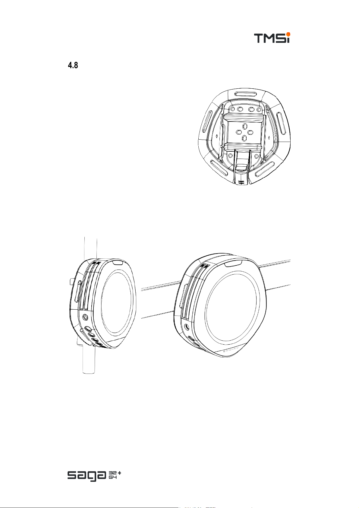
SAGA Bracket
Secure Data Recorder to the subject
It is recommended to use the SAGA Bracket to
secure the Data Recorder to the subject in
setups where the device is carried by the
subject or taken home with the subject.
Secure the bracket to the subject using one of
the configurations described in the instructions
for use of the SAGA Bracket.
The Data Recorder is to be connected to the
bracket by sliding it in from the top until you
hear a ‘CLICK’.
The SAGA Bracket optimizes the carrying
comfort by the subject.
Wall Mount
The SAGA Bracket can also be used to mount the device to a wall, IV pole or
(medical) DIN rail. Please consult the suggested mounting methods in the
instructions for use of the bracket for more details.
Page 26 of 47
Page 27

USER MANUAL SAGA
5 PERFORM A MEASUREMENT
SAGA supports a variety of usage scenarios:
• Streaming data in stationary use (5.1).
• Streaming data in portable setting via wireless connection (5.2).
• Streaming data in portable setting via optical fiber (5.3).
• Ambulatory recording without data streaming (5.4).
Perform Stationary Measurement
The stationary measurement setup consists of a setup where the data acquisition
PC and measurement device are on a fixed place and do not move throughout the
experiment. The Data Recorder is docked in the Docking Station.
Advantages
• Maximum data throughput and signal bandwidth at all channels
(4000/4096 Hz).
• Most reliable data transmission.
• Virtually unlimited recording time.
• System can be mounted to a trolley, (medical) DIN rail.
Disadvantages
• Limited freedom of movement for subject.
Page 27 of 47
Page 28

USER MANUAL SAGA
Perform Portable Measurement using Wireless connection
In the portable measurement setup, the Data Recorder is undocked from the
Docking Station and the Wi-Fi Link is used for data transmission. This setup is
optimal for usage scenarios where freedom of movement is an important
requirement.
The data from the Data Recorder is sent through Wi-Fi to the Docking Station. Please
note that successful wireless data transmission can never be guaranteed, even
when the amount of data (few channels, low sampling rate) is low. If the Docking
Station does not receive a data package, this data is not transmitted again, but
considered to be lost at that moment. Lost data can be recovered using the backup
logging feature on the on-board memory (see below).
Factors that influence wireless transmission are:
• Other wireless networks (or RF devices such as smartphones, tablets), especially
those in the same or adjacent Wi-Fi channels.
• Electrical equipment in the vicinity of the Docking Station and or Data Recorder.
• The line of sight between Docking Station and Data Recorder. Metals and human
beings tend to absorb or reflect a lot of wireless signals.
It is recommended to scan the environment for possible wireless interference
sources.
Pairing of Docking Station and Data Recorder
The Docking Station acts as an access point for the Data Recorder. Once docked,
the Data Recorder and Docking Station will exchange pairing codes automatically.
When you configure the device for wireless use, the connection between Docking
Station and Data Recorder is made.
Data backup logging
During a measurement via a wireless data connection, the Data Recorder will log
the measurement data on the on-board memory card as backup. Lost data can be
retrieved after the measurement has been finished. Refer to chapter 5.6 f or more
detailed instructions on recovery of lost data.
This feature can be disabled in software. Obviously, this will result in a situation
where lost data cannot be recovered.
Page 28 of 47
Page 29

USER MANUAL SAGA
Bandwidth management
A consequence of using wireless data transmission is a limited data transfer
bandwidth. This may require a reduction in the sampling frequency and/or number
of channels that can be recorded. This can be configured to your needs via the
application software.
Perform Portable Measurement using Optical Fiber
The optical fiber can be useful in the following setups:
• If the Wi-Fi link cannot reach the bandwidth that is needed for the
measurement and freedom of movement is an important requirement.
• If the Wi-Fi is not reliable due to interference sources and no other measures
can be taken to improve the measurement environment.
• If backup logging is not a solution because online processing of data is a
primary goal.
The optical fiber is connected to the fiber input on the
Docking Station and Data Recorder after removing the
protective covers on Data Recorder and Docking station.
The rubber covers are marked with the text: ‘fiber’.
Please note the orientation of the fiber connector. The notch must be pointed
downwards. Do not force the fiber connector into the slot.
Perform Ambulatory Measurement
In an ambulatory measurement setup, the Data Recorder is used as a data logger
without the function of data streaming. Typically, this is a user scenario where a
subject is sent home with the Data Recorder for ambulatory monitoring. The data is
logged on the on-board memory and can be downloaded from the on-board memory
afterwards.
Page 29 of 47
Page 30

USER MANUAL SAGA
Measurement Configuration
Configure the ambulatory recording to your needs in the application software. It is
not possible to stream data during ambulatory measurements; all measurement data
is logged on the on-board memory of the Data Recorder.
Start/stop using the Recording button
The button on the Data Recorder marked with an SD Card icon can be used to start
and stop an ambulatory recording. Press and hold the button for 2 seconds to start
recording. Press and hold for 2 seconds again to stop the recording.
Start or Stop recording time
In some user scenarios, the recording should start and/or stop at a specific moment
in time. The start and stop recording times can be configured in
the application software. The time of the Data Recorder is
synchronized to time of the PC when the Data Recorder connects
to a Docking Station that is connected to a PC.
After saving the configuration on the device, the Card Recording
icon will light up green. You may now switch off the device. The
device will start automatically when the start recording time is
reached. When you switch on the Data Recorder before the start
recording time is reached, the start-up sequence will show, after
which the Card Recording icon lights up; after 1 minute the device
goes back to sleep mode until start recording time is reached.
You can always approach the configuration when you dock the Data Recorder on
the Docking Station.
Downloading measurement data from Data Recorder
When the ambulatory recording is finished, the data can be retrieved via the
application software. The recordings are downloaded and stored on the PC for
further analysis. Depending on the configuration and length of the ambulatory
recording, downloading all data may take a while (several minutes to hours). In the
meantime, the system cannot be used for other measurements.
Impedance Measurement
The Data Recorder can be switched to impedance mode. In impedance mode the
user can measure the electrode contact quality of all unipolar channels, including
that of the Patient Ground and Common Reference electrode.
The impedance mode is activated in the application software. The impedance value
ranges from 0 kΩ to 500 kΩ and is an indication of electrode contact quality, where
lower values indicate better electrode contact. If the impedance measurement
indicates 500 kΩ as value, there is no contact between skin and the electrode. If
electrodes do not make good contact effects that may appear are increase of noise,
mains interference (50/60 Hz) or in electrodes that toggle around the edge of
connection/disconnection.
Page 30 of 47
Page 31

USER MANUAL SAGA
Recovery of lost data
In measurement scenarios where data could be lost, for example in a portable set
up over Wi-Fi, the device has a back-up functionality that allows to retrieve lost data
after the measurement session ends.
The Docking Station keeps track of any data that is missed in the status channel.
Data that is missed is marked as ‘Dummy data’. The Data Recorder stores all
measurement data on the on-board memory for the duration of the measurement
session. After the session, ‘Dummy data’ can be replaced by the actual data from
the on-board memory.
A measurement session is ended when the user stops the session by hand or when
the Data Recorder stops recording on memory when the memory is full, or when the
batteries are depleted.
In case the measurement is interrupted because the data acquisition PC or docking
station shuts down because of a major power cut or user error, the Data Recorder
may continue to acquire data on its on-board memory. The recording can then only
be stopped by pressing the Recording button and Event marker button for 4 seconds.
The recorded data can be subsequently downloaded when the Docking Station and
Data Recorder connection is restored.
Because data loss in stationary setups is unlikely, it is not recommended to log all
measurement data on the on-board memory. This will generate large files which are
in many cases useless. In rare cases where external factors such as a power cut or
accidental disconnection of the optical fiber is imminent and data loss is
unacceptable, the operator should take appropriate actions to minimize these
external factors.
Page 31 of 47
Page 32

USER MANUAL SAGA
Status Events
The channel ‘STATUS’ can record several events. These events may be user
triggered or triggered by the device itself. The events are used to provide information
about what happened with the device during recordings. The following status events
are available.
Status Event Origin Bit # Meaning
Marker event User 0 0 = No marker event
1 = Event marker button pressed
Referenc e mode User 1 0 = Average Ref erence mode
1 = Common Reference mode
Referenc e switch D evice 2 0 = No switch event
1 = Automatic switch from Common R eference to Average
Referenc e mode
Average
Referenc e
rem oval
Synchronisation
Out
Dummy data Device 8 0 = Normal measurement data
Ambulatory dat a Device 9 0 = Not downloading ambulatory dat a
Sample data Device 10 0 = Not receiving live data
Bat 1 low Devic e 14 0 = B attery 1 is not low, or not present
Bat 2 low Devic e 15 0 = Battery 2 is not low, or not present
Devic e 3
Devic e 4 0 = Sync-Out is idle
0 = Average removal is enabled
1 = Average removal is dis abled
1 = Sync-Out is active
1 = Dummy data r eceived instead of measurement data.
1 = Downloading previously acquired ambulatory data
1 = Receiving live data stream
1 = Batt ery 1 is low (needs replacement)
1 = Batt ery 2 is low (needs replacement)
Event marker Button
The Event marker button on the device (marked
SAGA 32+ or SAGA 64+ depending on the
device type) can be used to set a marker event
in the STATUS channel. This marker event is
sampled synchronously to the other data.
Pressing this button also creates a trigger on the
synchronisation output of the device, this is a
configuration option in the application software.
Typical use of this button is to mark a specific event during an ambulatory
measurement, so this event can be looked up afterwards.
Page 32 of 47
Page 33

USER MANUAL SAGA
Reference Mode/Switch
The Reference Mode event is set by the user in the application software. It shows if
the data is recorded using the Average Reference or Common Reference input. See
6.3 for more information about using reference modes.
When the reference electrode loses contact to the REF input, the amplifier switches
back to Average Reference mode within a few samples, marked in the Reference
switch bit. If the reference channel comes back in range, the reference mode will
NOT switch back again. This prevents data to be unusable in case the reference
electrode becomes detached, but still makes contact to the skin. This could lead to
switching references throughout the total recording, which is undesirable.
During post-processing of the data, it is important to always monitor the Reference
Mode event, as it directly influences the measurement reference.
Trigger inputs
The digital input of the Data Recorder (marked DIGI) can be used to record a event
trigger from an external source. The digital input is an isolated input so a TTL level
signal can be used to mark specific timepoints. The trigger is sample synchronous
to all the other data.
Battery low
The Data Recorder runs on one or two batteries. In case two batteries are used, they
are drained on an ‘equal level’ basis. This means that the battery with the highest
charge level is drained until they reach an equal level (in case of using batteries with
unequal battery charge levels).
When the battery charge becomes low, the Data Recorder logs an event, marking
which of the batteries is low. One or both batteries should be replaced or recharged.
When the batteries are empty, the Data Recorder logs a ‘battery empty’ event. The
Data Recorder will close any running data acquisition session and power down.
Page 33 of 47
Page 34

USER MANUAL SAGA
6 OPERATIONAL PRINCIPLES
SAGA Device
SAGA is an amplifier for electrophysiological measurements designed for optimal
signal quality. The SAGA amplifier is characterized by low input noise, high input
impedance and high common mode rejection. It is a true DC reference amplifier with
high resolution and uses active signal shielding to minimize electrode cable
capacitance and thereby minimizes cable movement artefacts and sensitivity to
mains interference (50/60 Hz).
The SAGA Device consists of a Data Recorder and Docking Station. The Data
Recorder’s main function is to capture and digitize electrophysiological signals
and/or sensor data. The Docking Station acts as the receiver of the data and relays
it to the data acquisition PC.
SAGA is an all-in-one solution for research applications that can be used as
stationary, portable and ambulatory measurement device.
The unipolar channels of SAGA are configured as an Average Reference amplifier
but can also be configured as a Common Reference amplifier. The device is also
equipped with two dual bipolar inputs for supplementary measurements and three
triple auxiliary inputs to connect sensors and a digital input.
Application software installed on the computer controls the SAGA measurement
functions.
Unipolar input channels
The input stage for measuring unipolar electrophysiological signals is configured as
an Average Reference amplifier. All signals are amplified against the average of all
connected unipolar inputs. Inputs that are not connected to an electrode are
automatically switched off. These channels will show a flat line signal.
Reference
In case the device is configured for Common Reference measurement, the unipolar
inputs are referenced against that electrode. In case the connection of that reference
input is lost, the device will continue on as an Average Reference amplifier.
An Average Reference is recommended to use, as it does not depend on a separate
reference electrode and location of a reference electrode. However, for some
applications the Common Reference configuration could be preferred. This decision
is left to the researcher/clinician.
Active signal shielding
All electrode cables are shielded with the electrode signal itself (active shielding).
The active shielding ensures that disturbances such as cable movement artefacts
and mains interference (50/60 Hz) are reduced to a minimum. No filters that can
cause a significant or frequency dependent behaviour within the analogue bandwidth
are present in the device. There are no notch filters built into the device.
Page 34 of 47
Page 35

USER MANUAL SAGA
Bipolar input channels
The bipolar inputs of SAGA are designed to measure electrophysiological
parameters such as ECG, EMG or EOG, using two electrode connections per bipolar
input. The inputs are configured as a differential amplifier with as output the potential
difference between the two electrodes. Also, here, the amplifier is characterized by
low noise, high common mode rejection and high resolution.
Each input is shielded with the mean of the two input signals. When one of the inputs
falls of, the channel goes in overflow and will show a flat line signal.
Auxiliary input channels
The auxiliary inputs of SAGA are designed to measure physiological parameters that
(may) require a transducer, such as pressure, angle, acceleration, temperature or
skin conductance. The auxiliary inputs are configured as amplifiers with wide input
voltage range to capture the output voltage of the transducers incorporated into
sensor accessories. Additionally, the connectors contain power supply, for
transducers that require electric energy for their operation.
Each auxiliary input connector contains three such amplifiers to accept sensor
accessories with up to three separate transducers, or e.g. a single 3Daccelerometer. Each connector also contains a sensor identification feature. After
plugging the connector into the SAGA Data Recorder, sensor identification data, and
where appropriate transducer conversion information and calibration data is read out
and made available to the application software. Please refer to the datasheet of your
sensor to see what data is provided to the software.
Tips for obtaining optimal quality data
Placement of device
Mains interference (50/60 Hz) is coming from external sources. This can be many
things. It is a common mistake to state that battery powered devices are not
susceptible to mains interference and devices powered from mains are. Mains
interference can get into your measurement system via multiple ways, for example
if you place your device on a metal table with other electrical equipment on it.
Optimal placement of systems will increase the quality of the acquired data. The
ideal measurement setup is on a non-conducting (wood) or well-earthed table. Mains
cables and power adapters should be placed on the floor or at least not on the same
table as the measurement system.
Patient Ground connection
From all electrodes that are connected for a measurement, the Patient Ground
electrode is the most important one. TMSi recommends to use a (wetted) wristband,
or to clean/prepare the skin as good as possible for optimal skin contact to e.g.
electrode patches. Higher Patient Ground electrode impedance may cause more
mains interference in all of the measurement electrodes.
Page 35 of 47
Page 36

USER MANUAL SAGA
Electrode materials
SAGA is a DC-coupled amplifier with a high input range of +/-150 mV. This is more
than sufficient for common measurement setups. The electrode-skin interface will
act as a battery which causes a DC-shift in the signal of several millivolts up to a few
hundred. If all electrodes, including Patient Ground, are made of the same material,
this will not be a problem at all. If materials are mixed (for example gold electrodes
or platinum electrodes are used in combination with Ag/AgCl electrodes, the DC shift
can cause that channels go out of range of the amplifier.
Different electrode materials have different DC characteristics. Some materials may
drift a lot, whereas others are fairly stable over time. Ag/AgCl is known to be a very
DC-stable material and is used in most of the commercially available electrodes for
contacting intact skin.
SAGA is also available in other configurations with a higher input range (up to +/600 mV) which allows the use of different materials without saturations. Contact
sales@tmsi.com for information about the availability of these configurations.
Electrode movement artefacts
When cables pull on the electrode, this is visible in the data as a DC-shift, because
of the change in electrode-skin interface. This can be prevented by making a strain
relief loop in the cabling. If for some reason the cable is pulled, the strain relief
prevents that the cable also pulls on the electrode, causing artefacts. Cable
movement in itself is not a problem thanks to SAGA’s active shielding technology.
Rereferencing/Artefacts
If during a measurement an electrode is causing artefacts in the data it may be
necessary to exclude this electrode from the measurement data. SAGA measures
its signals against the average of all connected electrodes. This means that if an
electrode becomes disconnected, this electrode is immediately taken out of the
average calculation. If a channel needs to be excluded from the measurement
ensemble, follow the steps below:
1. Identify the channels that are to be excluded from the measurement
ensemble.
2. In the measurement data processing create a new signal by taking the
average of all electrodes except those that are to be excluded.
3. Subtract the values of (2) from each electrode.
These steps are called rereferencing: a recalculation of the reference signal.
Page 36 of 47
Page 37

USER MANUAL SAGA
Environmental protection
7 MAINTENANCE
Servicing and Updates
The product does not contain user serviceable parts. Maintenance is limited to
cleaning at user discretion. Repairs can only be performed by the manufacturer,
contact
staff will determine whether a repair is required and possible.
The product does not require regular servicing or re-calibration during its expected
service life.
Bug fixes or improvements to the firmware may become available for download from
the website (
instructions accompanied with the update package carefully. Not complying with
these instructions may cause the device to become unusable.
support@tmsi.com in case the product needs to be repaired. TMSi Support
www.tmsi.com). This update can be performed by the user. Follow the
Cleaning instructions
• Before cleaning, make sure the product is switched off and not in contact with a subject.
• Use only tap water, if necessary with a mild detergent, applied through a soft damp cloth.
• Do not spill fluids or submerge the product in liquids.
• Do n ot use sharp tools or aggressive chemicals for cleaning or disinfecting.
• The product can be disinf ected using Incidin Plus® if necessary. Other disinfectants may
damage the product.
• Do not sterilize the product.
Disposal instructions
Special EU instructions for disposal are applicable to a product on which this symbol is
placed. These instructions apply to all parts of the product.
When the product has reached End of Life, it must not be dispos ed of with other waste.
Instead, it is t he us er’s responsibility to dispose of their waste equipment by handing it
over to a designated collection point for the recycling of waste electrical and electronic
equipment.
The separate collection and recycling of your waste equipment at the time of disposal
will help to c onserve natur al resources and ensure that it is recycled in a manner that
protects human health and the environment.
For more information about where you can dispose of your waste equipment for
recycling, pleas e contact your local city office, your household waste disposal service,
or TMSi.
Page 37 of 47
Page 38

USER MANUAL SAGA
8 ELECTROMAGNETIC GUIDANCE
Degradation of performance
Electromagnetic disturbances, such as electrostatic discharge, mains supply
overvoltage spikes and mains interruptions may cause the following types of
degradation of performance:
• Noticeable artefacts on signals. These should be discarded because they
are clearly non-physiological signal traits.
• Transient interruptions of signal data communication; in extrem e cases,
cessation of data communication. Data does not appear on screen, but
signal acquisition continues and signal data is recorded as indicated by the
blinking green Card Recording indicator on the Data Recorder. The product
has a provision for repairing data lost in communication. Refer to
for data repair.
• As a result, the SAGA product may need to be restarted (recycle power).
Basic safety is not affected by these phenomena, and the effect on essential
performance can be mitigated by user actions.
To prevent electrostatic discharges relocate the measurement to an environment
with anti-static floor and furniture and/or do not unnecessarily touch product parts.
To prevent mains interruptions use an uninterruptible (mains) power supply. Further
guidance can be found in the tables on the following pages.
chapter 5.6
Portable and mobile RF communications equipment can affect the performance of
the SAGA product by:
• Disturbing data communication within the system. This may cause loss of
measurement data for real-time processing or display on the PC. But the
signal data can be repaired as described in
• Increasing noise level on signals, large offset shifts or causing signal
distortion in extreme cases.
Basic safety is not affected by these phenomena, and the effect on essential
performance can be mitigated by user actions.
To prevent their interference, keep portable and mobile RF communications
equipment at sufficient distance from the product.
The product needs special precautions regarding EMC and must be installed and
put into service according to the EMC information outlined on the next pages.
Note that the SAGA Docking Station is intended to be used only in professional
healthcare environments. The SAGA Data Recorder may also be used in domestic
areas.
chapter 5.6.
Page 38 of 47
Page 39

USER MANUAL SAGA
Electromagnetic emission
Guidance and manufacturer’s declaration – electromagnetic emissions
The product is intended for use in the electromagnetic environm ent specified below. The customer or the user of the product
should assure that it is used in such an environment.
Emission test Compliance Electromagnetic env ironment – guidance
RF emissions
CISPR 11
Gr oup 1 The product uses RF energy only for its internal
function. Therefore, its RF emissions are very low
and are not likely to cause any interference in nearby
electronic equipment.
RF emissions
CISPR 11
Harmonic emissions
IEC 61000-3-2
Class A
(Docking Station)
Class B
(Data Recorder)
Class A
NOTE The EMISSIONS characteristics of the
Docking Station make it suitable for us e in industrial
areas and hospitals (CISPR 11 class A). If it is used
in a residential environment (f or which CISPR 11
class B is normally required) it might not offer
adequate prot ection to radio-frequency
communic ation services. The user might need to
take mitigation measures, such as relocating or reVoltage fluctuations / flicker
emissions
IEC 61000-3-3
Complies
orienting it.
The Dat a Rec or der is suitable for use in all
establis hments, including domestic establishments
and those directly connected to the public low-
voltage power supply network that supplies buildings
used for domestic pur poses.
Electromagnetic immunity
Guidance and manufacturer’s declaration – electromagnetic immunity
The product is intended for use in the electromagnetic environm ent specified below. The customer or the user of the product should
assure that it is used in such an environment.
Immunity test IEC 606 01-1-2 test level Complian
Electrostatic
discharge
(ESD)
IEC 61000-4-2
Radiated RF
EM fields
IEC 61000-4-3
±8 kV
contact
±15 kV
air
10 V/m
(80 to 2700) MHz
80 % AM at 1 kHz
ce level
±8 kV
±15 kV
10 V/m Degradation of performance may occur: Electromagnetic
Electromagnetic env ironment – guidance
Degradation of performance may occur: Electrostatic
discharges may result in air sparks at connectors coincident
with signal loss. Sometimes a measurement restart is required.
For further information refer to chapter 8.1.
Floors shoul d be wood, concrete, or ceramic tile. If floors are
covered with synthetic material, the relative humidity should be
at least 30 %.
radiation may distort and disturb acquired signals. At some
frequencies the live communication link may be interrupted.
For further information refer to chapter 8.1.
Page 39 of 47
Page 40

USER MANUAL SAGA
Guidance and manufacturer’s declaration – electromagnetic immunity
The product is intended for use in the electromagnetic environm ent specified below. The customer or the user of the product should
assure that it is used in such an environment.
Immunity test IEC 606 01-1-2 test level Complian
Proximity fields
from RF
wireless
communication
s equipment
IEC 61000-4-3
27 V/m
At 385 MHz, 1.8 W ,
18 Hz pulse modulation
28 V/m
At 450 MHz, 2 W,
1 kHz sine FM modulation with
±5 kHz deviation
9 V/m
At 710 MHz, 745 MHz and
780 MHz, 0.2 W,
217 Hz pulse modulation
28 V/m
At 810 MHz, 870 MHz and
930 MHz, 2 W,
18 Hz pulse modulation
28 V/m
At 1720 MHz, 1845 MHz and
1970 MHz, 2 W,
217 Hz pulse modulation
28 V/m
At 2450 MH z, 2 W ,
217 Hz pulse modulation
9 V/m
At 5240 MHz, 5500 MHz and
5785 MHz, 0.2 W,
217 Hz pulse modulation
ce level
27 V/m
28 V/m
9 V/m
28 V/m
28 V/m
28 V/m
9 V/m
Electromagnetic env ironment – guidance
Degradation of performance may occur: Electromagnetic
radiation may distort and disturb acquired signals. At some
frequencies the live communication link may be interrupted.
For further information refer to chapter 8.1.
Portable and mobile RF comm unications equipment should be
used no closer to any part of the product, including cables,
than 0.3 m.
Electrical fast
transients /
burst
IEC 61000-4-4
Surges
IEC 61000-4-5
Conducted
disturbances
induced by RF
fields
IEC 61000-4-6
Rated power
frequency
magnetic fields
IEC 61000-4-8
±2 kV
100 kHz repetition frequency
for power suppl y lines
±1 kV
for input/output lines
±1 kV
Line-to-line
±2 kV
Line-to-ground
3 V 1
(0.15 to 80) MHz
80 % AM at 1 kHz
1
6 V
in ISM and amateur radio
bands within (0.15 to 8 0) MH z
80 % AM at 1 kHz
30 A/m
50 Hz or 60 Hz
±2 kV
±1 kV
±1 kV
±2 kV
3 V
6 V
N.A.
5
Degradation of performance may occur: Electrical transient
pulses on AC mains and USB connection may cause signal
loss and require a measurem ent restart in wireless operation.
In docked operation transient signal interruptions during pulses
may occur. For further information refer to chapter 8.1.
Mains power quality should be that of a typical commercial or
hospital environment.
Degradation of performance may occur: During surges
transient signal interruptions may occur. For further information
refer to chapter 8.1.
Mains power quality should be that of a typical commercial or
hospital environment.
Degradation of performance may occur: High level conducted
disturbances on AC mains may cause data communication
loss, on other connections including subject connections they
may cause transient signal interruptions. For further
information refer to chapter 8.1.
The product is not intended for environments with restricted
access due to strong magnetic fields.
Page 40 of 47
Page 41

USER MANUAL SAGA
6. Applies only to devic es intended to be powered from 12/24 V road vehicle power systems.
Guidance and manufacturer’s declaration – electromagnetic immunity
The product is intended for use in the electromagnetic environm ent specified below. The customer or the user of the product should
assure that it is used in such an environment.
Immunity test IEC 606 01-1-2 test level Complian
Electromagnetic env ironment – guidance
ce level
Voltage dips
IEC 61000-411
Voltage
interruptions
IEC 61000-411
2
0 % U
; ½ cycle
T
At 0°, 45°, 90°, 135°, 180°,
225°, 270° and 315°
2
0 % U
; 1 cycle
T
and
2
70 % U
; 25/30 3 cycl es
T
Single phase: at 0°
2
0 % U
; 250/300 3 cycl es 0 % UT Degradation of performance may occur: Interruption of AC
T
0 % U
0 % U
Mains power quality should be that of a typical commercial or
T
hospital environment.
T
mains may require measurement restart. For further
information refer to chapter 8.1.
If the user of the product requires continued operation during
power mains interruptions, it is recommended that t he product
be powered from an uninterruptible power supply or a battery.
Electrical
As specified in ISO 7637-2 N.A. 6
transient
conduction
along supply
lines
ISO 7637-2
Notes:
1. This is the R.M.S. level, before modul ation is applied.
2. U
3. E.g. 10/12 means 10 p eriods at 50 H z or 12 periods at 60 Hz.
5. Applies only to d evic es with magnetically sensitive components or circuitry.
is the A.C. mains voltage prior to appl ication of the test level.
T
Page 41 of 47
Page 42

USER MANUAL SAGA
9 TECHNICAL SPECIFICATIONS
Use the REF number on the device label to identify the device configuration.
General Specifications
Type SAGA 32+ 32 unipolar, 4 bipolar, 9 auxiliary, 1 digital
SAGA 64+ 64 unipolar, 4 bipolar, 9 auxiliary, 1 digital
REF
Size (device only) D ata Recorder: ᴓ 179 mm, height: 41 mm
Weight Data Recorder: 0.7 kg (excluding batteries)
Power consumption
Supported Sampling Rates
(Hz)
On-board storage
See devic e label
Docking Station: ᴓ 179 mm, height: 47 mm
Docking Station: 0.7 kg
Data Recorder:
Docking Station: 5 W to 25 W
Base Rate: 4096 Hz 4096 / 2048 / 1024 / 512 / 256
Base Rate: 4096 Hz 4000 / 2000 / 1000 / 500 / 250
32 GB, non-removable
<5 W on battery power
<10 W when docked, charging
Regulatory Specifications
Power source External mains power supply and/or internal batteries
Mode of operation Continuous operation
Electric shock
protection
Applied parts Ref er to chapter 3.2.
Mains power supply: Class I
Applied parts: Type CF
Accessib le parts Refer t o chapter 3.2.
Ingress protection IP22 (Data Recorder)
Protection against particulate matter with ≥12,5 mm diameter and against
ingress of dripping water when 15° tilted
Mains power supply
Brand, type SLpower, ME30B1548F02
For further inf ormation, including specific ation, refer to documentation
and label of the mains power supply. (
Page 42 of 47
www.slpower.com )
Page 43

USER MANUAL SAGA
Battery
Batteries
1 or 2 batteries
Power Saving
Battery low indication
level
Battery empty shut
down level
Brand, type RRC power solutions, RRC1130
30 minutes (no connection to PC)
3.3 V
3.1 V
For further information, including specification, refer to Manual and Data Sheet
(www.rrc-ps.com) and label of the batter y.
Communication Data Recorder to Docking Station
Wi-Fi Ban d 2.4 GHz
Range 10 m
Power 16 dBm
Bandwidth Maximum 2 Mb/s
Sec urity WPA2
Fiber Length Up to 20 meter s
Bandwidth Maximum 15 Mb/s
Electrical Bandwidth Maximum 30 Mb/s
Communication Docking Station to PC
USB Standard 2.0
Ethernet Standard LAN, IEEE 802. 3 10/100 Mb/s
Communication Docking Station to Remote Interface
Bluetooth Band 2.4 GHz
Range 10 m
Power 5.8 dBm
Bandwidth Maximum 1 Mb/s
Transportation Conditions
Temperature -20 °C to +60 °C
Humidity 15 % to 90 %, non-c ondensing
Pressure 500 hPa to 1060 hPa
Storage Conditions
Temperature 0 °C to +40 °C
Humidity 15 % to 90 %, non-condensing
Pressure 500 hPa to 1060 hPa
Page 43 of 47
Page 44

USER MANUAL SAGA
Usage Conditions
Temperature Data R ecorder (alone): +5 °C to +40 °C
Docking Station (alone): +5 °C to +30 °C
Docking Station + Data Recorder: +5 °C to +30 °C
Humidity 15 % to 90 %, non-condensing
Pressure 700 hPa to 1060 hPa
Unipolar Channel Specifications
Number of channels
• SAGA 32+: 32
• SAGA 64+: 64
RMS noise
(0.1 to 100) Hz
Input Range
(Differential Mode)
Input Range
(Common Mode)
Resolution < 20 nV
Accuracy 2 % of full scale
Input resistance
Common Mode
Rejection Rati o
Amplifier concept
Shielding Individual signal shielding
Analogue bandwidth DC to 800 Hz at highest sampling rate, 0.35 * sampling rate otherwise
Anti-alias filter 1.6 kHz l ow-pass
<1 µV
-150 mV to +150 mV (@ 0 V common mode)
Input ranges up to +/-600 mV are available upon request
-2 V to +2 V (@ 0 V differential)
>1 GΩ
100 dB (typical) @ 50/60 Hz
• Average Refer ence amplifier, or
• Com mon R ef er enc e am plif ier
(when using Common R eference input)
Impedance Mode Separate mode, including Patient Ground impedance measurement
Range
Accuracy
Res ol ut ion
0 kΩ to 499 kΩ, (500 kΩ means not connected)
10 % of reading + 1 kΩ
1 kΩ
Page 44 of 47
Page 45
USER MANUAL SAGA
Bipolar Channel Specifications
Number of channels 4 (2 x dual channel input)
RMS noise
(0.1 to 100) Hz
Input Range
(Differential Mode)
Input Range
(Common Mode)
Resolution < 20 nV
Accuracy 2 % of full scale
Input resistance
Common Mode
Rejection Rati o
Shielding Average signal shielding
Analogue bandwidth DC to 800 Hz at highest sampling rate, 0.35 * sampling rate otherwise
Anti-alias filter 2.1 kHz l ow-pass
<1 µV
-150 mV to +150 mV (@ 0 V common mode)
-2 V to +2 V (@ 0 V differential mode)
>1 GΩ
100 dB typical
(+ and – inputs are shielded with average of + and – signal.)
Auxiliary Channel Specifications
Number of channels 9 (3 x triple channel input)
Output Voltage +5 V, max 45 mA for all channels together
RMS noise
(0.1 to 100) Hz
Input Range -3 V to +3 V
Resolution < 0.6 µV
Accuracy 2 % of full scale
Input resistance
Analogue bandwidth DC to 800 Hz at highest sampling rate, 0.35 * sampling rate otherwise
Anti-alias filter 2.1 kHz l ow-pass
<20 µV
>0.5 GΩ
Page 45 of 47
Page 46

USER MANUAL SAGA
Channel Overview
Nam e Connection Rem ar ks
CREF REF and UNI 1-32
UNI 1 to
UNI 32
UNI 33 to
UNI 64
BIP 1
BIP 2
BIP 3
BIP 4
AUX 1.1
AUX 1.2
AUX 1.3
AUX 2.1
AUX 2.2
AUX 2.3
AUX 3.1
AUX 3.2
AUX 3.3
PGND GND and UNI 1-32 Only available in impedance mode
DIGI DIGI (with s erial s ensor)
SpO2
PLETH
HRate
Stat
UNI 1-32
UNI 33-64 Only for SAGA 64+
BIP 1 2
BIP 3 4
AUX 1
AUX 2
AUX 3
DIGI (with Saturation sensor)
X-AXIS
Y-AXIS
Z-AXIS
STATUS Internal
COUNTER Internal
TRIGGER DIGI
Internal 3D accelerometer
Page 46 of 47
Page 47

Copyright © 2019 TMSi. All rights reserved.
www.tmsi.com
 Loading...