

Page 1
TM5
Guide Book
Hardware Version: 1.00
Software Version: 1.64
Page 2

ii
Release Date : 2017-10-01
Page 3

iii
The information contained herein is the property of Techman Robot Corporation (hereinafter referred to as the
Corporation). No part of this publication may be reproduced or copied in any way, shape or form without prior
authorization from the Corporation. No information contained herein shall be considered an offer or commitment.
It may be subject to change without notice. This Manual should be reviewed periodically. The Corporation will not
be liable for any error or omission.
and logos are the registered trademark of TECHMAN ROBOT INC. and the company reserves the
ownership of this manual and its copy and its copyrights.
Page 4

iv
I Hardware Installation Manual
1. Safety Information
1.1 Overview
1.2 Validation and Liability
1.3 Limitations on Liability
1.4 Warning and Caution Symbols
1.5 General Safety Warning
1.6 Scope of Use
1.7 Risk Assessment
1.8 Emergency Stop
1.9 Joint Rotation without Drive Power
2. Safety Functions and Interface
2.1 Overview
2.2 Safe Stop Time
2.3 Safety-related Limiting Mechanisms
2.4 Singularity/Singular Point
2.5 Safety Setting
2.5.1 Operating Position
2.6 Operating Mode
2.6.1 Auto Mode
2.6.2 Manual Mode
2.6.2.1 Manual Control Mode
2.6.2.2 Manual Trial Run Mode
2.6.3 Changing the Operating Mode
2.7 Hold to Run
2.8 Collaborative Mode and Safety Zone Setup
2.8.1 Collaborative Mode and Parameter Configuration
2.8.2 Collaborative Space Configuration for Safety
3. Transportation
4. System Hardware
4.1 Overview
4.2 System Overview
4.2.1 Robot Arm
4.2.1.1 Robot Range of Motion
4.2.1.2 Robot Arm Maximum Allowed Payload
4.2.1.3 Robot Arm Installation
4.2.2 Robot End Module
4.2.2.1 End Module Components
4.2.2.2 End Flange Surface
4.2.2.3 End Mounting Caution
4.2.2.4 End Indication Light Ring Table
4.2.3 Control Box
4.2.3.1 Robot Stick
2
2
2
3
4
5
5
6
6
8
9
10
10
14
16
16
16
16
16
16
17
17
18
18
20
26
27
27
27
28
28
32
33
34
34
36
37
37
39
39
Page 5

v
5. Electrical Interface
5.1 Overview
5.2 Electrical Warnings and Cautions
5.3 Control Box
5.3.1 Safety Connector
5.3.2 Power Connector
5.3.3 Digital In/Out
5.3.4 Analog In
5.3.5 Analog Out
5.3.6 EtherCAT: For EtherCAT Slave I/O Expansion
5.3.7 USB Port
5.4 Tool End I/O Interface
5.4.1 I/O Terminals
5.4.2 Connecting Tool End Digital Out
5.4.3 Connecting Tool End Digital In
5.4.4 Connecting Tool End Analog In
5.5 Control Box Interfaces
5.6 Control Box Power Interface and Robot Interface
5.6.1 Control Box Power Interface
5.6.2 Robot Interface
6. Maintenance and Repair
7. Warranty Statement
7.1 Product Warranty
7.2 Disclaimer
Appendix A. Stop Time and Distance
Appendix B. Technical Specifications
42
42
43
43
45
45
47
48
48
48
49
49
51
51
52
52
53
53
54
55
55
56
57
58
Page 6

1
Hardware Installation Manual
I
Hardware Version: 1.00
Software Version: 1.64
Page 7

I Hardware Installation Manual 1. Safety Information2
1. Safety Information
1.1 Overview
This chapter describes important safety information about the Techman Robot. The users and system
integrators of the Techman Robot should carefully read and understand this chapter before using this robot.
1.2 Validation and Liability
The information contained herein neither includes how to design, install, and operate a complete robotic arm
system, nor involves the peripherals which may affect the safety of the complete system. The design and
installation of the complete system must comply with the safety standards and regulations in the country of
use. The integrators of the robot should understand the safety laws and regulations in their countries and
prevent major hazards from occurring in the complete system.
This includes but is not limited to:
• Risk assessment of the whole system;
• Adding other machines and additional safety mechanisms based on the results of the risk assessment;
• Building appropriate safety mechanisms in the software;
• Ensuring the user will not modify any safety-related measures;
• Ensuring all systems are correctly designed and installed;
• Clearly labeling user instructions;
• Clearly marked symbols for installation of the robot arm and the integrator contact details; and
• Collecting all documents into the technology folder, including the risk assessment, and this Manual.
1.3 Limitations on Liability
No safety-related information shall be considered a guarantee by Techman Robot that TM5 will not cause
personnel injury or property damage.
Page 8
3I Hardware Installation Manual 1. Safety Information
Note
Danger
Warning
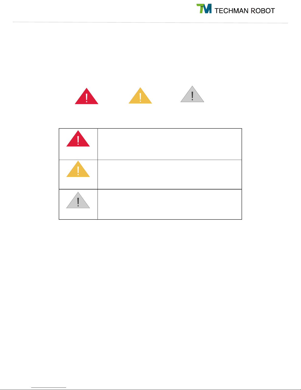
This symbol indicates that failure to observe these instructions will
lead to death or serious injuries.
This symbol indicates that failure to observe these instructions may
lead to injuries.
This symbol indicates that failure to observe these instructions may
lead to equipment damage.
Danger
Warning
Note
1.4 Warning and Caution Symbols
The Table below shows the definitions of the warning and caution levels described in each paragraph of this
Manual. Pay close attention to them when reading each paragraph, and observe them to avoid personal
injuries or equipment damage.
Page 9

I Hardware Installation Manual 1. Safety Information4
1.5 General Safety Warning
The following shows the general warnings and cautions. Note that there may be related warnings and
cautions listed in the remaining sections, in addition to the ones described in this section. Read them
carefully as well.
Danger:
1. Before handling, installation, operating, maintaining and servicing this product, carefully read the
product's specifications and operating manual. Make sure that all conditions meet the requirements of the
specifications and manual to avoid unexpected accidents during use (e.g. improper operation or operating
conditions that exceed the product specifications) that may cause personnel injury or damage to this
product.
2. Before using and installing this product, the installer must perform the necessary risk assessments
based on the conditions of use to avoid serious personal injuries during operation (e.g. Collision between
equipment and personnel) due to improper parameter settings.
Warning:
1. Before using this product, make sure that there is at least 1 or more emergency stop device on the
machine to stop the movement of the robot in case of accidents. Always make sure that the devices are
functioning properly.
2. Prior to assembly and disassembly, or servicing and maintenance of this product, make sure that the
power is disconnected and the rear area is clear before proceeding. Doing so will help prevent injury to
personnel or damage to equipment due to accidental short-circuits or electrocution during use.
3. When operating this product, the operator should not wear loose clothing or other accessories (e.g.
necklaces, ties,and bracelets) to avoid injuries which may happen when said clothes or accessories are
drawn into the machine during operation.
4. In the event of product malfunction, follow the proper procedures and channels to contact qualified
personnel for troubleshooting and repair. To prevent damage to the equipment due to improper disassembly,
the operator is strictly prohibited against attempting to make direct repairs.
5. Before the robot begins operations, make sure that each part is secured in place to prevent any accidents
due to the robot being improperly secured during operation.
6. Before the robot begins operations, always make sure that no personnel or obstacles are within its range
of motion. If the operating environment involves human-machine collaborative work, always perform the
necessary risk assessments before the start of operations.
7. Unauthorized personnel are not allowed to operate this product in order to prevent any possibility of
personal injury or damage to the machine caused by improper operation.
8. Do not install or operate this product in dangerous environments (e.g. in the presence of a strong
magnetic field; dangerous gases; fire, or flammables) to avoid dangers which may occur due to external
conditions during operation.
Page 10

5I Hardware Installation Manual 1. Safety Information
Note:
1. Personnel approaching or operating the robot should check the machine warning lights before proceeding.
2. After editing the task flow, always start operations in Manual Mode to check that all actions can be
performed correctly during operation before switching the operating mode to Auto.
3. Do not turn off power to the machine while it is in motion unless absolutely necessary.
1.6 Scope of Use
The TM Robot is a collaborative robot with a built-in vision system. The dedicated HMI simplifies robot
deployment and increases its operational flexibility, making it suitable able for the production and
manufacturing industries.
The design of the TM Robot focuses on the safety of the human-machine collaboration. However, the
collaborative robot is intended only for the applications for which risk assessment has been conducted
without any hazards identified. The risk assessment involves the robot and the related peripherals as well
as environment.
The risk assessment has been performed for any use or application and no hazard is found. The use of the
robot for any purpose other than the intended is prohibited. The Corporation shall not in any event be liable
for any conditions including, but not limited to, the following:
- Use in a potentially hazardous environment
- Use in any applications that may threaten human lives
- Use in any application that may cause personal injuries
- Use before completion of the risk assessment
- Use for auxiliary support
- Use when the rated performance cannot be reached
- Use when the reaction time of safety functions is insufficient.
- Use with inappropriate parameters for operations
- Applications which may cause damage to the robot itself
1.7 Risk Assessment
Before using and installing this product, the user must perform the necessary risk assessments based on
the conditions of use. Refer to the regulations specified in the documentation, such as ISO-10218-2, ISO-
12100, and ISO-15066 for details. The purpose of the risk assessment is to predict possible accidents
during the operation, and prevent the occurrence of accidents or reduce the severity of injuries effectively
with appropriate protective measures. Therefore, the scope of the risk assessment must include any oper-
ation of the machine. Once a risk assessment has been conducted, the user may use the relevant external
components (e.g. sensors, emergency stop devices, fencing or other barrier devices) and configuration of
safety-related parameters in the operating system to prevent potential accidents during operations. External
safety-related components should be installed as directed. Refer to Chapter 2 for the safety settings of the
operating system and how other safety components should be used.
Page 11

I Hardware Installation Manual 1. Safety Information6
TM Robot expressly indicates that the major significant residual risk below may exist:
1. Excessive rotation of the 6th joint may result in the fingers being caught between the rear-end of the
camera module and the 5th joint module.
2. The palm or fingers may get caught between the end module and the body of the robot during robot
motion or Hand Guide Instruction.
3. Injuries due to collision with the robot.
4. Injuries due to being hit, crushed, or pinched between the robot and a hard surface.
5. Injuries caused by loose screws which are used to fix the robot to the base.
6. TM Robot explicitly states that serious residual risk may exist in the following scenarios: There is a risk
that improper configuration of the collaborative zone or safety space, as well as the running of incorrect
projects, may lead to the robot colliding at full speed with the human body within the collaborative space.
1.8 Emergency Stop
If any accidents occur during the operation of the robot, the user can stop all movement by pressing the
Emergency Stop button. When the robot stops, the user must ensure that all fault conditions are eliminated
before manually turning off the limit switch for the Emergency Stop button and restarting the robot.The
Emergency Stop button is only used in critical conditions, to stop the robot during normal operations please
use the Stop button on the system controller.
Once the risk assessment has been conducted, if an Emergency Stop button needs to be installed then the
selected device must comply with the requirements of ISO-60204-1.
1.9 Joint Rotation without Drive Power
1. When the Emergency Stop Button is triggered during the operation of the robot, the control system will
stop its movement and cease supplying sufficient power to its joint actuators to achieve an effect equivalent
to disconnecting the power for actuation to the robot. In this case, the brake at each joint automatically locks
the joint to prevent each joint of the robot from drooping continuously under gravity. If the robot needs to
be moved to clear the fault condition, press and hold the FREE button on the end module of the robot. Two
seconds later, the braking device at the joint will disengage the brakes. Before releasing the FREE button,
the user can move the machine by pushing the joint to clear the fault condition.
When an emergency button is pressed, the robot system issues a command to stop the robot,
and stops supplying sufficient power to its joint actuators for an effect equivalent to disconnecting
the power for the actuation of the robot. In this case, the braking device at each joint automatically
locks the joint. However, before the brake completely stops the robot, the robotic link will, under
the force of gravity, make the unpowered joint slightly droop in the direction of gravity. In this
case, be aware of the possibility that the robot end module may pinch the body or collide with the
surroundings.
Warning
Page 12

7I Hardware Installation Manual 1. Safety Information
2. If the robot needs to be moved when the power is disconnected (e.g. disengaging packaging posture),
the user can first press the Emergency Stop button while there is no power, then press the Power Button on
the controller to supply power to the system. When the control system is turned on, the light blue indicator
light on the end module will blink. At this time, press the FREE button on the end module to release the
braking device at the joint. The user can move the joint by pushing it.
When overriding the brake during the movement without drive power, note that the robot limb will
droop back down due to the gravity when the FREE button is pressed for 2 seconds. Be sure
to grab the end module securely and prepare for the added weight when you press the FREE
button to unlock the brake. Lift the end module upwards to avoid increasing the severity of injury
if someone is caught under the machine. If the end module can't be held securely or you lack
sufficient strength to prevent the robot arm from lowering, release the FREE button immediately.
Each joint of the robot will be locked again to avoid personal injury or machine damage.
Danger
Page 13
I Hardware Installation Manual 2. Safety Functions and Interface8
2. Safety Functions and Interface
2.1 Overview
The control system of the Techman Robot features a series of built-in safety-related functions, and provides
an interface for connecting with external safety devices.
For human-machine collaborative tasks, the user or system integrator must configure the safety-
related parameters based on the results of the risk assessment. For tasks during which human
and machine are separated, evaluate the selection and configuration of external protection
equipment. Failure to do so may result in personal injuries or death.
For instructions on how to configure the safety-related parameters in the UI, refer to Section 2.5.
For instructions on how to connect external safety devices to the system, refer to Chapter 5.
Note:
1. The user or system integrator should configure the safety-related parameters based on the
results of the risk assessment.
2. If any of the safety-related functions is triggered, protection stop is activated. Stop time is
provided in Appendix A and this time should be considered as part of the task risk assessment.
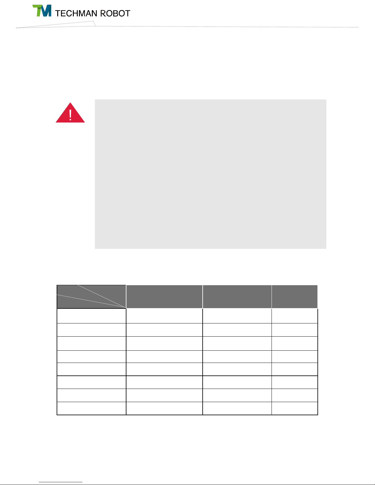
The Techman Robot System limits physical values such as offset, speed, force, or even
momentum and power, for the robot arm, tool end, and each movable axis. These are monitored
and protected by dozens of safety-related protection functions through the real-time system. The
figure below lists each protective function.
Location Speed/Momentum Force/Power
Robot
N.A Maximum robot momentum
Maximum robot power
Tool end
N.A Maximum speed of tool end
Force Applied to Tool
Endpoint
Axis 1
Minimum/Maximum axis position Maximum axis speed
Maximum axis torque
Axis 2
Minimum/Maximum axis position Maximum axis speed
Maximum axis torque
Axis 3
Minimum/Maximum axis position Maximum axis speed
Maximum axis torque
Axis 4
Minimum/Maximum axis position Maximum axis speed
Maximum axis torque
Axis 5
Minimum/Maximum axis position Maximum axis speed
Maximum axis torque
Axis 6
Minimum/Maximum axis position Maximum axis speed
Maximum axis torque
Limit type
Limit condition
Personnel limit
Danger
Page 14
9I Hardware Installation Manual 2. Safety Functions and Interface
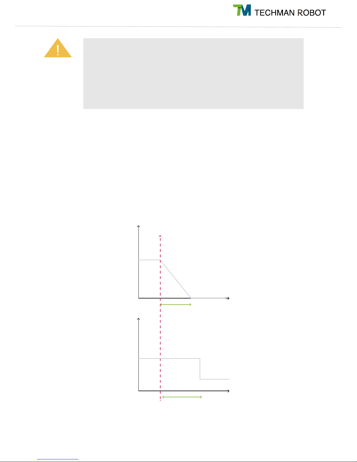
2.2 Safe Stop Time
The safe stop time is defined as the period from the moment when the Emergency Stop button is pressed
or any safety-related function is triggered to the moment when the robot comes to a complete stop. In this
system, pressing the Emergency Stop Button is a Category 1 Stop, while triggering built-in safety-related
functions or externally connected safety-related equipment is a Category 2 Stop. In certain cases, the user
or system integrator must include this time in the risk assessment, because the robot may operate at a
certain speed during this period, allowing transfer of energy, which may cause personal injury or equipment
damage, please refer to Appendix A for the actual stopping distance.
Both (A) and (B) are actuated during a Cat. 1 stop by the system; only (A)
actuates during a Cat. 2 stop.
The "Force Applied to Tool Endpoint" is the external force which is applied at the center point of
the tool, and estimated by models. It is not the protection value for the force externally applied
by the robot system to the center point of the tool. When the external force applied to the center
point of the tool estimated by the robot system exceeds this setting value, the event "Exceed
Limit of Force Applied to Tool Endpoint" is triggered. At this time, the robot performs Category
2 Stop and starts deceleration. The robot may still apply force externally until it comes to a
complete stop. Thus, it should be understood that the force externally applied by the robot
during the period from this time to a complete stop will exceed this setting value. This setting
must not be mistakenly used as a basis to assess the force of collision between human and
machine.
Warning
500ms
20A
3A
800ms
Joint speed
Motor driving
current
(A)
(B)
Trigger of safety alarm event
Page 15

I Hardware Installation Manual 2. Safety Functions and Interface10
2.3 Safety-related Limiting Mechanisms
All safety-related functions described in Section 2.1 are monitored and controlled by a dedicated safety
thread (with a cycle of 10ms) at system level, which provides a trigger signal to another dedicated motion
thread (with a cycle of 1ms) to make related responses. In this dedicated safety thread, all physical
quantities used for calculation of the required information about each robot axis (angle, angular velocity,
torque, etc.) are also updated every 1ms. When any safety related function is triggered, every axis of the
robot will stop within 800ms under a Category 2 Stop. When the Emergency Stop button is pressed, the
robot will stop movement within 610ms and the system will lower the upper limit of the total drive current
from 20 A to 3 A to activate a Category 1 Stop. In addition, when system hardware is operating beyond
limits (such as too high joint drive current, overheating motor, unstable power supply, or disconnection of
the system communications), a Category 2 Stop is triggered. When a Category 1 Stop or Category 2 Stop is
triggered, the Indication Light Ring on the end of the robot will change to a solid red light and the system will
beep continuously. When this happens, restart the system according to standard procedure, or contact the
distributor for servicing.
2.4 Singularity/Singular Point
Robot arm do not move through whole space always, it has a number of safety-related issues. Kinematic
singularities play a significant role in the motion control of robot arm. Singularity can be defined as a posi-
tion in the robot workspace where two or more joints no longer independently control the position and orien-
tation of the tool. Namely, for a general 6-axis manipulator, this means that singularity is a point where the
robot loses its ability to move the tool center point in some orientations. The error code are 0x09、0X14.
TM robots with 6 degrees of freedom have three clarifications in singularity:
● Inner singularity
● Extended singularity
● Wrist axis singularity
Operating on the periphery of the non-working area of the Techman robot or if the range of motion
passes through the non-working area (Jacobian matrix is unstable near singularities) may also
cause the end tool output force to incorrectly trigger safety conditions even at low speeds. Please
set the task requirements of the robot inside its working space to ensure the correct operation of
the safety protection.
Warning
Page 16

11I Hardware Installation Manual 2. Safety Functions and Interface
Inner singularity
In the inner singularity, the wrist root point is close to cylindrical as shown in below. The definition of cylin-
drical radius , is distance between center of J1 and J6. Once robot arm close the inner singularity, robot arm
will stop and sent out a warning.
The d
offset
is 122.2 mm.
Extended singularity
In the outer singularity, the wrist root point is located at the limit of its work envelope. Namely, J3 is almost in
zero degree. Robot arm stop and send out a warning when end-effector beyond working space.
Joint coordinate system and d
offset
definition.
Page 17

I Hardware Installation Manual 2. Safety Functions and Interface12
Wrist axis singularity
In the wrist singularity position, the J4 and J6 line up each other. In this case, these joints will try and spin
180 degrees instantaneously. There is an infinite number of possible for J4 and J6 with identical axis angle.
Once situation mentioned occur, robot arm will stop and send out a warning.
The workspace explanation when J3 is almost in zero degree.
There is an infinite number of solution space when axes J4 and J6 with
identical axis angle.
Page 18

13I Hardware Installation Manual 2. Safety Functions and Interface
When encountered singularity
When the robot reports the error code 0x09 or 0x14, it may be caused by singularity, please confirm robot
pose. If robot trajectory passes through inner Cylinders like picture as below, please refer to the first point
as below. If J4 and J6 with identical axis angle, please refer to the second point as below.
1.While robot arm send out a warning because of inner singularity, user can press the FREE bottom to
get rid of warning. Please reconsider the position of the points or change the trajectory between the points.
Please avoid the robot trajectory between the points cross the inner singularity.
2 .While robot arm send out a warning because of wrist axis singularity, user can press the FREE button to
get rid of warning. Try to move the robot along z-axis in tool base when J4 and J6 with identical axis angle
will cause wrist axis singularity. The picture below shows an example to prevent wrist axis singularity.
When robot trajectory passes through inner singularity, it will send out a
warning.
An example to prevent wrist axis singularity
Page 19

I Hardware Installation Manual 2. Safety Functions and Interface14
2.5 Safety setting
Safety setting of TM Robot is divided to Safety Stop Criteria, Safety IO Setting and Collaboration mode.
Safety Stop Criteria :
User can modify the maximum allowable values of robot momentum, power con-
sumption, TCP speed, TCP force, joint position, joint speed and joint torque in Safety Stop page.
Min/Max Joint Position Setting :
If you set the Min/Max position of first joint with 270˚ and -270˚, then the angle range in 270˚~ 271˚and
-270˚~ -271˚ will become reducing range as the blue area showed in the picture. When the first joint
move into this range the basic moving speed of the robot will be switched to 250mm/sec for path motion
and 5% for PTP motion, to forming an angle buffer region to prevent possible overshoot to the joint limit.
At the same time, the angle range in 271˚~ 274˚and -271˚~ -274˚ is the 2nd buffer range for joint limit as
the red area in the picture. When the joint angle arrives this area robot will stop moving. User can only
operate the robot by press free robot button until robot leaves this area.
Page 20

15I Hardware Installation Manual 2. Safety Functions and Interface
Safety IO Setting :
Safety IO Setting (Please refer to description in 5.3.1) compose two modes: Pause and
collaboration mode. User can choose either pause or collaboration mode in safety IO setting.
ause: Setting the configuration of the safety IO of TM Robot with risk evaluation, user can choose either
“
manual reset” or “automatic reset” to manually restart or automatically restart the project when the project
is previously paused by safety IO triggered.
Collaboration mode:
Setting the configuration of the safety IO of TM Robot with risk evaluation, user can
utilize the collaboration mode to switch the project from full speed mode to collaboration mode, when safety
IO triggered.
Collaboration Mode setting: Parameter configuration for TM Robot’s collaborative mode can be divided into
two parts. One is hazard configuration and the other is limit configuration. (Please refer to description in 2.8.1).
Page 21

I Hardware Installation Manual 2. Safety Functions and Interface16
2.5.1 Operating Position
Except for Hand Guide Mode, for correct operating positions, the user should stay outside of the mo-
tion range of the robot to perform operations. At least one emergency switch is installed outside of
the motion range of the robot. When no motion limit is set for the robot, the motion range of the robot
is equal to the maximum motion range of the robot arm (refer to Section 4.2.1). When the user sets
a limit for the TM Robot, he/she can avoid the situation whereby all operations have to be out of the
maximum motion range of the robot arm.
The robot stick should be placed in an area that the robot cannot reach. The user should also make
sure that the movement of the robot will not be within any area where personnel will enter to press
any buttons on the robot stick.
2.6 Operating Mode
TM Robot comes with two operating modes: Manual Mode and Auto Mode. Current mode can be deter-
mined visually via the mode indicator (see Section 4.2.3.1) on the Robot Stick, and the color of the Indica-
tion Light Ring on the robot's end module (see Section 4.2.2.4). The robot starts in Auto Mode.
2.6.1 Auto Mode
When the robot is in Auto Mode the Indication Light Ring on the end module is blue and the mode in-
dicator on the Robot Stick is in the Auto position. Under auto mode, pressing the Play/Pause buttons
on the Robot Stick runs or pauses the project. Robot speed is determined by the project speed. The
FREE button of the end module does not work under Auto Mode so there is no guiding by hand.
2.6.2 Manual Mode
When the robot is in Manual Mode the Indication Light Ring on the end module is green and the
mode indicator on the Robot Stick is in the Manual position. Manual Mode can be further broken
down into Manual Control mode and Manual Trial Run Mode. The user can tell the difference using
the status of the green Indication Light Ring on the end module as well. Constant green light indi-
cates Manual Control mode while flashing green light indicates Manual Trial Run Mode.
2.6.2.1 Manual Control Mode
In Manual Mode, if the robot is not moving then it is in Manual Control mode. Press the FREE
button on the end module to guide the robot by hand or use the controller page to jog the
robot. When the robot is in Manual Control Mode, all robot motion will be limited to less than
250mm/sec. If the robot speed exceeds 250mm/sec then it will stop on an error.
2.6.2.2 Manual Trial Run Mode
When the user is in the HMI's project editing page, pressing the Play/Pause button on the
Robot Stick enters Manual Trial Run Mode. The 250mm/sec speed limit does not apply while
editing projects in Manual Trial Run Mode but the project run speed will be reduced to 10%
during each trial run. The add/subtract buttons on the Robot Stick can be used to adjust the
project run speed in Manual Trial Run Mode. Each button press increases or decreases proj-
ect run speed by 5%. This is used to adjust the project run speed.
Page 22

17I Hardware Installation Manual 2. Safety Functions and Interface
2.6.3 Changing the Operating Mode
To change the operating mode of the robot, please use the Mode Switch Button on the robot control
to cycle between Auto/Manual mode. The system cannot be changed from Auto to Manual mode
while the robot is running a project in Auto mode. The robot must be stopped by pressing the Stop
Button on the Robot Stick before it can be switched to Manual mode. When the robot is switched
from Manual Trial Run Mode to Auto mode by pressing the Mode Switch Button, the project run
speed will be set to the default project running speed. In other words, the run speed in Auto mode for
this project will now be fixed unless it is changed by another trial run.
2.7 Hold to Run
TM Robot can not only record points through hand guide instruction but also use TM Flow to move the coor-
dinates of each coordinate system. These include: moving the joint angle, moving the end module through
the robot coordinate system, moving the end module through the tool coordinate system, moving the end
module through a custom coordinate system, moving to the vision initialization position, visual servo oper-
ations, execute step run function, and move to point. In all of the above functions, a hold to run design was
adopted by TM Robot for enhanced safety. There are two types of hold to run in the TM Robot system. For
operations with a higher level risk, the Robot Stick should be used to carry out different types of hold to
run functions. Type 1 is holding down the add/subtract buttons on the Robot Stick to keep the robot mov-
ing. Type 2 is holding down the software buttons on the HMI to keep the robot moving. Both move the robot
while
the button is held down and stops immediately when the physical or virtual button is released. The robot will
resume running if the button is held down again. Some of the functions can be used by both types of hold
to run functions so the user can choose one of the Types to operate. However, if you are using the software
hold to run button from a HMI connected to the robot via TCP/IP or Wi-Fi, if the network is disconnected
then the TM Robot system will automatically disengage the robot and make it stop. In this situation however,
it may take up to 0.7 second for a disconnection to be detected under different network environments. This
means that even if you release the software button the robot may continue to execute the original command.
If the physical button on the Robot Stick is used for hold to run, the system's detection time for button re-
lease is 30 ms. For operations with a higher level risk, the Robot Stick should therefore be used with all hold
to run operations.
Page 23

I Hardware Installation Manual 2. Safety Functions and Interface18
Danger
Danger
Please note that the functions described in this chapter are only intended to speed up the con-
figuration of collaborative safety parameters and settings by the user. It is still up to the user to
conduct a full risk assessment based on the robot's operating environment and conditions be-
fore use. TM Robot explicitly states that serious residual risk may exist in the following scenari-
os: Improper configuration of safety space or running incorrect project may lead to the risk of the
robot colliding with the human body at full speed.
When the TM Flow Compliance function is used within the safety zone, the robot will run the
Compliance function at the set force since it is not controlled by collaborative mode. Please
complete a thorough risk assessment and set an appropriate level of force before using the
Compliance function in collaborative mode.
2.8 Collaborative Mode and Safety Zone Setup
TM Robot can run in standard mode or collaborative mode. In collaborative mode, the robot will run at a
slower speed and use a lower torque based on the user settings. The robot status light will add purple light
display to let the user know whether the robot is in collaborative mode. Please refer to the table in Section
4.2.2.4 for complete light information.
2.8.1 Collaborative Mode and Parameter Configuration
Parameter configuration for TM Robot’s collaborative mode can be divided into two parts. One is
hazard configuration and the other is limit configuration. The hazard configuration page is as shown
below.
Page 24

19I Hardware Installation Manual 2. Safety Functions and Interface
Danger
In this function, the robot speed is calculated according to the durable force and pressure on
medical reports which conform to ISO/TS15066. In addition to the body parts showed in the fig-
ure, other vulnerable body parts such as spine, hindbrain and etc., should be taking into consid-
eration for risk assessment to avoid any possible of collision with TM robot.
For hazard configuration, user can define the locations with risk of robot contact with the human body
within the collaborative space. The robot’s operating speed in collaborative mode and other data
will be shown on the right side of the interface. The settings can be saved once they are confirmed
by the user. The data include the automatic pathing speed and automatic point-to-point movement
speed, when entering the collaborative zone and the surface area of tools that may come into con-
tact with the human body. User should tick the confirmation box in the lower right corner before sav-
ing the settings to confirm the surface area of any potential contact between tools mounted on the
robot and the human body will be larger than or equal to the surface area being confirmed.
Please note that while the values for some calculated data can be modified by the user, only smaller
values can be used. If more detailed parameters must be configured by the user, they can be modi-
fied from the “Additional Limit Configuration Page” as shown below.
In this configuration page for collaborative mode, the user can set servo speed, and servo torque.
Please note that these settings must be smaller than the settings of standard mode. Settings can be
saved once they have been confirmed by the user.
Page 25

I Hardware Installation Manual 2. Safety Functions and Interface20
Danger
Except for defining the safety space setting as all safety space setting as all safety space, the
TM Robot safety space cannot be utilized as a safety device solely. User must conduct a full risk
assessment based on the robot’s operating environment and conditions before use. User can
utilize the qualified safety light curtain, safety laser scanner or other safety devices accompanied
with the instructions in section 2.5 & 5.3.1 about the pause or collaboration actions triggered by
external device via safety IO for correct setup. Other proper design or setup of safety working
environment can also be conducted to prevent people from entering the full speed area. Please
note that the functions described in this chapter are only intended to provide user a clear view of
the safety space setting in 3D space during teaching mode and programming. Also, the safety
planes and spaces setup for collaboration are only intended to assist user recognizing the set-
up of collaboration area and full speed area. The safety planes and spaces cannot be utilized
as a safety function to switch between collaboration mode and full speed mode solely. When
applying the stop planes and spaces in teaching mode, points and motion in forbidden area are
not allowed. The stop planes and spaces cannot be utilized as a safety function to constrain the
robots work space solely. TM Robot explicitly states that serious residual risk may exist in the
following scenarios: Improper configuration of safety space or running incorrect project may lead
to the risk of the robot colliding with the human body at full speed.
2.8.2 Collaborative Space Configuration for Safety
TM Robot offers two ways of configuring the safety space attributes: Planar and Cubic. If the robot
enters the safety space during operation, it will switch to collaborative mode. Planar attributes allow
the user to set either safety plane or stop plane. Cubic can only be used to define safety spaces.
The left side of this page is used for collaborative space configuration. The 3D simulator is in the mid-
dle and the controller interface is on the right side.
Safety Space Configuration Tab:
Click on the safety space to enter this safety space setting page in robot setting page.
Page 26

21I Hardware Installation Manual 2. Safety Functions and Interface
Previously defined attributes will be shown in the list. When the user selects a listed attribute, the 3D
simulator in the middle will display the selected attribute in a transparent blue color. The user can
then delete or reset the selected attribute. The window for setting start reduce distance will appear
after the Start Reduce Distance setting button pressed, and the user can set the distance for the
collaboration area and stop space separately. The robot will start to reduce the motion speed when
moving in the start reduce zone, but the status of the indication light ring would not be change.
Add/Edit Plane Tab:
The collaborative space configuration functions are as shown below.
Add Plane
Add Cube
Delete Selected Attribute
Reset Attributes
Set Start Reduce Distance
Switch to Safety Plane
Switch to Stop Plane
Reverse Stop Space
Safety Plane
Stop Plane
Delete
Set Point
Plane chareacters
Page 27

I Hardware Installation Manual 2. Safety Functions and Interface22
Press the Add Plane button or select a planar attribute then click on the Reset Attribute button to en-
ter the Add/Edit Plane page. In this page, the user can use TCP to define 3 points and create a plane.
The 3 points can be defined in any order and corresponding colored spheres will appear in the 3D
simulator. Once all 3 points have been set, then a transparent blue virtual plane will appear. Now,
click on the Confirm button to create the plane. Please note that the virtual plane will not appear if
there are common points or the points are collinear. In this case clicking on Confirm will not create a
plane.
The button functions are as shown below.
Add/Edit Cube Tab
Set the first point
Set the second point
Confirm plane creation
Cancel plane creation
OK Cancel
Set the third point
Page 28

23I Hardware Installation Manual 2. Safety Functions and Interface
Danger
The safety space setting is achieved by complex algorithms. Under specific settings, the setting
result may not be as expected. User is responsible for assuring the result shown in 3D figure is
correct. Improper configuration of safety space or running incorrect project may lead to the risk
of the robot colliding with the human body at full speed.
Set the first point Set the second point
Confirm cube creation
Cancel cube creation
OK Cancel
Set the third point Set the fourth point
When finishing the safety space setting, user can access the safety space setting through the col-
lapsible on the right side of the project page.
Press the Add Cube button or select a cubic attribute then click on the Reset Attribute button to enter
the Add/Edit Cube page. In this page, the user can use TCP to define 4 points and create a cube.
The 4 points can be defined in any order and corresponding colored spheres will appear in the 3D
simulator, but it should follow the indicated rules. Once all 4 points have been set then a transparent
blue virtual cube will appear. Now click on the Confirm button to create the cube. Please note that
the virtual cube will not appear if there are common points or the points are collinear. In this case
clicking on Confirm will not create a cube.
The button functions are as shown below.
Page 29

I Hardware Installation Manual 2. Safety Functions and Interface24
Danger
The Intelligent Slowdown function will be activated if the position of the TCP start point is in the
full speed area and the TCP end point is in the collaboration area. As a result, the Intelligent
Slowdown function will not be activated if the start point and the end point are both located in
the full speed area, even though the motion path passes through the collaboration area.
Intelligent Slowdown function can force the robot to slow down before exiting the full speed area to
collaboration area. The motion of TM ROBOT when applying Intelligent Slowdown is in accordance
with the position of the start point and the end point and the type of motion setting.
Please access the safety setting via the collapsible on the right side of the project page. When pre-
view button is pressed, the 3D simulator will show the bound safety space with the chosen safety
setting and binding base. Edit function allows the user to modify the safety space shown in 3D sim-
ulator. User should be responsible for his own safety and assure the result shown in 3D figure is
correct. For safety space not shown as expected, please delete the latest safety plane and reset the
safety space via edit function.
The generated safety space is displayed on the 3D simulator.
Remove/add/edit planes to modify the safety space shown in
3D simulator.simulator.
Save the safety space shown in 3D simulator.
Preview
Edit
Save
Page 30

25I Hardware Installation Manual 2. Safety Functions and Interface
Click on the preview button. If the safety space needs to be modified, then click on the Edit button
below Step 2 and modify it in the setting page.
If the modification is complete, click on the Save button at the top to save and leave this page.
If you do not need to modify, you can click on the X button at the top right corner and return to the
settings page without save.
Page 31

I Hardware Installation Manual 3. Transportation 26
3. Transportation
Transport the Techman Robot using its original packing materials. If you will need to transport the Techman
Robot after unpacking, store the packing materials in a dry place. Hold both arms of the Techman Robot
during transportation. Support the arms before tightening the base screws.
Transport the control box by its handles. Store the cables before transportation.
Pay attention to your posture when moving the arm and control box cartons to avoid back injury. Tech-
man Robot will not be liable for any injuries cased during transportation.
Warning
Page 32

27I Hardware Installation Manual 4. System Hardware
Robot arm
Control Box
Robot Stick
4. System Hardware
4.1 Overview
This chapter introduces the mechanical interface of the Techman Robot System.
4.2 System Overview
Techman Robot is made up of the robot arm and control box (including a robot stick).
Page 33

I Hardware Installation Manual 4. System Hardware28
4.2.1 Robot Arm
4.2.1.1 Robot Range of Motion
Techman Robot's working range is a spherical space with a 700mm radius at the base (for
TM5-900, it is a 900mm radius). Due to the limitations of configuration, try to avoid moving the
center of the tool to the cylindrical space below and above the base.
TM5-700 Movement Range Diagram
Page 34

29I Hardware Installation Manual 4. System Hardware
Operator Position
Warning: Risk of crushing
within the operating area of
the arm.
Warning: Risk of collision within
the operating area of the arm.
Page 35

I Hardware Installation Manual 4. System Hardware30
TM5-900 Movement Range Diagram
Operator Position
Warning: Risk of crushing
within the operating area of the
arm.
Warning: Risk of collision within
the operating area of the arm.
Page 36

31I Hardware Installation Manual 4. System Hardware
Page 37

I Hardware Installation Manual 4. System Hardware32
TM5-900/TM5X-900
4.2.1.2 Robot Arm Maximum Allowed Payload
The maximum allowed payload of the robot arm is related to its center of gravity offset, which
is defined as the distance from the center point of tool flange to the payload’s center of gravity.
The following figure shows the relationship between payload and the center of gravity offset:
TM5-700/TM5X-700
Page 38

33I Hardware Installation Manual 4. System Hardware
4.2.1.3 Robot Arm Installation
The TM5 is secured by four holes with a diameter of 11mm on the base and four M10 screws.
A tightening torque of 35Nm (can be adjusted based on the strength of the bolts used) is
recommended. If your application requires more precision, you can use two positioning pins
with a diameter of 6mm for a more secure mounting.
1. The Techman Robot must be securely and tightly screwed down before use. The mounting
surface should have sufficient strength.
2. Do not immerse the Techman Robot in water. Installation in the water or a humid environment
may lead to damage.
Danger
Page 39

I Hardware Installation Manual 4. System Hardware34
Analog I/O
VISION button
POINT button
FREE button
Digital I/O
Indication Light Ring
4.2.2 Robot End Module
4.2.2.1 End Module Components
GRIPPER button
Camera module
Flange (ISO 9409-1-50-4-M6)
Page 40

35I Hardware Installation Manual 4. System Hardware
GRIPPER button
POINT button
Digital I/OAnalog I/O
FREE button
TM5X End Module Components
Flange (ISO 9409-1-50-4-M6)
Indication Light Ring
Page 41

I Hardware Installation Manual 4. System Hardware36
4.2.2.2 End Flange Surface
Page 42

37I Hardware Installation Manual 4. System Hardware
4.2.2.3 End Mounting Caution
The TM5 uses four M6 threaded holes on the end flange and four M6 screws for mounting
tools. A tightening torque of 9Nm is recommended. If your application requires higher precision,
you can use two positioning pins with a diameter of 6mm for a more secure mounting.
4.2.2.4 End Indication Light Ring Table
The Indication Light Ring of the TM Robot has several colors which represent different modes
and error statuses. Look up the following table which contains troubleshooting methods:
Tools must be appropriately and securely tightened when using this product. Improper tightening
may cause the tool or part to fall out, or even cause personal injury and death.
Danger
Color/blinking Description Troubleshooting
Solid green light
Standby status in Manual Mode
(Manual Control mode)
N/A
Flashing green light
Project running in Manual Mode
(Trial Run mode)
N/A
Short Flashing Green light Project paused in Manual Mode. N/A
Alternating between Green/Red light
(with buzzer 2 beeping)
Manual Mode Error
Press the FREE button to troubleshoot
the error.
Solid blue light Standby status in Auto Mode N/A
Flashing blue light Project running in Auto Mode N/A
Short Flashing Blue light Project paused in Auto Mode N/A
Alternating between Blue/Red light
(with buzzer 2 beeping)
Auto Mode Error
After switching to Manual Mode, press
the FREE button to troubleshoot.
Light blue light Safe Startup Mode
Release the Emergency button to return
to the original mode.
Flashing red light Robot is initializing. N/A
Flashing red light (with buzzer 1
beeping)
Emergency stop pressed
Release the Emergency button to return
to the original mode.
Solid red light Buzzer emits a long
beep
Fatal error Shutdown and Restart required
Page 43

I Hardware Installation Manual 4. System Hardware38
When the user sets the safety space and the robot moves into the safety space, the robot will
enter the collaborative mode. At this time, the purple light will be added. Please refer to the fol-
lowing table for the definition of each status:
Mode Standby/running Space Color/blinking
Manual Mode
Standby status
Full speed Space Solid green light
Collaboration Space Alternating between Green(9)/Purple(1)
Stop Space Alternating between Green/Red
Project running
Full speed Space Flash green light
Collaboration Space Alternating between Purple/Red
Stop Space Alternating between Green/Red
Auto Mode
Standby status
Full speed Space Solid blue light
Collaboration Space Alternating between Blue(9)/Purple(1)
Stop Space Alternating between Blue/Red
Project running
Full speed Space Flash blue light
Collaboration Space Alternating between Purple/Red
Stop Space Alternating between Blue/Red
Page 44

39I Hardware Installation Manual 4. System Hardware
4.2.3 Control Box
The control box can be placed on the floor or on a rack. Note that 5cm clearance should be left at
both sides for air flow.
Note
4.2.3.1 Robot Stick
The Robot Sticks has 6 function buttons, 3 indicator lights, 1 emergency button, and 1 QR-
code. There functions are as follow:
Page 45

I Hardware Installation Manual 4. System Hardware40
Item Basic Function
Emergency Button Default emergency button for the robot
Power Button Bootup (single press)/ Shutdown (long press)
Mode Switch Button Cycle Manual/Auto Mode (single press). See Section 2.6 for details.
Play/Pause button Play/Pause Project (press once)
Stop button Stop Project (press once)
Add/Subtract button Adjust project speed (press once) under Manual Trial Run Mode. See Section 2.6
for details.
Power Indicator
Shows the robot's power status.
Not on: Switched off
Flashing: Booting
Constant:Startup completed
Mode Indicator Lights The two lights are Manual and Auto. They show the robot's current operating mode.
Once bootup is complete only one will always be on.
QR Code Label Shows the SSID of the robot's own software AP. The content of the SSID is also the
robot's name in TCP/IP network.
Item Advanced Function
Emergency Button Hold down before bootup to enter Safe Startup Mode.
Play/Pause button Play/pause visual calibration operation (press once)
Stop button Stop visual calibration operation (press once)
Add/Subtract button
- Hold to jog the robot at the HMI robot controller page (Hold to Run).See Section 2.7
details.
- Lock/ Unlock: hold down both add and subtract until the mode indicator flashes,
then follow the sequence "Subtract Add Subtract Subtract Add" when pressing the
add/subtract buttons to lock/unlock the Robot Stick (except the Power button)
Some of the function buttons offer the following advanced functions:
Page 46

41I Hardware Installation Manual 4. System Hardware
The robot stick is magnetic so that it can be attached to magnetic surfaces. However, the risk of
falling or rotating caused by poor attachment should be taken into account. It is recommended us-
ing the official Robot Stick Stand (official accessasory) to secure the robot stick. In that case, the
Robot Stick Stand should be fixed with screws. Do not freely place the robot stick when it is not
fixed. The robot stick should be placed in a way that the signal cables are routed properly to avoid
damage caused by pulling.
1. The control box, cables, power signal cables, and robot stick cannot be used when any of them
is in contact with liquids. This may result in personal injury or death.
2. The control box has an IP20 rating so that it cannot be used in environments with powder and
moisture. Particular attention should be paid to environments with conductive dust (such as metal
swarf).
Note
Danger
Page 47

I Hardware Installation Manual 5. Electrical Interface42
5. Electrical Interface
5.1 Overview
This chapter introduces all electrical interfaces of the robot arm and control box.
5.2 Electrical Warnings and Cautions
The application design and installation of the robot should comply with the warnings and cautions below.
1. Ensure all pieces of the equipment are kept dry. If water enters the equipment, disconnect the
power and contact your supplier.
2. Only use the original cables included with the robot. If you need longer cables, contact your
supplier.
3. Ensure the robot is properly grounded. If the grounding is not correct, it may cause a fire or
electric shock.
Danger
The I/O cables used for the link between the control box and other equipment should not be lon-
ger than 30 meters, unless testing shows that longer cables are feasible.
Warning
Page 48

43I Hardware Installation Manual 5. Electrical Interface
5.3 Control Box
5.3.1 Safety Connector
Provides expansion ports for Emergency Stop(ESTOP) & Safety Stop.
A) ESTOP is a N.C. contact (Normally closed). When ESTOP SW is OPEN,the robot arm enters the
Emergency STOP state.
B) Safety A&B is a N.C. contact (Normally closed). When Safety SW is OPEN,the robot arm enters
the Pause state.
Front control box configuration
Except for USB ports, other interfaces have to be installed while arm is shutdown. Do not install
while arm is on to avoid abnormal shutdown.
Warning
Page 49

I Hardware Installation Manual 5. Electrical Interface44
The factory safety settings are shown below. Operations can be performed without addition of safety
devices, as shown below.
Application settings of the arm safety device
Page 50

45I Hardware Installation Manual 5. Electrical Interface
5.3.2 Power Connector
A) During boot, the control box will check for an external 24V input. If none is available then it will
switch to the internal 24V supply.
B) The control box itself offers a 24V1.5A output (24_EX). If the 24V load exceeds 1.5A, it enters
Safe Mode and disables the 24V output.
C) EX24V provides an external 24V input port. If the load exceeds 1.5A an external power supply
can be used instead. The load on EX24V must not exceed 3.5A.
5.3.3 Digital In/Out
Digital In/Out have 16 Channel each, it should be connected as follows,
A) Digital Input: If sensors are connected directly then they should be of the NPN type.
Page 51

I Hardware Installation Manual 5. Electrical Interface46
B) Digital Output: The maximum drive current is 100mA per channel. If the load exceeds 100mA, a
relay should be used to drive it.
Page 52

47I Hardware Installation Manual 5. Electrical Interface
5.3.4 Analog In
Analog In only supports voltage mode and detection range of -10.00 V ~ +10.00 V.
Page 53

I Hardware Installation Manual 5. Electrical Interface48
5.3.5 Analog Out
Analog Out only supports voltage mode and detection range of -10.00 V ~ +10.00 V.
5.3.6 EtherCAT: For EtherCAT Slave I/O Expansion
5.3.7 USB Port
The USB port of the control box is used for connecting the keyboard, mouse and external storage
devices. External storage devices should only be used for the import/export functions of TM Flow. No
USB devices other than those listed above should be connected.
Robot must be powered off when installing the EtherCAT Slave. Do not plug or unplug the con-
nector while robot is on.
Warning
The large differences in the specifications of external storage devices on the market may inter-
fere with high-speed vision transmission while the robot is in operation so do not use your own
external storage devices while the robot is running. TM Robot's vision image storage function is a
value-added function that can only be used with the dedicated SSD kit sold through the TM Robot
website. Interested buyers should contact the TM Robot website.
Note
Page 54

49I Hardware Installation Manual 5. Electrical Interface
Pin Wire color Pin define
ᅠ
1 Brown +24V 24V output
2 Red DI_0 Digital intput0
3 Orange DI_1 Digital intput1
4 Yellow DI_2 Digital intput2
5 Green DO_0 Digital outtput0
6 Blue DO_1 Digital outtput1
7 Purple DO_2 Digital outtput2
8 Black +0V +0V
Pin Wire color Pin define
ᅠ
1 Brown +24V 24V output
2 Red DI_0 Digital intput0
3 Orange DI_1 Digital intput1
4 Yellow DI_2 Digital intput2
5 Green DO_0 Digital outtput0
6 Blue DO_1 Digital outtput1
7 Purple DO_2 Digital outtput2
8 Black +0V +0V
8-pin digital I/O connector of Robot
8-pin digital I/O connector of Cable
5.4 Tool End I/O Interface
There are two small connectors on the tool end of the robot: a 8-pin connector and a 5-pin connector.
5.4.1 I/O Terminals
The tool end 24V has a maximum output current 1.5A. If overloading, overload protection is activated
and the robot will turn off the 24V output power.
Page 55

I Hardware Installation Manual 5. Electrical Interface50
Pin Wire color Pin define
ᅠ
1 Black AI Analog Input
2 Brown RSV Reserve
3 Red RSV Reserve
4 Orange GND GND
5 Yellow GND GND
Pin Wire color Pin define
ᅠ
1 Black AI Analog Input
2 Brown RSV Reserve
3 Red RSV Reserve
4 Orange GND GND
5 Yellow GND GND
5-pin analog I/O connector of Cable
5-pin analog I/O connector of Robot
Page 56

51I Hardware Installation Manual 5. Electrical Interface
5.4.2 Connecting Tool End Digital Out
The following figure shows how to connect the tool end digital output:
5.4.3 Connecting Tool End Digital In
The following figure shows how to connect the tool end digital input:
A) If sensors are connected directly then they should be of the NPN
type.
Page 57

I Hardware Installation Manual 5. Electrical Interface52
5.4.4 Connecting Tool End Analog In
The following figure shows how to connect the tool end Analog input:
5.5 Control Box Interfaces
USB2.0
USB2.0
USB2.0
USB2.0
ETHERCAT
Robot Status Display
Robot Controller Stick Cable
Adjustable Wi-Fi Antenna
Page 58

53I Hardware Installation Manual 5. Electrical Interface
5.6 Control Box Power Interface and Robot Interface
5.6.1 Control Box Power Interface
The power cable of the control box has an IEC plug. The local power plug is connected to the IEC
plug.
The ETHERCAT interface can only be used to connect ETHERCAT devices. Improper connection may
cause stopping of the robot.
Note
The power supply should be equipped with the following
devices:
• Grounding
• Main fuse
• Residual current device (RCD)
It is recommended to install a main switch on the equipment
power supply for robot applications for servicing and
inspection purpose.
Page 59

I Hardware Installation Manual 5. Electrical Interface54
Parameters Minimum value Typical valueᅠMaximum value Unit
Input voltage 100 - 240 VAC
External mains fuse
(100V~120V)
- - 15 A
External mains fuse
(200V~240V) - - 8 A
Input frequency 43 - 63 Hz
The table below shows the electrical specifications:
1. Ensure that the robot is correctly grounded (electrical grounding).
2. Ensure that the input current of the control box is protected by the Residual Current Device
(RCD) and appropriate fuses.
3. Ensure that all cables are correctly connected before the control box is energized. Always use
genuine power cables correctly.
Danger
5.6.2 Robot Interface
The following figure shows the connection interface of the robot. The cables of the robot are
connected to the control box through the interface.
1. When the robot is turned on, do not disconnect cables of the robot. When cables of the robot
are not connected to the connection interface, do not turn on the robot.
2. Do not extend or modify the original cables of the robot.
Warning
Page 60

55I Hardware Installation Manual 6 ~ 7
6. Maintenance and Repair
Maintenance of Techman Robot: Clean the exterior of the Techman Robot periodically, and keep the moving
joints clean. The filter of the control box must be cleaned or replaced periodically (determine how often the
filter is cleaned or replaced depending on the cleanliness of surroundings).
Only the legal distributor or authorized service center should repair the Techman Robot. The user should
not repair it himself or herself.
7. Warranty Statement
7.1 Product Warranty
The user (customer) may make a request to his/her dealer and retailer within any reasonable situation. The
manufacturer will provide warranty under the following conditions:
During the first twelve months of the warranty period (no more than 15 months from the date of shipment),
Techman Robot will provide necessary spares for malfunctioned parts of new equipment due to production
and manufacture error or damage. If the user (customer) has to bear labor costs, a new or refurbished part
can be used for servicing. If equipment defects are caused by improper handling or failure to comply with
manual requirements, this guarantee is invalid. Warranty services do not cover operations conducted by
the dealer or user, such as arm installation, software download. Your warranty request must be made two
months before the warranty is expired. All replaced or returned items are the property of Techman Robot.
This warranty does not cover other requests directly or indirectly related to equipment. No conditions of this
warranty shall attempt to limit or exclude customer's statutory rights or manufacturer's responsibility for
personal injury or death due to negligence. The warranty cannot be extended, even if it is the initial warranty.
Techman Robot reserves the right to charge customers for replacement or service costs, as long as no
warranty terms are violated.
The above-mentioned rules shall not imply a change in the burden of proof to the detriment of the interests
of customers. When equipment becomes defective, we are not liable for compensation for any indirect,
incidental, special, or corresponding damage, including but not limited to profit loss, loss of use, production
loss or other production equipment damage.
When the robot finishes a job and enters maintenance or servicing status, the user should record the
details of each setting for the job; after repairing and installing it to the work position, the user must
make sure that each setting satisfies the original conditions before resuming working status, including
but not limited to:
- Safety Software Settings
- Safety I/O
- Preset operation project
- TCP Settings
- I/O Settings
- I/O Wiring
Danger
Page 61

I Hardware Installation Manual 6 ~ 756
7.2 Disclaimer
Techman Robot will continuously improve the reliability and performance of the product. Therefore, we
reserve the right to upgrade the product without prior notice. Techman Robot has verified the accuracy and
correctness of this Manual, but will not liable for any erroneous or omitted information.
Page 62

57Appendix
Stop Time and Distance Table
Axis 1 Axis 2 Axis 3
Load (kg) Axis speed
(˚/sec)
Stop time
(ms)
Stop distance
(˚)
Stop time
(ms)
Stop distance
(˚)
Stop time
(ms)
Stop distance
(˚)
2
36 600.44
6.912 600 7.25 598.78 7.238
72 601.3 13.764 600.52 14.042 601.08 14.22
108 598.794 20.61 600.2 21.034 599.98 21.244
144
593.07 27.438 597.56 27.876 600.68 27.95
180 594.94 33.28 600.84 34.006 598.36 34.95
4
36
602.25
6.86 598.82 7.148 600.16 7.114
72 600.31 13.71 600.04 14.222 600.5 14.27
108
600.55 20.51 600.02 21.012 600.74 21.076
144 601.08
27.346
601.3 27.862 598.96 28.082
180 594.44 33.834 598.82 34.972 601.72 34.976
6
36 600.14 6.83 598.976 7.194 599.56 7.162
72 599.64 13.616 598.3 14.19 601.68 14.186
108 599.98 20.526 598.7 21.034 599.24 20.962
144 600.48 26.766 600.04 27.76 599.68 27.98
180 598.09 33.986 600.68 34.892 600.76 35.044
Appendix A. Stop Time and Distance
Page 63

Appendix58
Model TM5-700 TM5-900 TM5X-700 TM5X-900
Weight
22kg 22.2kg 21.7kg 21.9kg
Payload
6kg 4kg 6kg 4kg
Reach
700mm 900mm 700mm 900mm
Joint ranges:
J
1
:
+/- 270˚
J
2,J4,J5
:
+/- 180˚
J
3
:
+/- 155˚
J
6
:
+/- 270˚
Speed:
J
1~J3
:
180˚/s.
J
4~J6
:
225˚/s.
Repeatability
+/- 0.05 mm
Degrees of freedom
6 rotating joints
I
/
O ports:
Digital in
Digital out
Analog in
Analog out
Control box
16
16
2
1
Tool conn.
3
3
1
0
I
/
O power supply
24V 1.5A for control box and 24V 1.5A for tool
IP classification
IP54(Arm)
Power consumption
Max. 1300 watts
Temperature
The robot can work in a temperature range of 0-50˚c
Power supply
100-240 VAC, 50-60 Hz
I
/
O Interface of Control Box
3×COM, 1×HDMI, 1×EtherCAT, 2×GigE, 1×LAN,
4×USB2.0, 2×USB3.0, 1×VGA
Robot Vision
Eye in Hand
(
Built in
)
1.2M/5M pixels, color camera N/A
Eye to Hand
(
Optional
)
Support Maximum 2 GigE cameras
Technical Specifications
Appendix B. Technical Specifications
Page 64

59Appendix
 Loading...