

Page 1
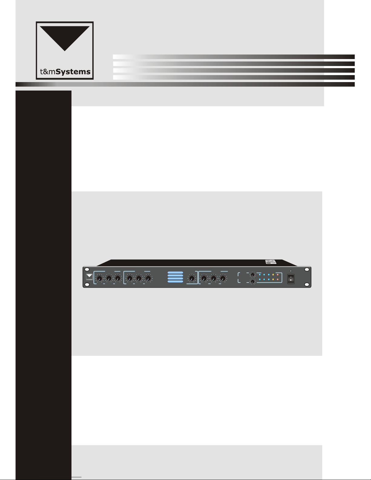
PROJECTMIX241
Please follow the instructions in this manual to obtain the optimum results from this unit.
We also recommend that you keep this manual handy for future reference.
OPERATION MANUAL
+3
0 -3 -8
-13
OUTPUT LEVEL
POWER
MIC 1
LEVEL TREBLE BASS
MIC 2
LEVEL TREBLE BASS
MUSIC
LEVEL
TREBLE BASS
SOURCE
PROJECT
MIX241
LEFT
RIGHT
MASTER
Page 2

TABLE OF CONTENTS
1. SAFETY PRECAUTIONS .........................................................................................3
2. ................................................................................................................ 4
3. GENERAL DESCRIPTION ......................................................................................5
4. FEATURES .................................................................................................................5
5. NOMENCLATURE AND FUNCTIONS
5.1 Front Panel ............................................................................................................... 6
5.2 Rear Panel................................................................................................................7
6. ..................................................................................8
6.1
7.
8.
9. ...................................................................................... 13
10.
11.
ATTENTION
OPERATION ILLUSTRATION
Power Indicatior.............................................. ...................................................8
6.2 Power Switch.............................................. ....................................................... 8
6.3 Power input.............................................. .......................................................... 8
6.4 Left/Right input interface (XLR)........................................... .. .........................9
6.5 REC Recorder input interface .............................................. ........................... 9
6.6 Line(1~4) inputs.............................................. ................ ................................10
6.7 Alarm Inputs.............................................. .......................................................1 0
6.8 MIC 1/MIC 2 balanced microphone input and Stubbs address code switch
............................................................................................................................11
EQUIPMENT INNER DRAWING.............................................. .............................. 12
INSTALLATION STEPS.............................................. ........................................12
CONNECTION DRAWING
BLOCK DRAWING............................................................................................. 14
SPECIFICATION................................................................................................ 15
12.INSTALLATION.......................................................................................................16
2
Page 3
Be sure to read the instructions in this section carefully before use.
Make sure to observe the instructions in this manual as the conventions of safety symbols and messages
regarded as very important precautions are included.
We also recommend you keep this instruction manual handy for future reference.
Safety Symbol and Message Conventions
Safety symbols and messages described below are used in this manual to prevent bodily injury and property
damage which could result from mishandling. Before operating your product, read this manual first and
understand the safety symbols and messages so you are thoroughly aware of the potential safety
Indicates a potentially hazardous situation which, if mishandled, could
result in death or serious personal injury.
Indicates a potentially hazardous situation which, if mishandled, could
result in moderate or minor personal injury, and/or property damage.
When Installing the Unit
Do not expose the unit to rain or an environment
where it may be splashed by water or other liquids,
as doing so may result in fire or electric shock.
Use the unit only with the voltage specified on the
unit. Using a voltage higher than that which is
specified may result in fire or electric shock.
Do not cut, kink, otherwise damage nor modify the
power supply cord. In addition, avoid using the
power cord in close proximity to heaters, and never
place heavy objects -- including the unit itself -- on
the power cord, as doing so may result in fire or
electric shock.
Be sure to replace the unit's terminal cover after
connection completion. Because high voltage is
applied to the speaker terminals, never touch these
terminals to avoid electric shock.
Be sure to ground to the safety ground (earth)
terminal to avoid electric shock. Never ground to a
gas pipe as a catastrophic disaster may result.
Avoid installing or mounting the unit in unstable
locations, such as on a rickety table or a slanted
surface. Doing so may result in the unit falling
down, causing personal injury and/or property
damage.
When the Unit is in Use
Should the following irregularity be found during
use, immediately switch off the power, disconnect
the power supply plug from the AC outlet and
contact your nearest dealer. Make no further
attempt to operate the unit in this condition as this
may cause fire or electric shock.
If you detect smoke or a strange smell coming
from the unit.
If water or any metallic object gets into the unit
If the unit falls, or the unit case breaks
If the power supply cord is damaged (exposure of
the core, disconnection, etc.)
If it is malfunctioning (no tone sounds.)
To prevent a fire or electric shock, never open nor
remove the unit case as there are high voltage
components inside the unit. Refer all servicing to
your nearest dealer.
Do not place cups, bowls, or other containers of
liquid or metallic objects on top of the unit. If they
accidentally spill into the unit, this may cause a fire
or electric shock.
Do not insert nor drop metallic objects or
flammable materials in the ventilation slots of the
unit's cover, as this may result in fire or electric
shock.
1. SAFETY PRECAUTIONS
3
Page 4

An all-pole mains switch with a contact separation of at least 3 mm in each pole shall be incorporated in
the electrical installation of the building.
When Installing the Unit
Never plug in nor remove the power supply plug
with wet hands, as doing so may cause electric
shock.
When unplugging the power supply cord, be sure
to grasp the power supply plug; never pull on the
cord itself. Operating the unit with a damaged
power supply cord may cause a fire or electric
shock.
When moving the unit, be sure to remove its power
supply cord from the wall outlet. Moving the unit
with the power cord connected to the outlet may
cause damage to the power cord, resulting in fire or
electric shock. When removing the power cord, be
sure to hold its plug to pull.
Do not block the ventilation slots in the unit's cover.
Doing so may cause heat to build up inside the unit
and result in fire.
Avoid installing the unit in humid or dusty locations,
in locations exposed to the direct sunlight, near the
heaters, or in locations generating sooty smoke or
steam as doing otherwise may result in fire or
electric shock.
When the Unit is in Use
Do not place heavy objects on the unit as this may
cause it to fall or break which may result in
personal injury and/or property damage. In
addition, the object itself may fall off and cause
injury and/or damage.
Make sure that the volume control is set to
minimum position before power is switched on.
Loud noise produced at high volume when power is
switched on can impair hearing.
Do not operate the unit for an extended period of
time with the sound distorting. This is an indication
of a malfunction, which in turn can cause heat to
generate and result in a fire.
Contact your dealer as to the cleaning. If dust is
allowed to accumulate in the unit over a long
period of time, a fire or damage to the unit may
result.
If dust accumulates on the power supply plug or in
the wall AC outlet, a fire may result. Clean it
periodically. In addition, insert the plug in the wall
outlet securely.
Switch off the power, and unplug the power supply
plug from the AC outlet for safety purposes when
cleaning or leaving the unit unused for 10 days or
more. Doing otherwise may cause a fire or electric
shock.
ATTENTION2.
4
Page 5

This series two-channel pre-amplifier with the latest styles to meet the needs of small and medium
sized public address system.Two-channel pre-amplifier has 2 inputs at the same time,cac enhance the
audio signal simutenously . Two-channel audio pre-amplifier is the connector of all audiou sources
(including common sources such as CD drive, modem, sound recording deck , MP3 players , special
audio alarm and a variety of microphones ) and the power amplifier devices.The volume of each input
source can be adjusted independently,with priority ranking function,which can require the input source
to prioritize. Two-channel pre-amplifier has sound quality control functions,such as through its ring
tone control circuit or other control circuit, to regulate and control the frequency characteristics of
signals,to play modified and beautifythe sound, and meet the requirementsof the listener's preferences.
Standard chassis design, 1U aluminium alloy; light equipment, simple operation, artistic and
practical
Each input independent volume and treble /bass volume adjustment
MIC 1-2 balanced microphone inputs with +48 phantom power switch and gain adjustment
With alarm generator, to provide for the paging tone
LINE 1-4 line input with gain adjustment
REC has a left and right channel audio input and balance left and right channels output control
MIC 1 ~ MIC 2 input priority to other
4. FEATURES
3. GENERAL DESCRIPTION
5
Page 6
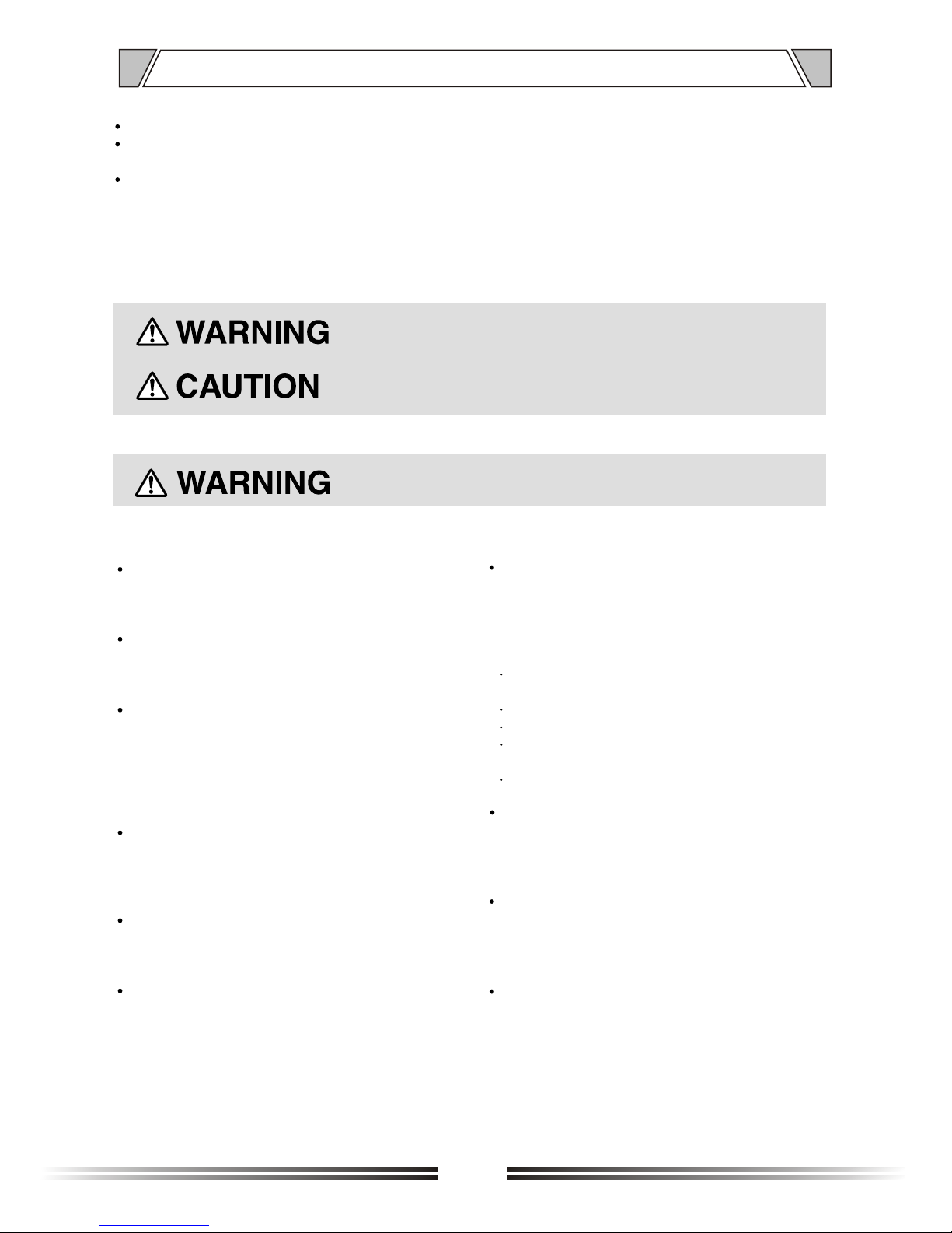
5. NOMENCLATURE AND FUNCTIONS
5.1 FRONT PANEL
1. MIC1 Volume Control
2. MIC1 treble adjustment
The treble response, clockwise rotation,
MIC1 increase treble output , whereas
reduced.
3. MIC1 bass tone adjustment
Adjust the bass response , clockwise
rotation, MIC1 increase treble output,
whereas reduced.
4. MIC2 Volume Control
5. MIC2 treble adjustment
6. MIC2 bass adjustment
7. Line channels selector
8. Line volume control
9. Line treble control
10. Line bass control
11. Left and Right volume control
12. Left channel control
13. Left channel level indicator
14. Right channel level indicator
15. Power Switch
16. Power LED (Blue)
2
7
1
13
3
5
4
6
98 10
1211 14
15 16
+3
0 -3 -8
-13
OUTPUT LEVEL
POWER
MIC 1
LEVEL TREBLE BASS
MIC 2
LEVEL TREBLE BASS
MUSIC
LEVEL
TREBLE BASS
SOURCE
PROJECT
MIX241
LEFT
RIGHT
MASTER
6
Page 7

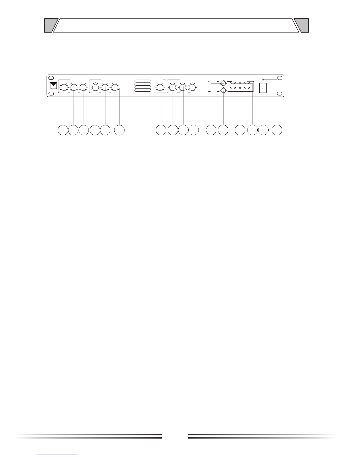
NOMENCLATURE AND FUNCTIONS
5.2 REAR PANEL
22. MIC (1 ~ 2) +48 V phantom power dial
the code Switch and priority function
control
23. MIC (1 ~ 2) phantom microphone input
24. MIC (1 ~ 2) GAIN gain adjustment
25. MIC (1-2) output switch
26. LINE (1 ~ 4) GAIN gain adjustment
17. ~ 230V 50Hz power input
18. Left and right channel line outputs
(XLR)
19. Left and right channel audio input
(REC)
20. Line input (LINE1 ~ LINE4)
21. Alarm signal input circuit
17
18
19
20
21
22
23
24
26 25
INPUTS
MIC 1MIC 2
2
1
3
OUTP UTS
REC
LINE 2
LINE 1
GAIN
LINE 4
LINE 3
GAINGAIN
ALARM
RIGHT
LEFT
GAIN
USE ONLY WITHA 250W FUSE
1 2 3 4
ON
12
3
12
3
VOLTAGE SELECTOR
MIC
LINE
GAIN
MIC
LINE
GAIN
1 2
3
RI GHT
MIC1 PRIORITY
MIC2 PRIORITY
MIC2 +48V PHANTOM
1
2
3
4
MIC1 +48V PHANTOM
1
234
LE FT
0.775V/600 0.775V/600
4mV-45mV/600 4mV-45mV/600
125mV-1.2V
10k
125mV-1.2V
10k
125mV-1.2V
10k
125mV-1.2V
10k
7
Page 8

6.OPERATION ILLUSTRATION
6.1
6.2
Power LED
Power switch
Figure 6.1/6.2
Note:
In order to work properly, equipment must be confirmed in a normal power state. If the machinefails,
please contact the vendor.
Figure 6.3
Note:
When used it, must use the security power input within the stipulated scope, avoid causingaccidents.
Power is to provide energy to equipment, must be safe use of power supply, don't use it, please pull power
6.3 Power Input
When the power switch to "ON" , power light becomes blue.
When the power switch to "OFF" , power light extinguish.
15
17
+3
0 -3 -8
POWER
ON
OFF
+3
0 -3 -8
-13
OUTPUT LEVEL
POWER
MIC 1
LEVEL TREBLE BASS
MIC 2
LEVEL TREBLE BASS
MUSIC
LEVEL
TREBLE BASS
SOURCE
LEFT
RIGHT
MASTER
INPUTS
MIC 1MIC 2
2 1
3
OUTPUTS
REC
LINE 2
LINE 1
GAIN
LINE 4
LINE 3
GAINGAIN
ALARM
RIGHT
LEFT
GAIN
USE ONLY WITHA 250W FUSE
1 2 3 4
ON
12
3123
VOLTAGE SELECTOR
MIC
LINE
GAIN
MIC
LINE
GAIN
1 2
3
RIGHT
MIC1 PRIORITY
MIC2 PRIORITY
MIC2 +48V PHANTOM
1
2
3
4
MIC1 +48V PHANTOM
1
234
LEFT
0.775V/600 0.775V/600
4mV-45mV/600 4mV-45mV/600
125mV-1.2V
10k
125mV-1.2V
10k
125mV-1.2V
10k
125mV-1.2V
10k
INPUT S
M IC 1MIC 2
2
1
3
OUTPUTS
REC
LINE 2
LINE 1
GAIN
LINE 4
LINE 3
GAINGAIN
ALARM
RIGHT
LEFT
GAIN
USE ONLY WITHA 250W FUSE
1 2 3 4
ON
12
3123
VOLTAGE SELECTOR
MIC
LINE
GAIN
MIC
LINE
GAIN
1 2
3
RIGH T
MIC1 PRIORITY
MIC2 PRIORITY
MIC2 +48V PHANTOM
1
2
3
4
MIC1 +48V PHANTOM
1234
LEFT
0.775V/600 0.775V/600
4mV-45mV/600 4mV-45mV/600
125mV-1.2V
10k
125mV-1.2V
10k
125mV-1.2V
10k
125mV-1.2V
10k
8
Page 9

6.OPERATION ILLUSTRATION
6.5
REC audio input interface
180 3-pole XLR
1.Ground pin
2.The hot end of the foot signal (positive)
3.The cold end of the foot signal (negative)
12
3
6.4
Left and Right channel line output jack about (XLR)
L/R OUTPUT
L / R OUTPUT line out, two channel selectable. All output should be connected to the Karon
jack on the rear panel of the machine.Volume control is done by the left and right volume knobs and each
with a row of signal lights, can understand the level of the signal outputs. This feature allows pure power
amp to work as pre-amplifier with the extensions amplifier feature.
Note:
L / R OUTPUT line out, you must first volume to mid-range position, to avoid the sound exposur
Figure 6.4
Figure 6.5
REC recording deck input interface, Left and right channel selectable. REC audio input interfaces to deck machine
Note:
1.
When REC inputs, you must first volume to mid-range position, to avoid the sound exposure
18
INPUTS
MIC 1MIC 2
2 1
3
OUTPUTS
REC
LINE 2
LINE 1
GAIN
LINE 4
LINE 3
GAINGAIN
ALARM
RIGHT
LEFT
GAIN
1 2 3 4
ON
12
3123
MIC
LINE
GAIN
MIC
LINE
GAIN
1 2
3
RIGHT
MIC1 PRIORITY
MIC2 PRIORITY
MIC2 +48V PHANTOM
1
2
3
4
MIC1 +48V PHANTOM
1
234
LEFT
0.775V/600 0.775V/600
4mV-45mV/600 4mV-45mV/600
125mV-1.2V
10k
125mV-1.2V
10k
125mV-1.2V
10k
125mV-1.2V
10k
ON
OFF
POWER
CLIP
OL
VOLUME
PROT
5
0
1
2
3
4 6
7
8
9
10
350-WATT AMPLIFIER
SIGNAL
19
CARD HOLDER
INPUTS
MIC 1MIC 2
2 1
3
OUTPUTS
REC
LINE 2
LINE 1
GAIN
LINE 4
LINE 3
GAINGAIN
ALARM
RIGHT
LEFT
GAIN
1 2 3 4
ON
12
3123
MIC
LINE
GAIN
MIC
LINE
GAIN
1 2
3
MIC1 PRIORITY
MIC2 PRIORITY
MIC2 +48V PHANTOM
1
2
3
4
MIC1 +48V PHANTOM
1
234
LEFT
4mV-45mV/600 4mV-45mV/600
125mV-1.2V
10k
125mV-1.2V
10k
125mV-1.2V
10k
125mV-1.2V
10k
INPUTS
MIC 1MIC 2
2
1
3
OUTPUTS
REC
LINE 2
LINE 1
GAIN
LINE 4
LINE 3
GAINGAIN
ALARM
RIGHT
LEFT
GAIN
USE ONLY WITHA 250W FUSE
1 2 3 4
ON
12
3123
VOLTAGE SELECTOR
MIC
LINE
GAIN
MIC
LINE
GAIN
1 2
3
RIGH T
MIC1 PRIORITY
MIC2 PRIORITY
MIC2 +48V PHANTOM
1
2
3
4
MIC1 +48V PHANTOM
1234
LEFT
0.775V/600 0.775V/600
4mV-45mV/600 4mV-45mV/600
125mV-1.2V
10k
125mV-1.2V
10k
125mV-1.2V
10k
125mV-1.2V
10k
9
Page 10

6.OPERATION ILLUSTRATION
6.6
LINE(1~4) Line Inputs
6.7
Alarm signal input circuit
Figure 6.6
LINE (1 ~ 4) line input , adjustable L (1 ~ 4) switches, and control the LINE (1 ~ 4) line inputs. Line input signal
can be adjusted by the volume knobs and the BASS/TREBLE control. At the same time, LINE (1 ~ 4) line input,
you can adjust the GAIN volume. By adjusting the GAIN size, You can control the input gain between 20 ~ 0dB.
LIN (1 ~ 4) line in the formula audio line input for connecting CD/MP3/TUNER equipment running
Note:
1.
2.
When using the line input, you must first volume to mid-range position, to avoid the sound exposure
Please avoid multiple audio input at the same time, or it will cause noise
Figure 6.7
Alarm signal input circuit, when the circuit is disconnected and closed signal, alarm will be triggered.The
volume of the alarm depends on the input level.
Note:
1.
Please turn the volume to mid-range position, to avoid the sound exposure
20
POWER
CD PLAYER
ON
OFF
PLAY STOP NEXTPREVIOUS
OPEN
CLOSE
CD
POWER
AM/FM TUNER
ON
OFF
BAND AUTO TUNING
TUNER
21
STANDBY
POWER
ALARM MODE
PLAY
RECORD
VOL
START STOP
REC
PLAY
SIREN
PLAY
MSG
LINE
MIC
ON
OFF
ALARMING SIGNAL GENERATOR
ALARMING SIGNAL GENERATOR
INPUTS
MIC 1MIC 2
2 1
3
LINE 2
LINE 1
ALARM
GAIN
1 2 3 4
ON
12
3123
MIC
LINE
GAIN
MIC
LINE
GAIN
MIC1 PRIORITY
MIC2 PRIORITY
MIC2 +48V PHANTOM
1
2
3
4
MIC1 +48V PHANTOM
1
234
4mV-45mV/600 4mV-45mV/600
125mV-1.2V
10k
INPUTS
MIC 1MIC 2
2
1
3
OUTPUTS
REC
LINE 2
LINE 1
GAIN
LINE 4
LINE 3
GAINGAIN
ALARM
RIGHT
LEFT
GAIN
USE ONLY WITHA 250W FUSE
1 2 3 4
ON
12
3123
VOLTAGE SELECTOR
MIC
LINE
GAIN
MIC
LINE
GAIN
1 2
3
RIGH T
MIC1 PRIORITY
MIC2 PRIORITY
MIC2 +48V PHANTOM
1
2
3
4
MIC1 +48V PHANTOM
1234
LEFT
0.775V/600 0.775V/600
4mV-45mV/600 4mV-45mV/600
125mV-1.2V
10k
125mV-1.2V
10k
125mV-1.2V
10k
125mV-1.2V
10k
10
Page 11

6.OPERATION ILLUSTRATION
6.8
MIC 1/MIC 2 balanced microphone input and Stubbs address code switch
Figure 6.8
MIC 1/MIC 2 balanced microphone input, volume size is determined by the panel MIC 1/MIC 2 knob control,
combined with BASS / TREBLE adjust the volume knob to achieve the desired acoustic effect.MIC 1/MIC 2
Use a balanced microphone input, adjustable phantom address priorities and can be manually controlled.
When the address code (1,2) switch, open the"1" address code, means the MIC 1 has priority over MIC2 and
LINE inputs 1-4 input. Open the "2" address code, means MIC 2 has priority over MIC1. When the +48 phan
-tom power address code (3,4) switch, open the "3" address code, said the MIC 2 balanced microphone with
power supply to the dynamic microphones;; when the +48 phantom switch, open the "4" address code, MIC 2
balanced microphone without power supply to the dynamic microphones.Besides, MIC (1 ~ 2) the hasthe gain
control. GAIN contol is between 20 ~ 60dB.
Note:
1.
2.
3.
When using the microphone input, you must first volume to mid-range position, to avoid sending the
sound exposure.
Microphone input priority must first adjust address code. Otherwise, the priority can not be controlled
Must ensure that the microphone is fully inserted, otherwise the call function can not be achieved
MIC 2
MIC 1
22 23
INPUTS
MIC 1MIC 2
2 1
3
ALARM
GAIN
1 2 3 4
ON
12
3123
MIC
LINE
GAIN
MIC
LINE
GAIN
MIC1 PRIORITY
MIC2 PRIORITY
MIC2 +48V PHANTOM
1
2
3
4
MIC1 +48V PHANTOM
1
234
4mV-45mV/600 4mV-45mV/600
125mV-1.2V
10k
INPUTS
MIC 1MIC 2
2
1
3
OUTPUTS
REC
LINE 2
LINE 1
GAIN
LINE 4
LINE 3
GAINGAIN
ALARM
RIGHT
LEFT
GAIN
USE ONLY WITHA 250W FUSE
1 2 3 4
ON
12
3123
VOLTAGE SELECTOR
MIC
LINE
GAIN
MIC
LINE
GAIN
1 2
3
RIGH T
MIC1 PRIORITY
MIC2 PRIORITY
MIC2 +48V PHANTOM
1
2
3
4
MIC1 +48V PHANTOM
1234
LEFT
0.775V/600 0.775V/600
4mV-45mV/600 4mV-45mV/600
125mV-1.2V
10k
125mV-1.2V
10k
125mV-1.2V
10k
125mV-1.2V
10k
11
Page 12

12
7.EQUIPMENT INNER DRAWING
Transforma
Audio PCB Board
Power Input
Panels
Power switch
audo PCB board
8. INSTALLATION STEPS
1. Firstly, install board inside the machine with wiring.
2. After install the back panel and floor with screws.
3. Then install equipment panel.
4. Finally, to install cover.
Note:
1.the equipment adopts 4X4mm screws. 2.when installation, keep equipment clean.
3.Undertake certain temperature conditions, installing equipment.
1
4
2
3
INPUTS
MIC 1MIC 2
2
1
3
OUTPUTS
REC
LINE 2
LINE 1
GAIN
LINE 4
LINE 3
GAINGAIN
ALARM
RIGHT
LEFT
GAIN
USE ONLY WITHA 250W FUSE
12 34
ON
12312
3
VOLTAGE SELECTOR
MIC
LINE
GAIN
MIC
LINE
GAIN
1 2
3
RIGHT
MIC1 PRIORITY
MIC2 PRIORITY
MIC2 +48V PHANTOM
1
2
3
4
MIC1 +48V PHANTOM
1234
LEFT
0.775V/600 0.775V/600
4mV-45mV/600 4mV-45mV/600
125mV-1.2V
10k
125mV-1.2V
10k
125mV-1.2V
10k
125mV-1.2V
10k
+3
0 -3 -8
-13
OUTPUT LEVEL
POWER
MIC 1
LEVEL TREBLE BASS
MIC 2
LEVEL TREBLE BASS
MUSIC
LEVEL
TREBLE BASS
SOURCE
LEFT
RIGHT
MASTER
Page 13

9.CONNECTION DIAGRAM
5
0
1
2
3
4 6
7
8
9
10
Mixer or Short
-circuit Plug
350-WATT AMPLIFIER
CD + TUNER PLAYER
2-CHANNEL AMPLIFIER
Podium Microphone
REMOTE
AM/FM DTS TUNER
PREV
NEXT
USB/CD
EJECT PLAY STOP
PLAY
MODE
MUTE
SD
USB
UP
6
AUTO/
MANUAL
5
4
MEM
3
ST/MON
AM/FM
2
1
DOWN
POWER
CD PLAYER
IR STATUS
REMOTE
AM/FM DTS TUNER
PREV
NEXT
USB/CD
EJECT PLAY STOP
PLAY
MODE
MUTE
SD
USB
UP
6
AUTO/
MANUAL
5
4
MEM
3
ST/MON
AM/FM
2
1
DOWN
POWER
CD PLAYER
IR STATUS
POWER
CH 2
VOLUME
ON
CH 1
VOLUME
MIN MAX
MIN MAX
CLIP
PROT
SIGNALCLIP
PROT
SIGNAL
CH 1
CH 2
CD + TUNER PLAYER
INPUTS
MIC 1MIC 2
2
1
3
OUTP UTS
REC
LINE 2
LINE 1
GAIN
LINE 4
LINE 3
GAINGAIN
ALARM
RIGHT
LEFT
GAIN
USE ONLY WITHA 250W FUSE
1 2 3 4
ON
12
3
12
3
VOLTAGE SELECTOR
MIC
LINE
GAIN
MIC
LINE
GAIN
1 2
3
RI GHT
MIC1 PRIORITY
MIC2 PRIORITY
MIC2 +48V PHANTOM
1
2
3
4
MIC1 +48V PHANTOM
1
2
3
4
LE FT
0.775V/600 0.775V/600
4mV-45mV/600 4mV-45mV/600
125mV-1.2V
10k
125mV-1.2V
10k
125mV-1.2V
10k
125mV-1.2V
10k
Podium Microphone
13
Page 14

10. BLOCK DIAGRAM
LINE1
LINE2
LINE3
LINE4
MIC1
MIC2
AMP
AMP
AMP
AMP
AMP
AMP
LOW
LOW
LOW
HIGH
HIGH
HIGH
SW
PH
L1
L2
L3
L4
PH
VOL
VOL
GAIN
GAIN
GAIN
GAIN
GAIN
GAIN
VOL
L
L/R
L/R
L/R
L/R
R
ALARM
REC OUT
LEVEL
R OUTPUT
PEAKSIG
LEVEL
L OUTPUT
PEAKSIG
TRIG
14
Page 15

11. SPECIFICATIONS
NET WEIGHT
Balanced Zone Outputs
Minimum load impedance
Maximum output level
Power input
Fuse rating
Dimensions
MODEL
LINE1-4 INPUTSLINE1-4 INPUTS
PROJECTMIX241
Frequency Response
Distortion
Sensitivity
Input Gain Control
Input Impedance
Noise
Equalisation
Frequency Response
Distortion
Gain Range
Input Impedance
Phantom power
Equalisation
Microphone1-2 Inputs
Noise
REC output level
Outputs
ELSE
>2k (balanced)
+15V (PCB jumper for on/off)
TREBLE: 10dB/5kHz BASS: 10dB/100Hz
-65dB A weighted
775mV (0dBu) 3 pin 'Phoenix' type connector
+20dBu (7.75V)
600 ohms
-12dBu (200MV)
230V 10% AC 50Hz
Z8: 230V T125mA H 115V T250mA H
484mm x 300mmx44mm(1U)
195mV (-12dBu) to 2.0V (+8dBu)
20Hz-20kHz 0.5dB
20dB range
<0.05% 20Hz -20kHz
-90dB A weighted (0dB gain)
TREBLE: 10dB/10kHz BASS: 10dB/100Hz
10dB-50dB
<0.05% 20Hz-20kHz
100Hz / -3dB(filter) 20kHz 0.5dB
47k
3.9Kg
15
(Specific voltage and frequency values to the machine to prevail in kind.)
Page 16

Over 100
More than100
Over 100
UNIT:mm
3
44
41
315
295
45
48
436
484
12. DIMENSIONAL DIAGRAM
INPUTS
MIC 1MIC 2
2 1
3
OUTPUTS
REC
LINE 2
LINE 1
GAIN
LINE 4
LINE 3
GAINGAIN
ALARM
RIGHT
LEFT
GAIN
USE ONLY WITHA 250W FUSE
1 2 3 4
ON
12
3
12
3
VOLTAGE SELECTOR
MIC
LINE
GAIN
MIC
LINE
GAIN
1 2
3
RIGHT
MIC1 PRIORITY
MIC2 PRIORITY
MIC2 +48V PHANTOM
1
2
3
4
MIC1 +48V PHANTOM
1
234
LEFT
0.775V/600 0.775V/600
4mV-45mV/600 4mV-45mV/600
125mV-1.2V
10k
125mV-1.2V
10k
125mV-1.2V
10k
125mV-1.2V
10k
UNIT:mm
+3
0 -3 -8
-13
OUTPUT LEVEL
POWER
MIC 1
LEVEL TREBLE BASS
MIC 2
LEVEL TREBLE BASS
MUSIC
LEVEL
TREBLE BASS
SOURCE
PROJECT
MIX241
LEFT
RIGHT
MASTER
+3
0 -3 -8
-13
OUTPUT LEVEL
POWER
MIC 1
LEVEL TREBLE BASS
MIC 2
LEVEL TREBLE BASS
MUSIC
LEVEL
TREBLE BASS
SOURCE
PROJECT
MIX241
LEFT
RIGHT
MASTER
16
Page 17

VersionV0.1
 Loading...