

Page 1
Please follow the instructions in this manual to obtain the optimum results from this unit.
We also recommend that you keep this manual handy for future reference.
OPERATION MANUAL
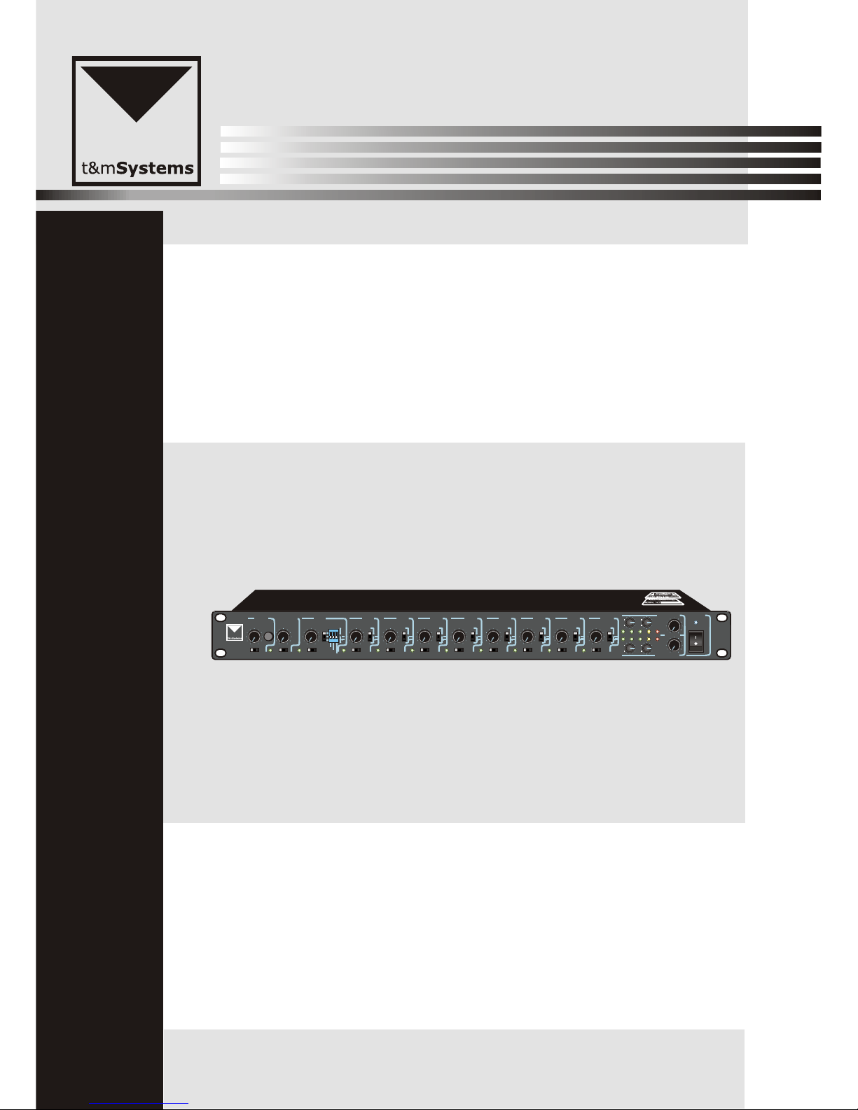
ProjectMix10
PROJECTMix10
CH 4 CH 5 CH 6 CH 7
CH 8
CH 9 CH 10
CHIME
POWER
CH 2
-PAGEMIC 1
CH 3
MASTER 1
1 1+2 2 1 1+2 2 1 1+2 2 1 1+2 2 1 1+2 2
1 1+2 2
1 1+2 2 1 1+2 2 1 1+2 2 1 1+ 2 2 1 1+2 2
SIGNAL SIGNAL SIGNAL SIGNAL SIGNAL SIGNAL SIGNAL SIGNAL SIGNAL SIGNAL
OUTPUT OUTPUT OUTPUT OUTPUT OUTPUT OUTPUT OUTPUT OUTPUT OUTPUT OUTPUT OUTPUT
LEVEL LEVEL LEVEL LEVEL LEVEL LEVEL LEVEL LEVEL LEVEL LEVEL LEVEL
PRIORITY2
PRIORITY3
PRIORITY4
LINE
MIC
LINE
MIC
LINE
MIC
LINE
MIC
LINE
MIC
LINE
MIC
LINE
MIC
LINE
MIC
LINE
MIC
+3 0 -3
-8
-13
LOW
HIGH
HIGH
MASTER 2
VOLUME
LOW
00
0000
ON
1
2
3
Page 2

TABLE OF CONTENTS
ProjectMix10
2
1. SAFETY PRECAUTIONS .......................................................................................3
2. GENERAL DESCRIPTION ....................................................................................5
3. FEATURES ...............................................................................................................5
4. NOMENCLATURE AND FUNCTIONS
4.1 Front Panel .............................................................................................................6
4.2 Rear Panel............................................................................................................. 7
5. APPLICATIONS ......................................................................................................8
6.SPECIFICATIONS ................................................................................................. 9
7.BLOCK DIAGRAM ................................................................................................. 10
8.DIMENSIONAL DIAGRAM ....................................................................................11
V1.0-09-11-27
Page 3
Be sure to read the instructions in this section carefully before use.
Make sure to observe the instructions in this manual as the conventions of safety symbols and messages
regarded as very important precautions are included.
We also recommend you keep this instruction manual handy for future reference.
Safety Symbol and Message Conventions
Safety symbols and messages described below are used in this manual to prevent bodily injury and property
damage which could result from mishandling. Before operating your product, read this manual first and
understand the safety symbols and messages so you are thoroughly aware of the potential safety
Indicates a potentially hazardous situation which, if mishandled, could
result in death or serious personal injury.
Indicates a potentially hazardous situation which, if mishandled, could
result in moderate or minor personal injury, and/or property damage.
When Installing the Unit
Do not expose the unit to rain or an environment
where it may be splashed by water or other liquids,
as doing so may result in fire or electric shock.
Use the unit only with the voltage specified on the
unit. Using a voltage higher than that which is
specified may result in fire or electric shock.
Do not cut, kink, otherwise damage nor modify the
power supply cord. In addition, avoid using the
power cord in close proximity to heaters, and never
place heavy objects -- including the unit itself -- on
the power cord, as doing so may result in fire or
electric shock.
Be sure to replace the unit's terminal cover after
connection completion. Because high voltage is
applied to the speaker terminals, never touch these
terminals to avoid electric shock.
Be sure to ground to the safety ground (earth)
terminal to avoid electric shock. Never ground to a
gas pipe as a catastrophic disaster may result.
Avoid installing or mounting the unit in unstable
locations, such as on a rickety table or a slanted
surface. Doing so may result in the unit falling
down, causing personal injury and/or property
damage.
When the Unit is in Use
Should the following irregularity be found during
use, immediately switch off the power, disconnect
the power supply plug from the AC outlet and
contact your nearest dealer. Make no
further attempt to operate the unit in this condition
as this may cause fire or electric shock.
If you detect smoke or a strange smell coming
from the unit.
If water or any metallic object gets into the unit
If the unit falls, or the unit case breaks
If the power supply cord is damaged (exposure of
the core, disconnection, etc.)
If it is malfunctioning (no tone sounds.)
To prevent a fire or electric shock, never open nor
remove the unit case as there are high voltage
components inside the unit. Refer all servicing to
your nearest dealer.
t&mSystems
t&mSystems
Do not place cups, bowls, or other containers of
liquid or metallic objects on top of the unit. If they
accidentally spill into the unit, this may cause a fire
or electric shock.
Do not insert nor drop metallic objects or
flammable materials in the ventilation slots of the
unit's cover, as this may result in fire or electric
shock.
3
1. SAFETY PRECAUTIONS
ProjectMix10
Page 4

An all-pole mains switch with a contact separation of at least 3 mm in each pole shall be incorporated in
the electrical installation of the building.
When Installing the Unit
Never plug in nor remove the power supply plug
with wet hands, as doing so may cause electric
shock.
When unplugging the power supply cord, be sure
to grasp the power supply plug; never pull on the
cord itself. Operating the unit with a damaged
power supply cord may cause a fire or electric
shock.
When moving the unit, be sure to remove its power
supply cord from the wall outlet. Moving the unit
with the power cord connected to the outlet may
cause damage to the power cord, resulting in fire or
electric shock. When removing the power cord, be
sure to hold its plug to pull.
Do not block the ventilation slots in the unit's cover.
Doing so may cause heat to build up inside the unit
and result in fire.
Avoid installing the unit in humid or dusty locations,
in locations exposed to the direct sunlight, near the
heaters, or in locations generating sooty smoke or
steam as doing otherwise may result in fire or
electric shock.
When the Unit is in Use
Do not place heavy objects on the unit as this may
cause it to fall or break which may result in
personal injury and/or property damage. In
addition, the object itself may fall off and cause
injury and/or damage.
Make sure that the volume control is set to
minimum position before power is switched on.
Loud noise produced at high volume when power is
switched on can impair hearing.
Do not operate the unit for an extended period of
time with the sound distorting. This is an indication
of a malfunction, which in turn can cause heat to
generate and result in a fire.
Contact your dealer as to the cleaning.
If dust is allowed to accumulate in the unit over a
long period of time, a fire or damage to the unit
may result.
t&mSystems
If dust accumulates on the power supply plug or in
the wall AC outlet, a fire may result. Clean it
periodically. In addition, insert the plug in the wall
outlet securely.
Switch off the power, and unplug the power supply
plug from the AC outlet for safety purposes when
cleaning or leaving the unit unused for 10 days or
more. Doing otherwise may cause a fire or electric
shock.
1. SAFETY PRECAUTIONS
4
ProjectMix10
Page 5

5
3. FEATURES
The ProjectMix10 series is equiped with pre-amplifier. They are designed to suit all PA system application in schools.
Home.offices and stores.
2. GENERAL DESCRIPTION
1. CHIME SIGNAL
1 Selective two tone/four tone chime(Internal setting)
2 Automatic priority
3 Permissible external chime remote and p.t.t remote
2. Master 1,2 output
3. Two band eq per output
4. Signal indicator per input
5. Independent din jack for p.t.t remote
6. Prioriyt switch and phantom of mic 2,3,4
7. Selective mic input of h.p.f
8. Selective output per input signal(output 1,output1+2,output 2)
9. Independent line input with rca pin jack (line 7~10)
10. Recording output
11. Led indicator for master-output
12. AC/DC 24V
ProjectMix10
Page 6

6
4. NOMENCLATURE AND FUNCTIONS
2
4.1 FRONT PANEL
1
4
5 6 7
1. CHIME
Pressing chime switch, chime signal
will be activated as a pre signal. You
can adjust level.
= OUTPUT SWITCH
This is for selector that send chime
signal to master output.Chime signal
has a priority .when chime signal is
activated, signal output of input 5~10
will be closed.
IMPORTANT NOTICE:Priority will be
given only for selected output.
2. INPUT1 CONTROLS
Adjust level volume so as not to turn
on +3CLIP LED under two~three o
clock of master volume this is control
For mic input level.
= OUTPUT SWITCH
This is selector that send signal of
input 1 to the master output.when
input 1 are activated , signal of input
5~10 will be closed.
3. INPUT 2,3,4 CONTROLS
Adjust level volume so as not to
turn on +3LED under two~three o
clock of master volume this is
control for MIC/LINE input closed.
= OUTPUT SWITCH
This is selector that send signal of
input 2,3,4 to the master output.
when input 2~4 are activated , signal
of input 5~10 will be closed.
= MODE SWITCH
MIC : It is input mic switch of 300Hz
H.P.F that makes sound
clearance.when you select
Switch , windy sound.
MIC : This is MIC input switch
Without filter line.
LINE : Line input for CD CASSETTE,
TUNER.
IMPORTANT NOTICE:Serecting
mode switch HPF
flat power will be supplied to
input XLR connector for condensor
mic only.If you connect unbalanced
dynamic microphone with them,it
May be defaulted and should be
moving to mode switch for noise
Down.
= PRIORITY 2~4
When you switch on , priority is
activated and will closed input 5~10.
4. INPUT 5~10 CONTROLS
These make adjustment of MIC/LINE
For input 5~10.
Adjust output level so as not to tune
on CLIP LED under two o clock.
= OUTPUT SWITCH
This is selector that send signal of
input 5~10 to the master-output.
When input 1~4 signal and chime
signal are supplied, priority will be
activated and close output of input
5~10.
This is selector that send signal of
input 2,3,4 to the master output
when input 2~4 are activated , signal
of input 5~10 will be close.
= MODE SWITCH
MIC : It is input mic switch of 300Hz
H.P.F that makes sound
clearance.when you select
Switch , windy sound.
MIC : This is MIC input switch
Without filter line.
LINE : Line input for CD CASSETTE,
TUNER.
IMPORTANT NOTICE:Serecting
mode switch HPF
flat power will be supplied to
input XLR connector for condensor
mic only.If you connect unbalanced
dynamic microphone with them,it
May be defaulted and should be
Minimized level volume before
moving to mode switch for noise
Down.
5. EQUALIZER
Adjust low, high if EQ volume
According to condition.
6. MAST 1,2
This is master volume for all input
levels you and better use toward two
o clock adjust level before clipping
for proper operation.
7. POWER SWITCH
Press to turn ON the power.
Press again to turn the power OFF.
3
ProjectMix10
ProjectMix10
PROJECTMix10
CH 4 CH 5 CH 6 CH 7
CH 8
CH 9 CH 10
CHIME
POWER
CH 2
-PAGEMIC 1
CH 3
MASTER 1
1 1+2 2 1 1+2 2 1 1+2 2 1 1+2 2 1 1+2 2
1 1+2 2
1 1+2 2 1 1+2 2 1 1+2 2 1 1+2 2 1 1+2 2
SIGNAL SIGNAL SIGNAL SIGNAL SIGNAL SIGNAL SIGNAL SIGNAL SIGNAL SIGNAL
OUTPUT OUTPUT OUTPUT OUTPUT OUTPUT OUTPUT OUTPUT OUTPUT OUTPUT OUTPUT OUTPUT
LEVEL LEVEL LEVEL LEVEL LEVEL LEVEL LEVEL LEVEL LEVEL LEVEL LEVEL
PRIORITY2
PRIORITY3
PRIORITY4
LINE
MIC
LINE
MIC
LINE
MIC
LINE
MIC
LINE
MIC
LINE
MIC
LINE
MIC
LINE
MIC
LINE
MIC
+3 0 -3
-8
-13
LOW
HIGH
HIGH
MASTER 2
VOLUME
LOW
00
00
Page 7

REC LINE 10
LINE 9
LINE 8
LINE 7
L
EF
T
RIGH
T
MIC INPUTS MIC INPUTS MIC/LINE INPUTSMIC/LINE INPUTS
P.T.T 1P.T.T 1
2 2
33
44
55
66
77
889 9
10 10
DC POWER
24V MAX 0.6A
PUBLIC ADDRESS SYSTEM
SERIAL NO:
CHIME
REMOTE
MODEL NO: ProjectMix10
PRE AMPLIFIER
2--OUTPUTS--1 2--OUTPUTS--1
12
3
12
3
12
3
12
3
12
3
12
3
12
3
12
3
12
3
INSIDE AC/DC
FUSE 230VAC
MAX 9.9W
230V/50Hz
~
7
4
5
2
4
2
GND
PRIORITY
CHIME
LED PWR
MIC INPUT
1
3
5
6
7
1
3
6
2 1
3
NOMENCLA TURE AND FUCTIONS
7
4.2 REAR PANEL
8 9 10 11
12 13 14 15
8. AC POWER
Be sure to check AC voltage. Use
fuse approved.
IMPORTANT NOTICE:Be sure not
to make a shorten for battery and
polarity of battery.
9. DC POWER
This is a connector unexpected AC
Failure.
Buit in fuse PCB Fu902(1TAL 250V)
IMPORTANT NOTICE:
FU901: 230V-F200mAL 250V
10.OUTPUTS 1,2
This is master outputs which can be
selected by switch.
11.RECORDING
Recording outputs two L, R
unbalanced RCA jacks are
converted into stereo signals in the
internal circuit from mono signal.
Recording output volume can not be
controlled by master volume
controller because circuit of
recording output controls is just in
the before master volume controls.
12.LINE 7~10
LINE 7~10 unbalanced two L, R
RCA jack are converted into mono
in the internal circuit all line input 10dB(245mV) input level are for
cassette deck, CD, dat deck, tuner.
13.MIC/LINE INPUT 2~6
MIC/LINE balanced input can be
selected by mode switch in the front
panel.
IMPORTAN NOTICE:
When you select MIC input,
operating voltage is only for
condensor microphone if you
connect dynamic microphone
balance by mistake, microphone
will be out of work also, be sure not
be insert mic input connector under
level volume-up, speaker systems
may get damage due to big noise.
14.P.T.T. 1
Connect this terminal with T-319
priority and chime controls are
activated from T-319(P.T.T remote)
and Microphone cable with shield
can be extended at the max 30m.
IMPORTAN NOTICE:
Be sure not to make a shorten to the
ground because microphone signal
+, -is for operating power of
condensor microphone.
15.CHIME REMOTE TERMINAL
This is a terminal for chime signal.
ProjectMix10
Page 8

5. APPLICATIONS
REAR PANEL CONNECTIONS
8
ProjectMix10
REC LINE 10
LINE 9
LINE 8
LINE 7
L
E
F
T
R
I
G
H
T
MIC INPUTS MIC INPUTS MIC/LINE INPUTSMIC/LINE INPUTS
P.T.T 1P.T.T 1
2 2
33
44
55
66
77
889 9
10 10
DC POWER
24V MAX 0.6A
PUBLIC ADDRESS SYSTEM
SERIAL NO:
CHIME
REMOTE
MODEL NO: ProjectMix10
PRE AMPLIFIER
2--OUTPUTS--1 2--OUTPUTS--1
12
3
12
3
12
3
12
3
12
3
12
3
12
3
12
3
12
3
INSIDE AC/DC
FUSE 230VAC
MAX 9.9W
230V/50Hz
~
7
4
5
2
4
2
GND
PRIORITY
CHIME
LED PWR
MIC INPUT
1
3
5
6
7
1
3
6
2 1
3
~230V 60Hz
T1AL250V
AUDIO
OUT
R
L
RISK OF ELECTRIC SHOCK
DO NOT OPEN
RISQUE DE CHOC ELECTRICUS
-NE PAS QUVRIR
AVIS:
PUBLIC ADDRESS SYSTEM
SERIAL NO:
AUDIO SOURCES
COM
ADRESS TAG
AUDIO SOURCES
MIC 6 MIC 2
MIC 10 MIC 7
MAINS ~230V 60Hz
FUSE T6AL250V
1
2
3
XLR BAL
INPUT
1-GND
2-HOT+
3-COLD-
POWER OUT2
¦¸¦¸
70V
50V
COM
4
100V
POWER OUT1
¦¸¦¸
70V
50V
COM
4
100V
CH2 INPUTSCH2 LINK CH1 LINK CH1 INPUTS
RISK OF ELECTRIC SHOCK
DO NOT OPEN
RISQUE DE CHOC ELECTRICUS
-NE PAS QUVRIR
AVIS:
PUBLIC ADDRESS SYSTEM
SERIAL NO:
AMPLIFIER
CASSETTE DECKS
DV 24V
Page 9

6. SPECIFICATIONS
MODEL
ProjectMix10
OUTPUT LEVEL/IMPEDANCE
INPUT SENSITIVITY/IMPEDANCE
FREQUENCY RESPONSE
Less Than -0.5dB(20Hz~20KHz)
DIMENSION(mm)
NET WEIGHT
GROSS WEIGHT
484X210X45
6.65Kg
5.52Kg
MIC/LINE: -5dBu(2.45mV)/5Kohms BAL
-10dBu(245mV)/5Kohms BAL
LINE RCA IN:-10dBu(245mV)/10Kohms UNBAL
MASTER 1,2:NOR +4dBu(21.23V)/200ohms BAL
REC: NOR 0dBu(0.775mV)/10K UNBAL
OUTPUT LEVEL/IMPEDANCE
MASTER 1,2:NOR +4dBu(21.23V)/200ohms BAL
REC: NOR 0dBu(0.775mV)/10K UNBAL
SIGNAL TO NOISE RATIO
MIC: MORE THAN 60dB
LINE: MORE THAN 0.03%
CROSS-TALK
MIC:MORE THAN 60dB
LINE:MORE THAN 75dB
POWER CONSUMPTION
POWER CONSUMPTION
13W
AC 230V 50Hz
DC 24V
9
ProjectMix10
Page 10

7. BLOCK DIAGRAM
10
ProjectMix10
3
5
Page 11

100
Over
100
Over
Over
100
8. DIMENSIONAL DIAGRAM
UNIT :mm
UNIT :mm
11
3
178
41
441
41
484
45
51
ProjectMix10
PROJECTMix10
CH 4 CH 5 CH 6 CH 7
CH 8
CH 9 CH 10
CHIME
POWER
CH 2
-PAGEMIC 1
CH 3
MASTER 1
1 1+2 2 1 1+2 2 1 1+2 2 1 1+2 2 1 1+ 2 2
1 1+2 2
1 1+2 2 1 1+2 2 1 1+2 2 1 1+2 2 1 1+2 2
SIGNAL SIGNAL SIGNAL SIGN AL SIGNAL SIGNAL SIGNAL SIGNAL SIGNAL SIGNAL
OUTPUT OUTPUT OUTPUT OUTPUT OUTPUT OUTPUT OUTPUT OUTPUT OUTPUT OUTPUT OUTPUT
LEVEL LEVEL LEVEL LEVEL LEVEL LEVEL LEVEL LEVEL LEVEL LEVEL LEVEL
PRIORITY2
PRIORITY3
PRIORITY4
LINE
MIC
LINE
MIC
LINE
MIC
LINE
MIC
LINE
MIC
LINE
MIC
LINE
MIC
LINE
MIC
LINE
MIC
+3 0 -3
-8
-13
LOW
HIGH
HIGH
MASTER 2
VOLUME
LOW
00
00
REC LINE 10
LINE 9
LINE 8
LINE 7
LEF
T
R
I
G
H
T
MIC INPUTS MIC INPUTS MIC/LINE INPUTSMIC/LINE INPUTS
P.T.T 1P.T.T 1
2 2
33
44
55
66
77
889 9
10 10
DC POWER
24V MAX 0.6A
PUBLIC ADDRESS SYSTEM
SERIAL NO:
CHIME
REMOTE
MODEL NO: ProjectMix10
PRE AMPLIFIER
2--OUTPUTS--1 2--OUTPUTS--1
12312312312312312312312312
3
INSIDE AC/DC
FUSE 230VAC
MAX 9.9W
230V/50Hz
~
7
4
5
2
4
2
GND
PRIORITY
CHIME
LED PWR
MIC INPUT
1
3
5
6
7
1
3
6
2 1
3
PROJECTMix10
CH 4 CH 5 CH 6 CH 7
CH 8
CH 9 CH 10
CHIME
POWER
CH 2
-PAGEMIC 1
CH 3
MASTER 1
1 1+2 2 1 1+2 2 1 1+2 2 1 1+2 2 1 1+2 2
1 1+2 2
1 1+2 2 1 1+ 2 2 1 1+2 2 1 1+2 2 1 1+2 2
SIGNAL SIGNAL SIGNAL SIGNAL SIGNAL SIGNAL SIGNAL SIGNAL SIGNAL SIGNAL
OUTPUT OUTPUT OUTPUT OUTPUT OUTPUT OUTPUT OUTPUT OUTPUT OUTPUT OUTPUT OUTPUT
LEVEL LEVEL LEVEL LEVEL LEVEL LEVEL LEVEL LEVEL LEVEL LEVEL LEVEL
PRIORITY2
PRIORITY3
PRIORITY4
LINE
MIC
LINE
MIC
LINE
MIC
LINE
MIC
LINE
MIC
LINE
MIC
LINE
MIC
LINE
MIC
LINE
MIC
+3 0 -3
-8
-13
LOW
HIGH
HIGH
MASTER 2
VOLUME
LOW
00
00
Page 12

PUBLIC ADDRESS SYSTEM
2009-11 Version1.0
 Loading...