

Page 1
䠄 䠅
Page 2

[SPECIFICATION]
*Refer to the 2pages for other Cal. No. specifications.
φ23.70 mm
22.60 mm : between 12 o'clock and 6 o'clock sides
22.60 mm : between 3 o'clock and 9 o'clock sides
φ23.30 mm
22.10 mm : between 12 o'clock and 6 o'clock sides
21.40 mm : between 3 o'clock and 9 o'clock sides
3.45 mm
Cal. No.
Electronic circuit reset switch
Second setting device
Date setting
Day : Retrogade
SR920SW (Silver oxide battery)
Battery life is approximately 2 years
Use 10-second gate
* Set the winding stem with crown at the normal position
* All specifications are subject to change without notice.
Day -Calendar
Hand (10H)
-
○
SII Products
Driving System
Step motor
Additional mechanism
Antimagnetic
≧1600 A/m
Accuracy
Less than ±15seconds : Monthly rate at normal temperature range
Battery
Measuring gate
by quartz tester
Jewels
2 Jewels
1
Date -Calendar
Hand (12H)
--○
-
Date -Calendar
Hand (3H)
○--
○
VH88A
3Hands
(hour,minute,second)
○
○
○
○
Time
indication
24Hour hand (6H)
Date -Calendar
Hand (2H)
Day -Calendar
Hand (9H)
PARTS CATALOGUE / TECHNICAL GUIDE
VH8 Series
Version-01
Cal. No.
VH83A
Item
Movement
Movement
size
Outside diameter
Casing diameter
Total height
VH83A
Page 3

2
SII Products
MOVEMENT VARIATION
Version-01
VH8A
VH88
VH83
date
24hours
day
date
24hours
day
Page 4
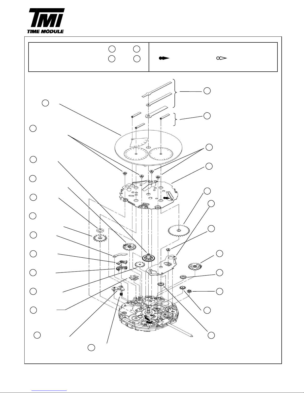
Disassembling procedures Figs. Lubricating : Types of oil Oil quantity
Reassembling procedures Figs.
Moebius A
Normal quantity
*Refer to the 6pages for the each parts code
Hour , Minute ,Second hands
Dial
Date-Day calendar,24Hour
hands
0012 354
4 0012 354
Support for dial side parts screw
0273 043
Hour wheel 5 0604 170 *
Support for dial side parts
0802 469
Day driving wheel
0970 004 Date Star
0491 014
Dial washer 0836 005 *
Intermediate wheel for date
0157 018 corrector holder
Small hour hand wheel
0012 354
0873 169 Intermediate wheel for date
Day jumper corrector holder screw
0585 169 0802 469
Hammer A Date driving wheel
0585 170 0962 033
Hammer B Intermediate wheel for
date corrector C
0817 049 0737 169
Intermediate hour wheel
Date corrector wheel
0505 169 0737 006
Day transmission wheel Intermediate wheel for
date corrector D
0125 324 0962 033
Day wheel bridge
Intermediate wheel for
1019 012 date corrector B
Day wheel
Version-01
VH8A
PARTS CATALOGUE
1⇒24
3
SII Products
24⇒1
1021241192023
22
Support for dial
side parts screw
14171819815161213
<<VH83A>>
124
3
6
7
Page 5

Disassembling procedures Figs. Lubricating : Types of oil Oil quantity
Reassembling procedures Figs.
Moebius A Normal quantity
*Refer to the 6pages for the each parts code
Hour , Minute ,Second hands
Dial
Date-Day calendar,24Hour
0012 354 hands
0012 354
Support for dial side parts screw
0273 043
Hour wheel 0604 160 *
Support for dial side parts
0802 469
Day driving wheel
0491 014
0970 004 Date Star
Dial washer
0836 006 *
0157 018 Intermediate wheel for date
Small hour hand corrector holder
wheel
0873 169 0012 354
Day jumper Intermediate wheel for date
corrector holder screw
0585 169
Hammer A 0802 469
Date driving wheel
0585 170 0804 170
Hammer B Intermediate wheel for
date corrector C
0125 324 0737 169
Day wheel bridge
Date corrector wheel
1019 012 0737 006
Day wheel
Intermediate wheel for
date corrector D
0962 033
0505 169 Intermediate wheel for
Day transmission wheel date corrector B
⇒
1
3
Version-01
VH8A
PARTS CATALOGUE
1⇒23
23
124520
4
SII Products
1314212312111516179221910
4
Support for dial
side parts screw
18
7
6
8
Page 6

Disassembling procedures Figs. Lubricating : Types of oil Oil quantity
Reassembling procedures Figs.
Moebius A
Normal quantity
Moebius F
Liberal quantity
*Refer to the 6pages for the each parts code
*Battery connection(+)
0351 177
27⇒1
PARTS CATALOGUE
Version-01
VH8A
1⇒2798111273
14
SII Products
1351517212061618
19
2 0012 168
Battery connection (+) screw
3 4268 076 *
Battery connection(+)
4 4216 103
Insulator
7 0144 004
Fourth wheel and pinion
8 0560 005
Friction spring for
fourth wheel and pinion
14 0281 015
Setting wheel
16 0261 052
Minute wheel
and pinion
25 0012 354
Center wheel
bridge screw
27 0221 089 *1
Center wheel
and pinion
23 4002 070
Coil block
5 4270 339
Battery
connection(-)
6 0125 321
Train wheel bridge
10 0701 017
Fifth wheel and pinion
15 0391 029
Train wheel
setting lever
17 0383 891
Setting lever
18 0384 452
Yoke
20 0282 452
Clutch wheel
21 0804 169
Intermediate wheel for
date corrector A
19 0351 177
Winding stem
13 4004 474
Circuit block
11 0706 008
Sixth wheel and pinion
9 0231 061
Third wheel and pinion
12 4146 104
Step rotor
26 0121 060
Center wheel bridge
24 4239 065
Stator
22 0012 354
Coil block screw
*1
Main plate
1 Battery
Page 7

Remarks:
Different parts for each CAL.
* All parts code are subject to change without notice.
PARTS CATALOGUE
Version-01
VH8A
Parts name
Parts code
VH83A
VH88A
Battery connection(+)
4268 076
O
―
4268 078―O
Intermediate wheel for
date corrector C
0962 033
O
―
0804 170―O
Intermediate wheel for
date corrector holder
0836 005
O
―
0836 006―O
SII Products
6
Support for dial side parts
0604 017
O
―
0604 016―O
Page 8

・The explanation here is only for the particular point of Cal.VH8A
1.REMARKS ON DISASSEMBLING AND REASSEMBLING
(1) Day wheel
・How to install:
①Set Lever of Hammer A along the pin of the main plate.
②After confirm that gears of Hammer A and B are engaged each other, set Day wheel vertically.
【VH83】
【Hammer A 】
(2)HAND
・How to install hands:
Place the movement directly on a flat metal plate
or such a hard plate when you install the hands.
Necessary procedure to setting hands:
①The state of movement is confirmed by the position of
a right picture.
Day transmission wheel
Pull out the crown to the second click position and
rotate to set the position of Day transmission wheel
and Support for dial side parts.
②Set the dial.
③Install the date calendar hand at the 12 o'clock position.
④Install the Day calendar hand at the first position.
⑤Pull out the crown to the second click position,
and change the date by rotating the crown clockwise.
⑥Install the 24hour, hour, minute and second hands
at the 12 o'clock position.
Necessary procedure to setting hands:
(3)Day calendar (Retrograde) hand
first position
・Quick moving of Day calendar hand
The hand instantaneously returns from B position
to A position when one week passes.
TECHNICAL GUIDE
Version-01
VH8A
SII Products
7
Support for dial side parts
Direction of rotation
Metal plate
B position
A position
Lever
Pin of the
Main plate
Day
Page 9

(4)Winding stem
・How to remove:
Pull out the winding stem while pushing
the indented portion of the arrow.
(5)Battery
・How to install:
Insert the battery in the aslant direction as shown by the arrow.
Check that the battery connection (+) touches securely
the side face of the battery.
・How to remove:
Firstly slide the battery in the direction of the arrow with
tweezers,and then lift the battery.
(6)Insulator
・How to set:
To insulate between the battery connection (+)
and the battery connection (-), the insulator
should be put at the two pins securely as bellow.
(7)Day jumper and Support for dial side parts
・Reassembling procedures
The support for dial side parts spring sets to the
day jumper. (A position)
Day jumper
Support for dial side parts spring
A position
TECHNICAL GUIDE
Version-01
VH8A
SII Products
8
Insulator
Pin
Push
Page 10

(8)Setting position (at the time of disassembling and reassembling)
・How to set the Date & Day driving wheels in the correct position:
Note:
Set the indicator finger of a Date & Day driving wheels to the setting position mark on the Main plate.
≪Cal.VH83A setting position≫ ≪Cal.VH88A setting position≫
Indicator finger
Setting position
SII Products
9
TECHNICAL GUIDE
Version-01
VH8A
Setting position
Setting position
Indicator finger
Date driving wheel
Indicator finger
Day driving
wheel
Enlargement
Enlargement
Page 11

・How to assemble and set the Date & Day jumpers of the support of dial side parts:
There are two hooks on the support for dial side parts. (Fig.1)
First, assemble the two hooks on the support for dial side parts
to the position of the built-in height A of the base plate. (Fig.2)
Set the Date & Day jumper to the teeth of the Date star & Day wheel.
Second,assemble the two hooks on the position of the built-in height B of the base plate. (Fig.3)
example VH83A
Fig.1 (example VH83A)
Fig.2 (built-in height A) Fig.3 (built-in height B)
TECHNICAL GUIDE
Version-01
VH8A
SII Products
10
height A position
height B position
Page 12

*1: Hour hand
*4:
Date calendar hand
*7:
Crown at normal position *9: Second click
*2:
Minute hand
*5:
Day calendar hand
*8:
First click
・Time setting
*3:
Second hand
*6:
24Hour hand
・Date setting (Quick change function)
1.Pull out the crown to the 2.Push the crown back 3.Pull out the crown to 4.Push the crown back
second click when the into the normal position the first clik. into the normal position.
second hand is at the
in signal. Turn the crown counter-
12 O'clock position.
clockwise to set the date.
Turn the crown rotation to
set the day of the week.
Turn the crown to set the
hour and minute hands
to the time.
(Check that AM / PM is
set correctly)
*Do not set the date between 10:00 PM and 2:00 AM
Otherwise the day could not change properly. If it is necessary to set the date during that time period,
once change the time to any time except the period, and then set the date.
After that set the time correctly.
Notes in time setting of Cal.VH8 series
When time setting is done with counterclokwise, date hand might reverse but there is no problem
for the function.
Please set the date by using quick change function when date showing is incorrect.
OPERATION
Version-01
VH8A
DISPLAY AND CROWN OPERATION
≪VH83A≫
≪VH88A≫
SII Products
11
TIME SETTING
Note:
*4
*7
*8
*9
*5
*1
*3
*6
*2
*1
*5
*3
*6
*2
*7
*8
*9
*4
 Loading...