

Page 1

Page 2
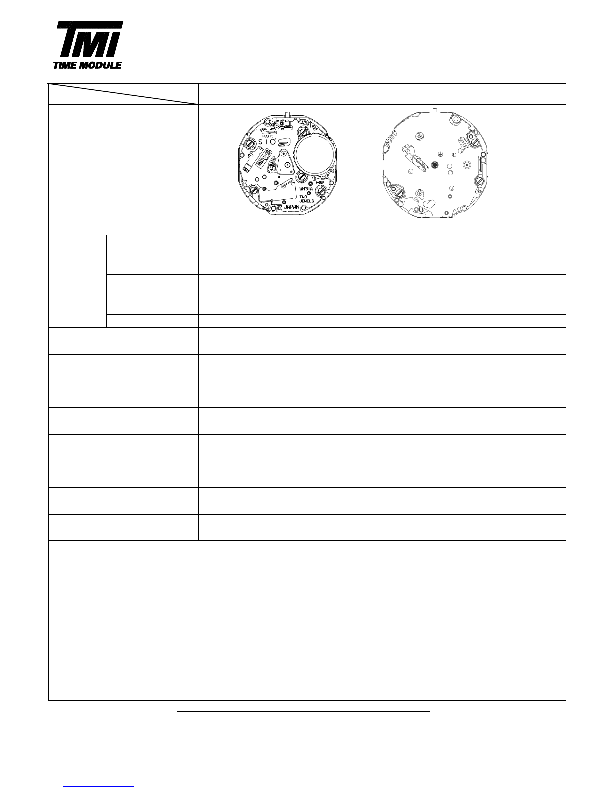
[SPECIFICATION]
φ23.70 mm
22.60 mm : between 12 o'clock and 6 o'clock sides
22.60 mm : between 3 o'clock and 9 o'clock sides
φ23.30 mm
22.10 mm : between 12 o'clock and 6 o'clock sides
21.40 mm : between 3 o'clock and 9 o'clock sides
3.45 mm
Electronic circuit reset switch
Second setting device
SR920SW (Silver oxide battery)
Battery life is approximately 2 years
Use 10-second gate
* Set the winding stem with crown at the normal position
* All specifications are subject to change without notice.
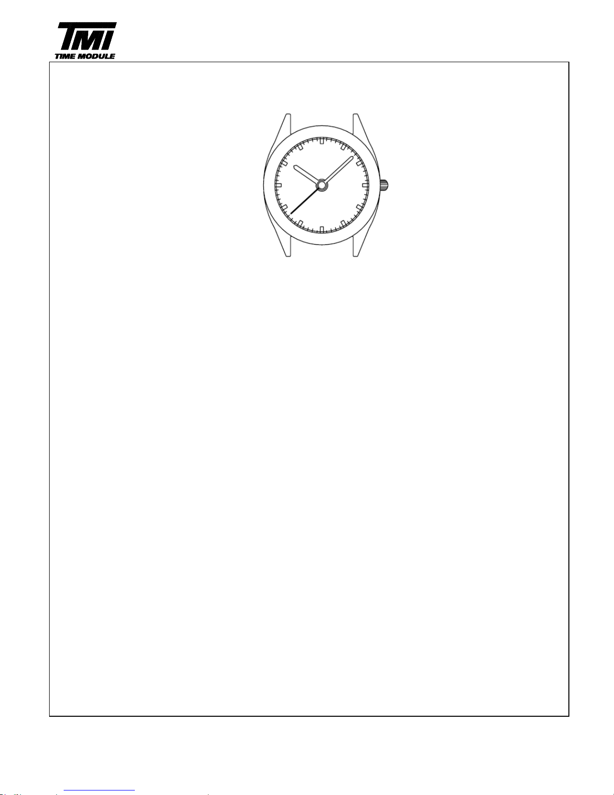
Time indication
3Hands (hour,minute,second)
PARTS CATALOGUE / TECHNICAL GUIDE
Cal.VH31
Version-01
Cal. No.
VH31A
Item
Movement
Movement
size
Outside diameter
Casing diameter
Total height
SII Products
Driving System
Step motor
Additional mechanism
Antimagnetic
≧1600 A/m
Accuracy
Less than ±15seconds : Monthly rate at normal temperature range
Battery
Measuring gate
by quartz tester
Jewels
2 Jewels
1
Page 3
2
SII Products
MOVEMENT VARIATION
Version-01
VH31A
VH31
Page 4

Disassembling procedures Figs.
Reassembling procedures Figs.
①Hour , Minute ,Second hands
②Dial
③0012 354
Support for dial side parts screw
④0604 150
Support for dial side parts
⑤0273 046
Hour wheel
<<VH31A>>
3
SII Products
5
⇒
1
Version-01
VH31A
PARTS CATALOGUE
1
⇒
5
Page 5

Disassembling procedures Figs. Lubricating : Types of oil Oil quantity
Reassembling procedures Figs.
Moebius A
Normal quantity
Moebius F
Liberal quantity
*Battery connection(+)
0351 177
616181914
SII Products
134151721209811127327⇒1
PARTS CATALOGUE
Version-01
VH31A
1⇒27
2 0012 168
Battery connection (+) screw
3 4268 080
Battery connection(+)
4 4216 103
Insulator
7 0144 006
Fourth wheel and pinion
8 0560 005
Friction spring for
fourth wheel and pinion
14 0281 015
Setting wheel
16 0261 052
Minute wheel
and pinion
25 0012 354
Center wheel
bridge screw
27 0221 095
Center wheel and
pinion
23 4002 070
Coil block
5 4270 339
Battery connection(-)
6 0125 321
Train wheel bridge
10 0701 017
Fifth wheel and pinion
15 0391 029
Train wheel
setting lever
17 0383 154
Setting lever
18 0384 452
Yoke
20 0282 452
Clutch wheel
21 0804 169
Intermediate wheel for
date corrector A
19 0351 177
Winding stem
13 4004 474
Circuit block
11 0706 008
Sixth wheel and pinion
9 0231 061
Third wheel and pinion
12 4146 104
Step rotor
26 0121 060
Center wheel bridge
24 4239 065
Stator
22 0012 354
Coil block screw
*1
Main plate
1 Battery
Page 6

・The explanation here is only for the particular point of Cal.VH31A
1.REMARKS ON DISASSEMBLING AND REASSEMBLING
(1)HAND
・How to install hands:
Place the movement directly on a flat metal plate
or such a hard plate when you install the hands.
Necessary procedure to setting hands:
①Set the dial.
②Install the hour and minute and second hands at the 12 o'clock position.
(2)Winding stem
・How to remove:
Pull out the winding stem while pushing
the indented portion of the arrow.
(3)Battery
・How to install:
Insert the battery in the aslant direction as shown by the arrow.
Check the battery connection (+) securely touches the
side face of the battery.
・How to remove:
Firstly slide the battery in the direction of the arrow with tweezers,
and then lift the battery.
(4)Insulator
・How to set:
To insulate between the battery connection (+)
and the battery connection (-), the insulator
should be put at the two pins securely as bellow.
TECHNICAL GUIDE
Version-01
VH31A
SII Products
5
Insulator
Pin
Metal plate
Push
Page 7

・How to set the support of dial side parts:
There are two hooks on the support for dial side parts. (Fig.1)
First , assemble the two hooks on the support for dial side parts
to the position of the built-in height A of the base plate. (Fig.2)
Second , assemble the two hooks on the position of the built-in height B of the base plate. (Fig.3)
example VH31A
Fig.1 Fig.2 (built-in height A) Fig.3 (built-in height B)
TECHNICAL GUIDE
Version-01
VH31A
SII Products
6
height A position
height B position
Page 8

*1: Hour hand
*3:
Second hand
*5:
First click
*2:
Minute hand
*4:
Crown at normal position
・Time setting
1.Pull out the crown to the first click 2.Push the crown back into the normal position
when the second hand is at the in signal.
12 O'clock position.
Turn the crown to set the hour and
minute hands to the time.
SII Products
7
TIME SETTING
OPERATION
Version-01
VH31A
DISPLAY AND CROWN OPERATION
≪VH31A≫
Note:
*4
*1
*3
*2
*5
 Loading...