

Page 1
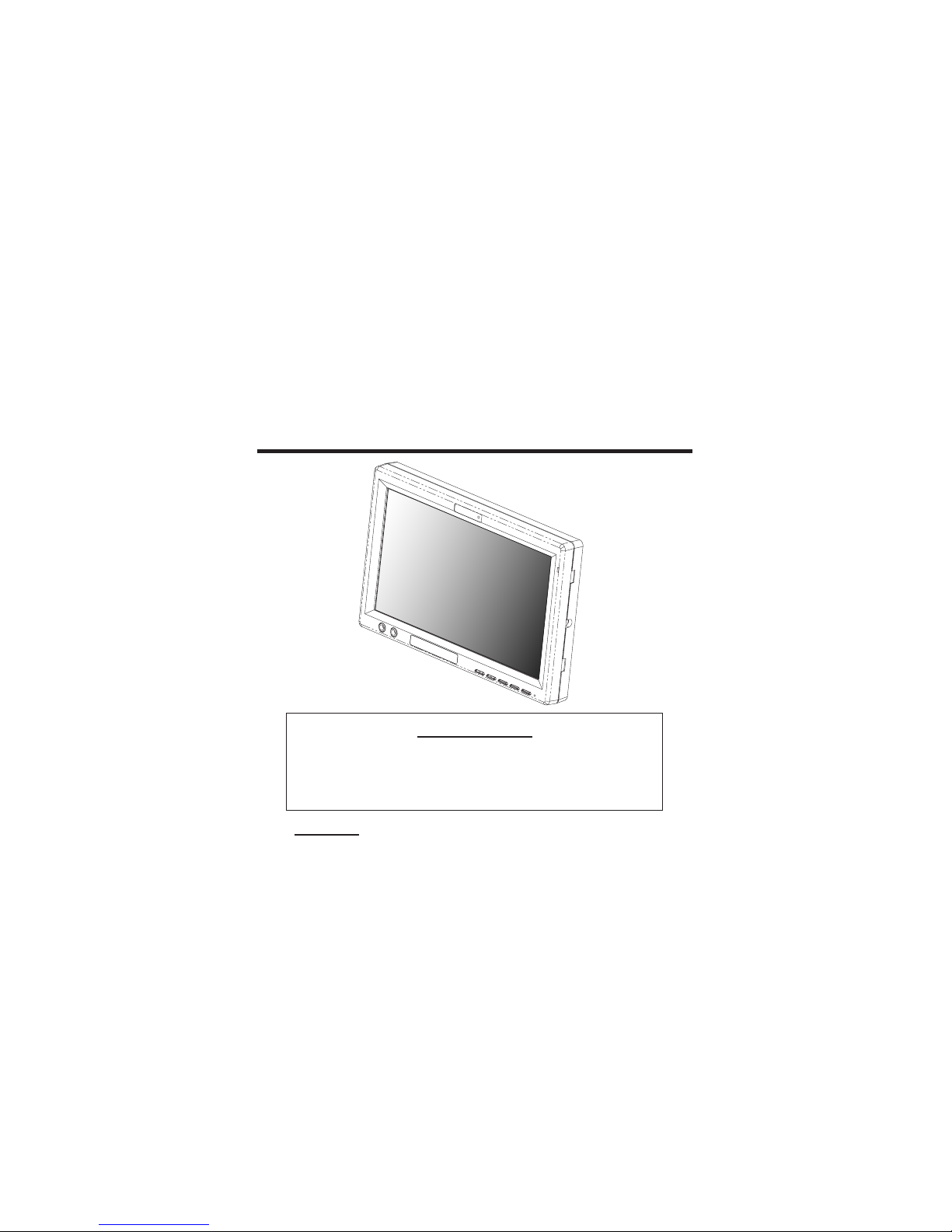
Headrest
7.0" 16:9 Color
Display Monitor
OPERATING
INSTRUCTIONS
Important Notice
It is unlawful in most jurisdictions for a person to drive a motor vehicle which is
equipped with a television or screen that is located in the motor vehicle at
any point forward of the back of the driver's seat, or that is visible directly
or indirectly to the driver while operating the vehicle.
CAUTION
1.
Do not operate the monitor at temperatures below -22°F (-30°C) or above 185°F (85°C).
2.
Keep the monitor clean and dry.3.
4.
Do not drop the monitor or expose to strong impacts.
Do not expose to direct sunlight for extended periods of time.
9100768
TMI PRODUCTS, INC.
Model No.AS700
Page 2
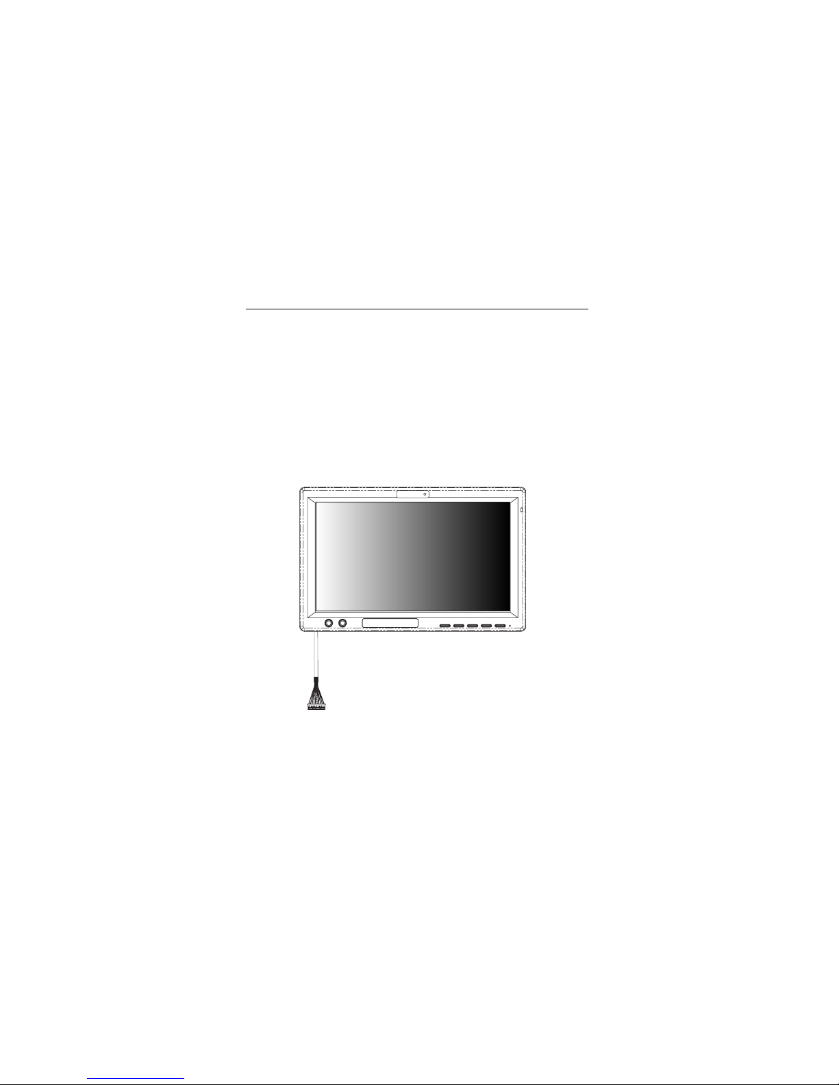
Installation Guide:
The kit includes a protective trim ring and an optional spacer ring for use when the mounting
surface is uneven.
1. Select appropriate locations in your vehicle for the monitor .
2. Be sure there is sufficient depth for the trim ring. Add the spacer ring for shallow locations
with uneven curved surfaces such as upholstery. Be sure there is enough space for both
the trim ring and for any excess interconnect cable.
3. Ensure that the interconnect cable will reach from the monitor location .
4. Create the required opening for the monitor and trim ring. Be sure it is not too large, and
that there is enough space behind the trim ring to store any excess interconnect cable.
Excess cable does not fit within the trim ring.
5. Route the cable through the opening in the trim ring
6. Connect the cable to the monitor.
7. Securely snap the monitor into place.
If you need to remove the monitor from the trim ring, insert a credit card between the monitor and
the trim ring to release the monitor from the flexible locking retainer tabs. Gently pull the monitor
from the trim ring. Very gentle pressure can be applied using the credit card.
01
Cable
Page 3
02
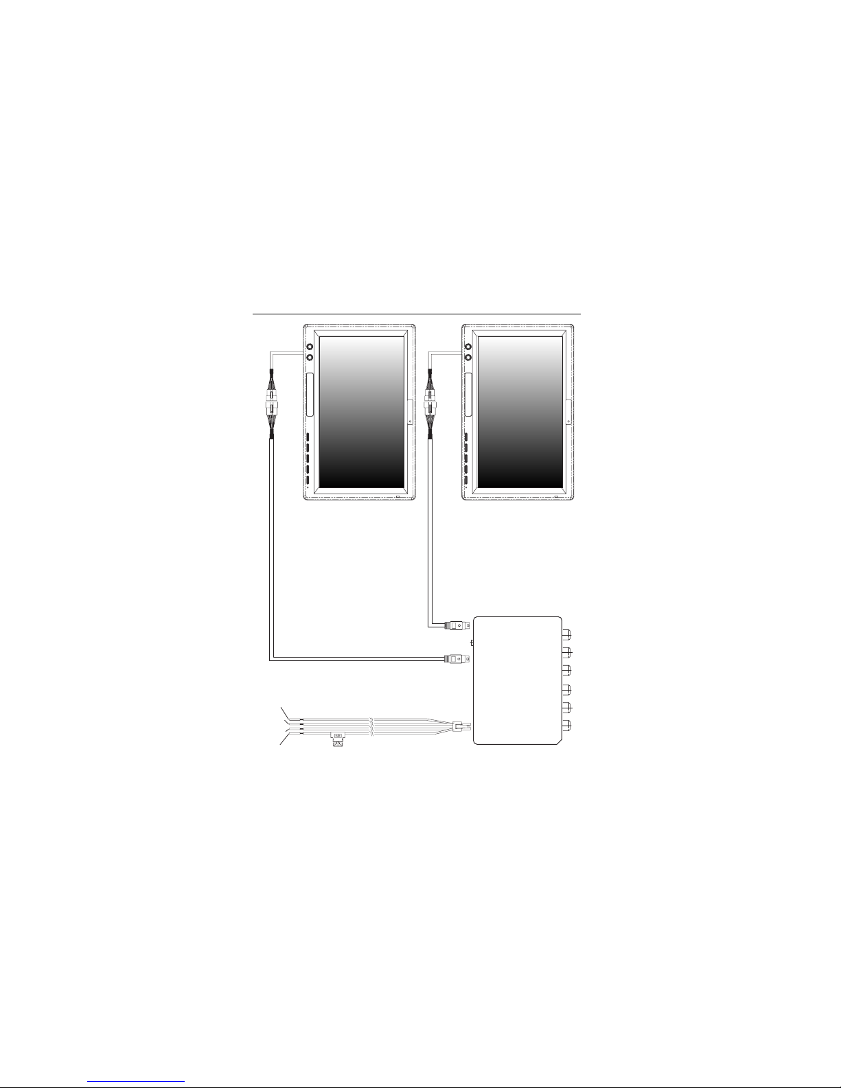
Electrical Connections:
Note:Pleasemakesureallcablesareconnected
correctly, wrong connections will dama ge
the monitor .
POWER CORD
Yellow ---Power
Red --- ACC
Black --- GND
Green --- Park
Passage side
Drive side
AV I N 3
A(L) A(R)V
AV I N 1
A(L) A(R)V
BLACK-GND
RED-ACC
YELLOW-BATTERY
Green-Park
ADAPTORS
INPUT DC-13.2V
FUSE 2A
SERIAL NO.
AD-7071
IR OUTMS
4
4
Page 4
03
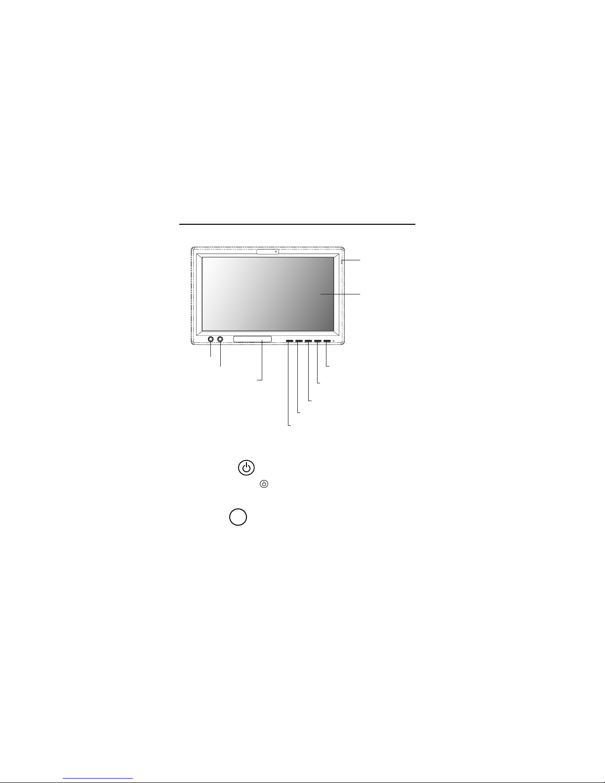
Basic Operation:
Front Control Panel:
10. Earphone
9.A/VAUX
5/!MENU : Activation of Menu Indicator
6/!UP : Positive and Negative Adjustment
3. POWER : ON / OFF / AUX Selection button
(press and hold the button will power off)
4. SOURCE : Select the internal AV1 / AV2 / AV3
player
7/!DOWN : Positive and Negative Adjustment
2. LCD Panel
1. IR Receive
8. IR Transmitter
(2 Input)
2 (POWER)
Pressing this POWER ( ) button will turn the unit on. If unit off, a single
press should turn the unit on.
SOURCESOURCE
3 Source
This button lets you select the internal AV1 / AV2 / AV3 player.
Page 5

04
Basic Operation:
5, 6 Up / Down
Press to move up or down in a menu or to change channel when
watching TV.
MENUMENU
4 Menu
If the source unit selected has a Setup Menu, you can access it by
pressing Source Menu. With the AV1 / AV2 / AV3, this button activates
the screen Constrast / Brightness / Color / Tint / Shapness / Dimmer /
Screen / Reset default feature.
On-Screen-Display Settings:
When monitor is power on, press mode button on remote or power button control panel to select
video inputs AV1/AV2/AV3 NTSC/PAL. (Press and hold power button on control panel
will power off the monitor.)
MODE:
VOLUME:
Press up/down button on remote or on control panel to select "VOLUME" setting, "VOLUME"
setting will show as below (right chart).
VOLUME
Page 6

05
On-Screen-Display Settings:
CONSTRAST:
Press Menu button on remote or on control panel, OSD menu will show on LCD screen as below
(left chart), press up/down button on remote or press and hold up/down button on control panel to
select "CONSTRAST" setting, "CONSTRAST" setting will show as below (right chart).
COLOR:
Press Menu button on remote or on control panel, OSD menu will show on LCD screen as below
(left chart), press up/down button on remote or press and hold up/down button on control panel to
select "COLOR" setting, "COLOR" setting will show as below (right chart).
BRIGHTNESS:
Press Menu button on remote or on control panel, OSD menu will show on LCD screen as below
(left chart) , press enter button on remote or power button on control panel to select "BRIGHTNESS"
setting, "BRIGHTNESS" setting will show as below (right chart).
BRIGHTNESS
CONSTRAST
Page 7

06
On-Screen-Display Settings:
TINT
TINT:
Press Menu button on remote or on control panel, OSD menu will show on LCD
screen as below (left chart), press up/down button on remote or press
and hold up/down button on control panel to select "TINT" setting. "TINT" setting
will show as below (right chart).
SHAPNESS
DIMMER LOW
SHAPNESS:
Press Menu button on remote or on control panel, OSD menu will show on LCD
screen as below (left chart), press up/down button on remote or press
and hold up/down button on control panel to select "SHAPNESS" setting.
"SHAPNESS" setting will show as below (right chart).
DIMMER:
Press Menu button on remote or on control panel, OSD menu will show on LCD
screen as below (left chart), press up/down button on remote or press
and hold up/down button on control panel to select "DIMMER" setting. "DIMMER"
setting will show as below (right chart).
DIMMER HIGH DIMMER MEDIUM
Page 8

07
On-Screen-Display Settings:
FM CHANNEL:
FM CHANNEL
SCREEN:
Press Menu button on remote or on control panel, OSD menu will show on LCD
screen as below (left chart), press up/down button on remote or press
and hold up/down button on control panel to select "SCREEN" setting. "SCREEN"
setting will show as below (right chart).
Press Menu button on remote or on control panel, OSD menu will show on LCD
screen as below (left chart), press up/down button on remote or press
and hold up/down button on control panel to select "FM CHANNEL" setting."SCREEN"
setting will show as below (right chart).
FM MODULE:
Press Menu button on remote or on control panel, OSD menu will show on LCD
screen as below (left chart), press up/down button on remote or press
and hold
up/down button on control panel to select "FM MODULE" setting."FM MODULE"
setting will show as below (right chart).
SCREEN NORMAL
CH1 88.5MHZ
CH2 88.7MHZ
CH3 88.9MHZ
CH4 89.1MHZ
CH5 89.3MHZ
CH6 89.5MHZ
CH7 89.7MHZ
CH8 89.9MHZ
SCREEN ZOOM SCREEN WIDE
FM MODULE
FM MODULE
FM MODULE
ON
OFF
Page 9

08
On-Screen-Display Settings:
BASIC FUNCTIONS :
Press
and hold
Menu button
about 5 seconds
on control panel to select from the
ChannelA/B/OFF
various mode settings, OSD menu will show on LCD screen as
below
(down chart), press up/down button on remote or press
and hold up/down
button on control panel to select "BASIC FUNCTIONS" setting. The mode setting
status will change each time when MENU button is pressed. "MENU"
setting will
show as below (down chart).
IRCHANNEL CH A
AVSYSTEM AV1 /2 /3
MIRROR OFF
SCREEN OFF
DIMMER MANUAL
FM-FUNC ON
EXIT
MENU
IRCHANNEL CH B
AVSYSTEM AV1 /2
MIRROR OFF
SCREEN OFF
DIMMER MANUAL
FM-FUNC ON
EXIT
MENU
SOFTWAREVERSION 7071V1.0 SOFTWAREVERSION 7071V1.0
IRCHANNEL CH A
AVSYSTEM AV1 /2 /3
MIRROR OFF
SCREEN OFF
DIMMER MANUAL
FM-FUNC ON
EXIT
MENU
IRCHANNEL CH B
AVSYSTEM AV1 /2 /3
MIRROR ON
SCREEN OFF
DIMMER MANUAL
FM-FUNC ON
EXIT
MENU
SOFTWAREVERSION 7071V1.0 SOFTWAREVERSION 7071V1.0
IRCHANNEL CH A
AVSYSTEM AV1 /2 /3
MIRROR OFF
SCREEN OFF
DIMMER MANUAL
FM-FUNC ON
EXIT
MENU
IRCHANNEL CH B
AVSYSTEM AV1 /2 /3
MIRROR OFF
SCREEN OFF
DIMMER MANUAL
FM-FUNC ON
EXIT
MENU
IRCHANNEL CH OFF
AVSYSTEM AV1 /2 /3
MIRROR OFF
SCREEN OFF
DIMMER MANUAL
FM-FUNC ON
EXIT
MENU
SOFTWAREVERSION 7071V1.0 SOFTWAREVERSION 7071V1.0 SOFTWAREVERSION 7071 V1.0
RESET DEFAULT
RESET DEFAULT
Press Menu button on control panel, OSD menu will show on LCD screen as below (left chart),
Press up/down button on control panel to select "RESET DEFAULT" setting. "RESET" setting will
show as below (right chart).
Page 10

09
The Wide Screen Universal Monitor includes mounting options described in the
following sections. Before you install the monitor, consider the following
important notices:
NEVER install this monitor where it can be viewed from the driving position;
1.
2.
3.
this is a violation of many state and local vehicle codes.
Avoid mounting locations where there is a risk of impact with a passenger in
the event of an accident.
Always mount the monitor securely using the mounting hardware that is
provided. Do not use the monitor unless it is properly secured to the vehicle.
Installation Notes:
IRCHANNEL CH A
AVSYSTEM AV1/2/3
MIRROR OFF
SCREEN OFF
DIMMER MANUAL
FM-FUNC ON
EXIT
MENU
IRCHANNEL CH B
AVSYSTEM AV1 /2 /3
MIRROR OFF
SCREEN OFF
DIMMER MANUAL
FM-FUNC OFF
EXIT
MENU
SOFTWAREVERSION 7071V1.0 SOFTWAREVERSION 7071V1.0
IRCHANNEL CH A
AVSYSTEM AV1/2/3
MIRROR OFF
SCREEN OFF
DIMMER MANUAL
FM-FUNC ON
EXIT
MENU
IRCHANNEL CH B
AVSYSTEM AV1 /2 /3
MIRROR OFF
SCREEN OFF
DIMMER MANUAL
FM-FUNC OFF
EXIT
MENU
SOFTWAREVERSION 7071V1.0 SOFTWAREVERSION 7071V1.0
IRCHANNEL CH A
AVSYSTEM AV1/2/3
MIRROR OFF
SCREEN OFF
DIMMER MANUAL
FM-FUNC ON
EXIT
MENU
IRCHANNEL CH B
AVSYSTEM AV1 /2 /3
MIRROR OFF
SCREEN AUTO
DIMMER MANUAL
FM-FUNC ON
EXIT
MENU
IRCHANNEL CH OFF
AVSYSTEM AV1/2/3
MIRROR OFF
SCREEN ON
DIMMER MANUAL
FM-FUNC ON
EXIT
MENU
SOFTWAREVERSION 7071V1.0 SOFTWAREVERSION 7071V1.0 SOFTWAREVERSION 7071V1.0
Basic Functions :
Page 11

Highlights:
7" Active TFT LCD
AS700 with built-in FMM
AS700
- Without FMM
- Can be use for visor monitor
Monitor can be turned ON when Parking is high or floating
Monitor will shut down when parking is set to Low.
Front access AUX and Headphone jacks
No AV Box
Very competitive cost
HS3.1 replacement
A/V Input and Output:
Input:
Input from DVD loader (RCA)
Input from Game Console or the second DVD player (RCA)
Front bezel Aux input
Output:
Diver side FMM for Audio
Driver and Passenger side IR audio
Front bezel earphone
10
This equipment has been tested and found to comply with the limits for a Class B digital device, pursuant to part 15 of the FCC
rules. These limits are designed to provide reasonable protection against harmful interference in a residential installation. This
equipment generates, uses and can radiate radio frequency energy and, if not installed and used in accordance with the
instructions, may cause harmful interference to radio communications. However, there is no guarantee that interference will not
occur in a particular installation. If this equipment does cause harmful interference to radio or television reception, which can be
determined by turning the equipment off and on, the user is encouraged to try to correct the interference by one or more of the
following measures:
-Reorient or relocate the receiving antenna.
-Increase the separation between the equipment and receiver.
-Connect the equipment into an outlet on a circuit different from that to which the receiver is connected.
-Consult the dealer or an experienced radio/TV technician for help.
You are cautioned that changes or modifications not expressly approved by the party responsible for compliance could void your
authority to operate the equipment.
This device complies with Part 15 of the FCC Rules. Operation is subject to the following two conditions: (1) this device may
not cause harmful interference and (2) this device must accept any interference received, including interference that may cause
undesired operation
FCC RF Radiation Exposure Statement:
1. This Transmitter must not be co-located or operating in conjunction with any other antenna or transmitter.
2. This equipment complies with FCC RF radiation exposure limits set forth for an uncontrolled environment. This equipment
should be installed and operated with a minimum distance of 20 centimeters between the radiator and your body.
 Loading...