

TM Induction Heating SURETHERM 20X, SURETHERM 10X, SURETHERM 30X User Manual
ISO 9001:2008
ID 9108623968
www.tuv.com
User Manual
Note
Check delivery for possible damage caused by transport without
delay. Should damage be detected, please inform carriers
immediately.
As our products are subject to continuous improvement, we reserve
the right to make changes.
tminductionheating.com
info@tminductionheating.com
+31 (0) 341 434454
+31 (0) 341 434464
WEB
MAIL
TEL
FAX
ADDRESS TM Induction Heating
Nobelstraat 14
3846 CG Harderwijk
The Netherlands
T & M Techniek BV
BTW NL800643136B01
KvK 08054481
ISO 9001:2008
ID 9108623968
www.tuv.com

INDUCTION HEATING 5
Operating conditions 5
SAFETY GUIDELINES 6
Safety precautions 7
Safety instructions 8
Safety features 9
INSTALLATION 10
Scope of delivery 10
Unboxing 10
Installation process 11
SETTING UP THE WORKPIECE 12
Choosing the yoke 13
Positioning the magnetic temperature probe(s) 14
OPERATION 15
Temperature Mode, using one sensor 16
Ramp Mode 17
Temperature Mode, using two sensors 18
Time Mode 19
User menu 20
MAINTENANCE 21
MALFUNCTION 22
Adjusting the yoke 22
Errors 23
SPECIFICATIONS 24
Dimensions 25
Workpiece dimensions 26
Technical data 27
Extra information 28
Electrical drawing 29
STATEMENT OF CONFORMITY 31
1
2
3
4
5
6
7
8
9
CONTENTS

TM INDUCTION HEATING
4
ST 2.0 |
TM INDUCTION HEATING
5
ST 2.0 |
1
induction heaters are used to heat rolling bearings. Other
metal components forming a closed circuit such as bushings, shrink rings,
pulleys and gears can also be heated. This will facilitate mounting where
an interference t is required.
Our range of standard heaters are designed to heat the workpiece to a
maximum temperature of 240ºC (464°F). The heaters can be used on a
continuous basis. Always place the temperature sensor on the workpiece
to check the heating cycle. When heating an object using Time Mode, the
heating cycle must be checked using an external temperature meter.
CAUTION
Bearings generally should only be heated to a maximum temperature of
120ºC (248ºF). Do not use induction heaters for bearings or workpieces
with dimensions outside the ranges specied in this manual. Do not
switch off the heater with the main switch while heating cycle is running.
The heater is designed to be used in an industrial environment with an
ambient temperature of 0°C to 40°C (32°F to 104°F) and an atmospheric
humidity between 5% and 90%, non-condensing. The induction heater is
intended for indoor use only.
INDUCTION HEATING
OPERATING
CONDITIONS

TM INDUCTION HEATING
6
ST 2.0 |
SAFETY GUIDELINES
2
The operating instructions should always be followed when using an
induction heater.
TM Induction Heating shall not be held liable for damages caused by
improper handling or by use which does not comply with the designated
purpose. Prerequisites for the operator: He/she must be authorised for
use of the heater and must be familiar with the safety precautions.
In order to prevent danger or damage to the induction heater or workpiece,
follow these guidelines:
` All repairs must be carried out by an ofcial TM Induction Heating
distributor.
` Use original spare parts only.
` Protect the heater from water or very high humidity.
` Protect the heater core and yokes against corrosion, damage and
deformation.
` Only preheat bearings to max. 120°C (248°F).
` To ensure proper operation of the device, it is important to provide
the device with the latest software updates. A description can be
found in chapter 5 - OPERATION, page 20 - USER MENU.
TM INDUCTION HEATING
7
ST 2.0 |
SAFETY
PRECAUTIONS
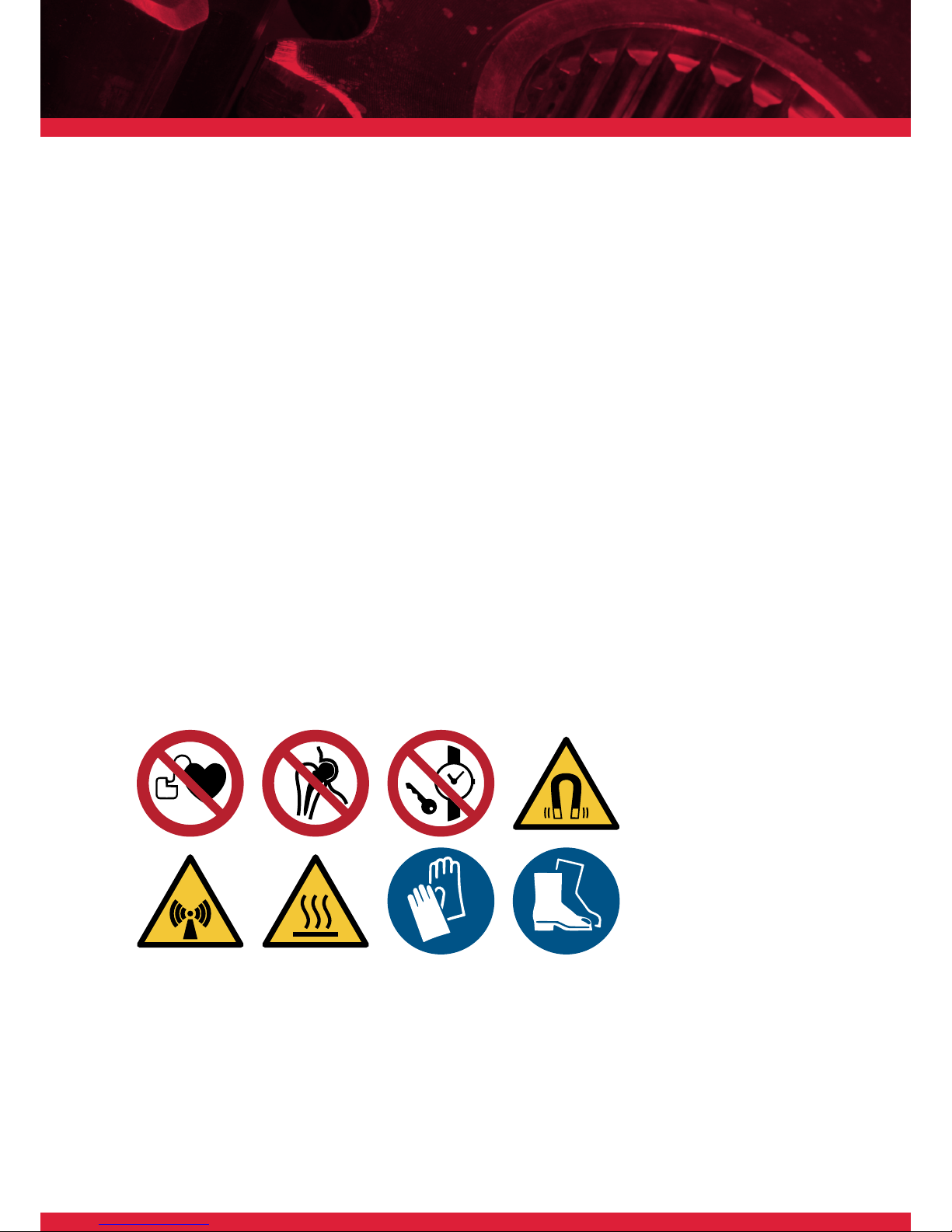
` Since a magnetic eld
4&5
is generated by the induction heater, people
wearing a pacemaker 1 or other implant device 2 should not work or
be in the immediate vicinity of the device. Other sensitive equipment
such as wrist watches, magnetic carriers, electronic circuits, etc. 3
might also be affected. The safety distance is 0.5 meters (19”).
` Use protective gloves as protection against burns to hands. The gloves
delivered are suitable for use up to temperatures of 150°C (302°F).
` Hot surface, avoid contact
6
.
` Do not operate an induction heater in areas where there is risk of
explosion.
` Wear safety shoes
8
.
1.
2. 3. 4.
8.7.
6.5.

TM INDUCTION HEATING
8
ST 2.0 |
` The user should have an appreciation of the contents of this user
manual, and be familiar with safe workshop practices.
` Follow the user manual at all times.
` Ensure that the induction heater operates at the correct supply
voltage. If the heater is not supplied with a plug, changes should only
be made by a suitably qualied electrician.
` Do not use or store the heater in humid environments. The heater is
designed for indoor use only.
` Use proper handling equipment, appropriate for the weight of the
workpiece and/or yoke. Never support components with a metal cable
or have any hanging in the proximity of the magnetic eld. Extremely
high currents can ow through the cable causing it to heat up quickly,
resulting in a risk of burning.
` Do not place any metal objects near the yokes and poles.
` Place heater on a stable, horizontal surface.
` Keep a minimum distance of 1 metre (38”) to surrounding objects.
` Use only in well ventilated areas.
` Do not heat objects containing oil, grease or similar substances.
Prevent possible generation of fumes and smoke.
` Do not inhale fumes or smoke from heated parts.
` Do not move or lift heater when warm after heating cycle.
` Do not touch the heater core during heating cycle.
SAFETY
INSTRUCTIONS
TM INDUCTION HEATING
9
ST 2.0 |
Should an error occur during the heating process, the induction heater will
automatically stop. The corresponding error will be displayed on screen.
In the case of user error, the display indicates what steps are to be taken
to correct the problem. More information about the types of errors can
be found in chapter 7 - ERRORS.
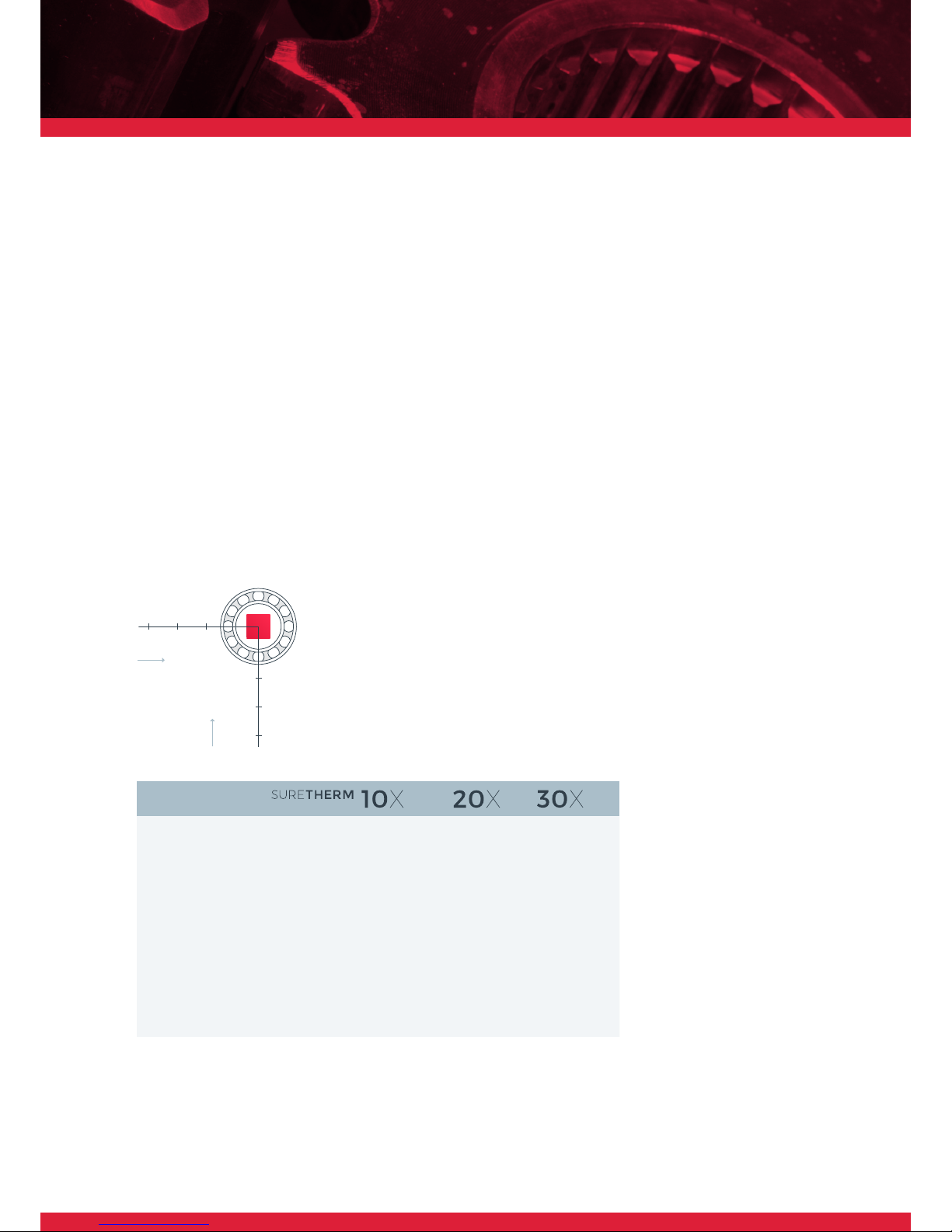
An induction heater produces an electromagnetic eld within a coil to
transfer energy to a workpiece. The table below shows values of the ux
density in microTesla (µT). These measurements can be used as a guide
conforming to local regulations regarding
the maximum time exposure to magnetic
elds. Different congurations may give
different values. It is impossible to provide
values for all combinations as the variety
of bearing types in combination with the
different yokes is large.
Total 50Hz RMS eld for magnetic measurement results. Max. magnetic
ux in safe exposure area, according to the German BG 11 Regulations
is 423
µ T.
SAFETY
FEATURES
MP1x 81 249 283
MP2x 16 34 74
MP3x 1 11 28
MP1y 156 181 185
MP2y 27 24 78
MP3y 9 9 41
Measurement position (cm) B-eld
total
(µT)
MP2x60MP1x
30
MP3x
90
30
60
90
MP1y
MP2y
MP3y
X
(cm)
Y
(cm)
TM INDUCTION HEATING
10
ST 2.0 |
INSTALLATION
3
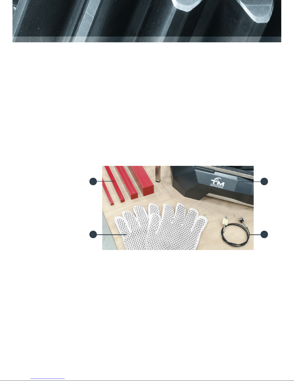
SCOPE OF
DELIVERY
Contents of the box
1. / /
2. Yoke(s)
3. Temperature probe(s)
4. Heat-resistant gloves
5. User Manual
6. Quickstart guide
1
4 3
2
Note
The comes with yokes 14, 25, and 40 included. The
yokes for and are all optional. The
heat-resistant gloves may differ from the picture above.
Follow the instructions specic for this heater on the supplied Quickstart
guide. If the Quickstart guide is not included in this box, please contact
your distributor or TM Induction Heating directly. The induction heater
must always be transported in the original box, thus also on return to the
manufacturer/distributor.
UNBOXING
TM INDUCTION HEATING
11
ST 2.0 |
Insert the plug into a shockproof wall socket
and then connect the heater to mains
electricity.
Turn main switch from 0 to 1. The heater
will emit a short beep and the touchscreen
displays the main menu. The induction heater
is now ready for use.
INSTALLATION
PROCESS
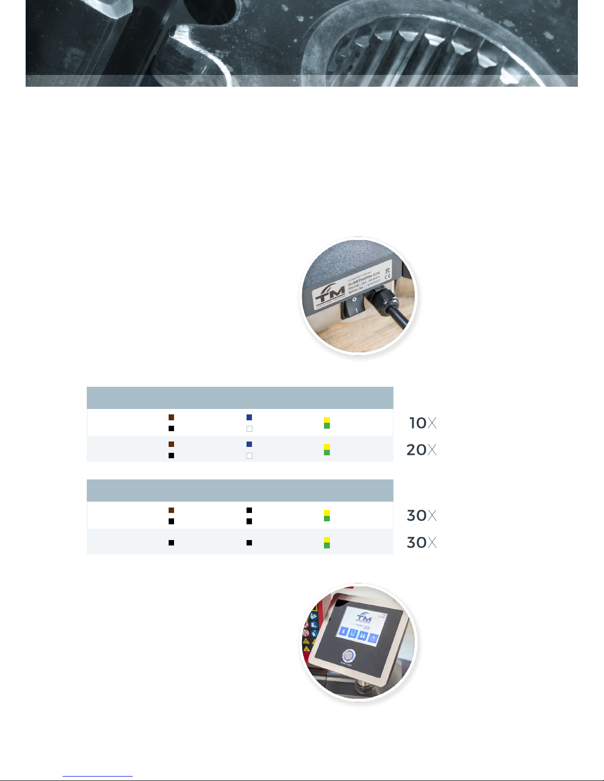
Ensure that supply voltage and current meet the specications. These can
be found on the type plate at the back of the
induction heater.
Each induction heater is provided with a plug,
but there are a large number of plug types.
Should the plug not t your power supply, a
suitable plug must be afxed by a qualied
electrician. Voltages may differ for customized
heaters.
Phase Neutral Ground
Voltage
110-230V
Green/Yellow
Blue
White
(USA)
Brown
Black
(USA)
110-230V
Green/Yellow
Blue
White
(USA)
Brown
Black
(USA)
Phase X / L1 Phase Y / L2 Ground
Voltage
460-575V
Green/Yellow
Black Black
400-440V
Green/Yellow
Brown
Black
Black
Black
 Loading...