


NanoCam3D Mk.1 Instruction Manual
IMPORTANT – READ CAREFULLY BEFORE USE
KEEP FOR FUTURE REFERENCE
Contents
1 Introduction and Designated Use................................................................................................. 3
1.1 Safety Instructions................................................................................................................4
1.2 Quick Start Guide.................................................................................................................. 4
2 Optional Camera Setup................................................................................................................ 4
2.1 Control Elements..................................................................................................................5
2.2 Video Norm Setup................................................................................................................. 5
2.3 3D Video Mode Setup........................................................................................................... 5
2.4 Reset to Factory Default Settings.........................................................................................6
2.5 Sensor Vertical Adjustment...................................................................................................6
2.6 Side-by-Side Offset Adjustment............................................................................................ 7
2.7 Auto Exposure Adjustments..................................................................................................8
3 Warranty....................................................................................................................................... 9
4 Disposal and Environmental Protection........................................................................................9
5 Manufacturer Information and Technical Support.........................................................................9
6 Regulatory Notes........................................................................................................................ 10
6.1 United States of America....................................................................................................10
6.2 Canada............................................................................................................................... 10
6.3 European Union.................................................................................................................. 11
List of Figures
Figure 1: Camera front and rear side................................................................................................3
Figure 2: Control Elements............................................................................................................... 5
Figure 3: Vertically misaligned images (left) and correctly aligned images (right).............................6
Figure 4: Side-by-Side offset positions: to the left, center, to the right..............................................7
List of Abbreviations
AE Auto Exposure
ESD Electrostatic Discharge
FS Field-Sequential
CVBS Color Video Blanking Signal
FPV First Person View
SBS Side-by-Side
SELV Separated/Safety Extra Low Voltage
Page 1 of 12
Subject to change without notice.
EN

NanoCam3D Mk.1 Instruction Manual
IMPORTANT – READ CAREFULLY BEFORE USE
KEEP FOR FUTURE REFERENCE
TMG - Ingenieurbüro UG (haftungsbeschränkt), the “Manufacturer”, is disclosing this Document
and Intellectual Property (hereinafter “the Product”) to you for the intended use as a FPV camera
for radio controlled model aircraft. The Manufacturer expressly disclaims any liability arising out of
the application or use of the Product. The Manufacturer reserves the right to make changes, at any
time, to the Product as deemed desirable in the sole discretion of the Manufacturer. The
Manufacturer assumes no obligation to correct any errors contained herein or to advise you of any
correction if such be made. The Manufacturer will not assume any liability for the accuracy or
correctness of any engineering or technical support or assistance provided to you in connection
with the Product.
THE PRODUCT IS PROVIDED “AS IS” WITH ALL FAULTS, AND THE ENTIRE RISK AS TO ITS
FUNCTION AND IMPLEMENTATION IS WITH YOU. YOU ACKNOWLEDGE AND AGREE THAT
YOU HAVE NOT RELIED ON ANY ORAL OR WRITTEN INFORMATION OR ADVICE, WHETHER
GIVEN BY THE MANUFACTURER, OR ITS AGENTS OR EMPLOYEES. THE MANUFACTURER
MAKES NO OTHER WARRANTIES, WHETHER EXPRESS, IMPLIED, OR STATUTORY,
REGARDING THE PRODUCT, INCLUDING ANY WARRANTIES OF MERCHANTABILITY,
FITNESS FOR A PARTICULAR PURPOSE, TITLE, AND NON-INFRINGEMENT OF THIRDPARTY RIGHTS. IN NO EVENT WILL THE MANUFACTURER BE LIABLE FOR ANY
CONSEQUENTIAL, INDIRECT, EXEMPLARY, SPECIAL, OR INCIDENTAL DAMAGES,
INCLUDING ANY LOST DATA AND LOST PROFITS, ARISING FROM OR RELATING TO YOUR
USE OF THE PRODUCT, EVEN IF YOU HAVE BEEN ADVISED OF THE POSSIBILITY OF SUCH
DAMAGES. THE TOTAL CUMULATIVE LIABILITY OF THE MANUFACTURER IN CONNECTION
WITH YOUR USE OF THE PRODUCT, WHETHER IN CONTRACT OR TORT OR OTHERWISE,
WILL IN NO EVENT EXCEED THE AMOUNT OF FEES PAID BY YOU TO THE MANUFACTURER
HEREUNDER FOR USE OF THE PRODUCT. YOU ACKNOWLEDGE THAT THE FEES, IF ANY,
REFLECT THE ALLOCATION OF RISK SET FORTH IN THIS AGREEMENT AND THAT THE
MANUFACTURER WOULD NOT MAKE AVAILABLE THE PRODUCT TO YOU WITHOUT THESE
LIMITATIONS OF LIABILITY.
Notice: Some jurisdictions do not allow the exclusion or limitation of liability as outlined above, so
the above limitation or exclusion may not apply to you.
The Product is not designed or intended for use in the development of on-line control equipment in
hazardous environments requiring fail-safe controls, such as in the operation of nuclear facilities,
aircraft navigation or communications systems, air traffic control, life support, or weapons systems
(“High-Risk Applications”). The Manufacturer specifically disclaims any express or implied
warranties of fitness for such High-Risk Applications. You represent that use of the Product in such
High-Risk Applications is fully at your risk.
© 2017 TMG - Ingenieurbüro UG (haftungsbeschränkt). All rights reserved.
cinemizer is a registered trademark of Carl Zeiss. Molex and PicoBlade are registered trademarks
of Molex, LLC. All other trademarks listed herein are the property of their respective owners.
NanoCam3DMk1 Manual EN V1.0
Page 2 of 12
Subject to change without notice.
EN
NanoCam3D Mk.1 Instruction Manual
IMPORTANT – READ CAREFULLY BEFORE USE
KEEP FOR FUTURE REFERENCE
1 Introduction and Designated Use
NanoCam3D Mk.1 is a stereoscopic FPV camera for radio-controlled vehicles, in particular for
micro quad-copters. The camera is delivered in a pre-calibrated and ready-to-use state. The
factory settings of the camera are:
Video norm: PAL,
3D-Mode: Squeezed Side-by-Side 3D,
Image swap: No swap,
Auto exposure algorithm: Average Brightness Tracking.
These settings provide compatibility with most of the currently available 3D-capable FPV goggles
like FatShark Dominator HD V1-V3 and Dominator V3; Zeiss Cinemizer, Cinemizer Plus and
Cinemizer OLED as well as AOMWAY Commander V1. Users of FatShark Attitude V3 or Headplay
PCS video goggles (with Field-Sequential 3D support) should refer to chapter 2.3 for video setup.
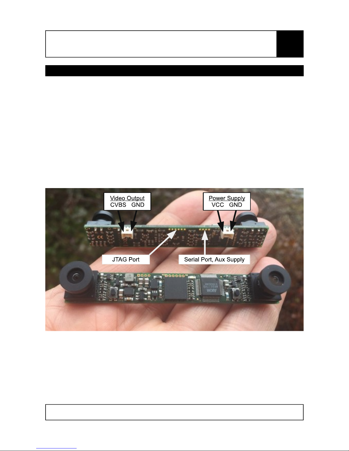
The following picture shows all camera connectors and data ports.
Figure 1: Camera front and rear side
The JTAG port is used for device programming and typically not of interest for operational use. The
serial port with auxiliary 3.3V supply connects the camera to future devices, e.g. for generation of a
stereoscopic on-screen display (3D-OSD).
Page 3 of 12
Subject to change without notice.
EN
NanoCam3D Mk.1 Instruction Manual
IMPORTANT – READ CAREFULLY BEFORE USE
KEEP FOR FUTURE REFERENCE
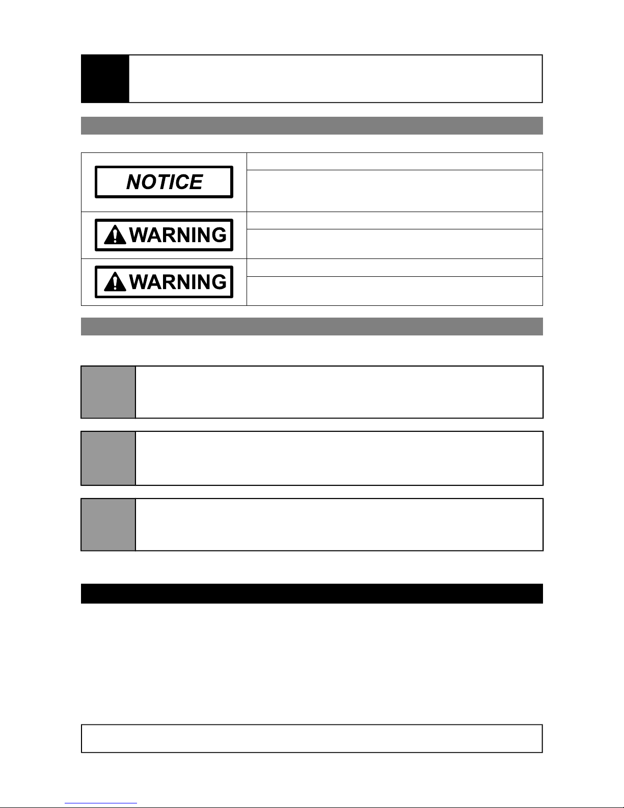
1.1 Safety Instructions
Risk of electrostatic discharge!
Take appropriate measures to protect the camera against
electrostatic discharge during assembly, technical modification
and operation.
Risk of electric shock!
Operate camera with Separated/Safety Extra Low Voltage
(SELV) power sources only!
Risk of fire! Burn hazard!
Operate the camera only with DC voltage between +3V and
+16V!
1.2 Quick Start Guide
For a quick setup with factory defaults follow the subsequent instructions.
1
Connect the camera's video output with suitable Molex PicoBlade™ connectors to
your video transmitter. Notice the CVBS/GND pin assignment. If possible, use a
dedicated ground wire between camera and video transmitter.
2
Connect the camera’s power supply port to a DC power supply (min. +3V, max.
+16V) using a suitable Molex PicoBlade™ connector. Notice the VCC/GND pin
assignment. Both GND pins on camera’s video output and camera’s power supply
are directly connected and hence of the same electric potential.
3
Power-up the camera and check whether the green status LED is continuously on.
Check the received video signal with your FPV goggle or a test monitor. FPV
goggles may need to be put into 3D mode manually. See the manual of your FPV
goggle if unsure how to put the goggle into 3D-mode.
Enjoy your first flights with NanoCam3D Mk.1 and become familiar with FPV in 3D.
2 Optional Camera Setup
The camera has only two control elements on the front side: push buttons 1 and 2. These push
buttons are used for camera set-up and adjustment purposes. The camera’s status LED indicates
the current state of operation.
The camera features a number of setup and adjustment modes to improve user experience. All
adjustments are executed using the two push buttons on the front side of the camera. The result of
these adjustments is applied and saved for future use into a nonvolatile memory section of the
camera's video processing unit.
Page 4 of 12
Subject to change without notice.
EN

NanoCam3D Mk.1 Instruction Manual
IMPORTANT – READ CAREFULLY BEFORE USE
KEEP FOR FUTURE REFERENCE
2.1 Control Elements
Figure 2: Control Elements
Status LED
State Remark
Off No power supply. Camera out of operation.
On Normal operation.
Blinking Camera in setup or adjustment mode.
2.2 Video Norm Setup
The camera’s video norm can be selected between PAL (factory default) or NTSC. It can be
changed by executing the following procedure. The video norm setup procedure can be canceled
at any time by power-cycling the camera.
Power off camera.
Press push button 1 and keep it pressed.
Power on camera and release push button 1. The camera’s status LED starts to flash.
Flashing cycle indicates current video norm setting (PAL = repeated single flash, NTSC =
repeated double flash).
Press and release push button 2 to toggle between PAL and NTSC. LED flash cycle
changes accordingly.
Press and release push button 1 to save setting and restart camera with new setting.
2.3 3D Video Mode Setup
The camera’s 3D-mode can be selected between squeezed side-by-side 3D (factory default) and
field-sequential 3D, both with normal (factory default) and swapped images. The 3D-mode can be
changed by executing the following procedure, which can be canceled at any time by powercycling the camera.
Power off camera.
Press push button 2 and keep it pressed.
Page 5 of 12
Subject to change without notice.
EN

NanoCam3D Mk.1 Instruction Manual
IMPORTANT – READ CAREFULLY BEFORE USE
KEEP FOR FUTURE REFERENCE
Power on camera and release push button 2. The camera’s status LED starts to flash.
Flashing cycle indicates current 3D-mode and image swap setting (SBS no swap =
repeated single flash, SBS swapped = repeated double flash, FS no swap = repeated triple
flash, FS swapped = repeated quadruple flash).
Press and release push button 1 to toggle between these 4 possible modes. LED flash
cycle changes accordingly.
Press and release push button 2 to save setting and restart camera with new setting.
2.4 Reset to Factory Default Settings
It is possible to reset the camera to default settings by executing the following procedure. Notice
that also the camera’s adjustment settings (see following chapters) will be erased.
Power off camera.
Press both push buttons 1 and 2 and keep them pressed.
Power on camera, LED flashes fast.
Release both push buttons to execute camera reset and to restart camera with factory
defaults.
2.5 Sensor Vertical Adjustment
Manufacturing tolerances sometimes lead to vertically misaligned left and right images. This effect
is most prominent in side-by-side 3D mode (Figure 3).
The camera is able to compensate such misalignment without loss of resolution or black bar
padding as the utilized image sensors provide extra video pixels for that purpose. Follow the
procedure outlined below for vertical sensor adjustment. The procedure can be canceled at any
time by power-cycling the camera.
Power on camera and display video signal on a suitable test monitor or video goggle. The
adjustment should be made in side-by-side 3D mode.
Press push button 1 and keep it pressed for ca. 1 sec until the status LED flashes fast, then
release push button 1.
Page 6 of 12
Subject to change without notice.
EN
Figure 3: Vertically misaligned images (left) and correctly aligned images (right)

NanoCam3D Mk.1 Instruction Manual
IMPORTANT – READ CAREFULLY BEFORE USE
KEEP FOR FUTURE REFERENCE
The camera is now in online calibration mode, which is indicated by a slow LED flashing
cycle. There are two different adjustment modes (Sensor Vertical Adjustment Mode =
repeated single flash, Side-by-Side Offset Adjustment Mode = repeated double flash), here
the required Sensor Vertical Adjustment Mode is automatically preselected.
Activate Sensor Vertical Adjustment Mode by pressing push button 1 again and keep it
pressed for ca. 1 sec until the status LED flashes fast. Then release push button 1.
Horizontal lines are displayed over the SBS-video signal to assist the following video image
alignment.
Now press and release one of the two push buttons at a time to vertically align left and right
video image. Each push button is responsible for one of the two possible shift directions
(left down/right up; left up/right down). Input is accepted upon release of the respective
push button. The possible range for vertical image alignment is +/- 36 video lines.
When done press push button 1 again and keep it pressed for ca. 1 sec until the status
LED indicates a solid signal, then release push button 1. This will terminate the Sensor
Vertical Adjustment Mode. The vertical adjustment settings will be saved and the camera
restarts with the new settings.
2.6 Side-by-Side Offset Adjustment
This adjustment mode is meant as a means to compensate optical imperfections of FPV video
goggles that do not separate the left and right picture of squeezed side-by-side input video
correctly in the middle of the video frame. A typical symptom is the visibility of portions of the right
hand side image in the left display of the goggle or vice versa (Figure 4).
This effect can be mitigated with the camera by slightly shifting the whole side-by-side raw video
arrangement to the left or to the right, without compromising the raw side-by-side video. Follow the
procedure outlined below for side-by-side offset adjustment. The procedure can be canceled at any
time by power-cycling the camera.
Power on camera and display video signal on a suitable test monitor or video goggle. This
adjustment is only applicable for side-by-side 3D mode.
Press push button 1 and keep it pressed for ca. 1 sec until the status LED flashes fast, then
release push button 1.
Page 7 of 12
Subject to change without notice.
Figure 4: Side-by-Side offset positions: to the left, center, to the right
EN

NanoCam3D Mk.1 Instruction Manual
IMPORTANT – READ CAREFULLY BEFORE USE
KEEP FOR FUTURE REFERENCE
The camera now is in online calibration mode, which is indicated by a slow LED flashing
cycle. Currently there are two different adjustment modes (Sensor Vertical Adjustment
Mode (default) = repeated single flash, Side-by-Side Offset Adjustment Mode = repeated
double flash). The required Side-by-Side Offset Adjustment Mode needs to be selected
manually in the next step.
Select Side-by-Side Offset Adjustment Mode by pressing and releasing either push button 1
or push button 2. The selected adjustment mode is indicated by the corresponding flashing
sequence of the LED. For Side-by-Side Offset Adjustment Mode the LED must show a
repeated double-flash cycle.
Activate Side-by-Side Offset Adjustment Mode by pressing push button 1 again and keep it
pressed for ca. 1 sec until the status LED flashes fast. Then release push button 1.
Now press and release one of the two push buttons at a time to horizontally shift the whole
side-by-side video image. Each push button is responsible for one of the two possible shift
directions (to the left, to the right). Input is accepted upon release of the respective push
button. The possible shift range for image alignment is +/- 4 shift steps.
When done press push button 1 again and keep it pressed for ca. 1 sec until the status
LED indicates a solid signal, then release push button 1. This will terminate the Side-bySide Offset Adjustment Mode. The side-by-side offset adjustment settings will be saved and
the camera restarts with the new settings.
2.7 Auto Exposure Adjustments
The auto exposure (AE) algorithms running on both image sensors perform automatic adjustments
of the image brightness by controlling the exposure time and analog gains of the sensor core, as
well as the digital gains applied to the image. Depending on the environment in which the camera
is operated one of the four following AE algorithms might improve image quality:
Average brightness tracking: Factory default, calculates brightness over the full image
with automatically set target brightness values.
Weighted Average Brightness: Calculates brightness corresponding to weight values of
25 sub-windows defined over the full image. Programmed weight values force the algorithm
to focus on the lower half of the full image and to ignore the upper half of the full image.
Adaptive Weighted AE for highlights: The scene will be exposed based on the
brightness of each sub-window, and will adapt to correctly expose the highlights (brighter
windows). This will correctly expose the foreground of an image when the background is
dark.
Adaptive Weighted AE for lowlights: The scene will be exposed based on the brightness
of each window, and will adapt to correctly expose the lowlights. This will correctly expose
the foreground of an image when the background is brighter.
The desired AE algorithm can be chosen during camera operation with the following procedure.
The procedure can be canceled at any time by power-cycling the camera.
Power on camera.
Page 8 of 12
Subject to change without notice.
EN
NanoCam3D Mk.1 Instruction Manual
IMPORTANT – READ CAREFULLY BEFORE USE
KEEP FOR FUTURE REFERENCE
Press push button 2 and keep it pressed for ca. 1 sec until the status LED flashes fast, then
release push button 1.
The camera now is in online AE algorithm selection mode and displays the currently active
algorithm with a slow LED flashing cycle (Average brightness tracking = repeated single
flash, Weighted Average Brightness = repeated double flash, Adaptive Weighted AE for
highlights = repeated triple flash, Adaptive Weighted AE for lowlights = repeated quadruple
flash).
Select one of the four AE algorithms by pressing and releasing either push button 1 (counts
up) or push button 2 (counts down). The selected algorithm is indicated by the
corresponding flashing sequence of the LED.
Activate desired AE algorithm by pressing push button 2 again and keep it pressed for ca. 1
sec until the status LED indicates a solid signal, then release push button 1. This will
terminate the AE algorithm selection mode. The algorithm settings will be saved and the
camera restarts with the new settings.
3 Warranty
This product is covered by the German statutory warranty. The warranty is fulfilled at the seller's
option by repair, replacement or withdrawal of the purchase contract.
The warranty becomes void when the malfunction was or is caused by third party, or by improper
installation, or commissioning or modification, by incorrect or negligent handling, or improper
transport, or excessive stress, by unsuitable operating resources, by inadequate video
transmission systems, by improper use or operation of the product.
Please note that the technical realization of the wireless video transmission from the camera to the
end user's video receiver, or video goggle, or head-mounted display has a significant impact on the
video quality. Inappropriate video quality caused by the use of unsuitable video transmission
systems is therefore not an error or malfunction of the product.
4 Disposal and Environmental Protection
Electrical and Electronic Equipment (EEE) can be recycled when no longer needed and
must not be disposed together with usual household waste. Therefore we kindly ask you
to support us with your active contribution to the conservation of resources and the
protection of the environment by disposing this device at the official EEE collection points.
5 Manufacturer Information and Technical Support
This camera was developed for you by:
TMG - Ingenieurbüro UG (haftungsbeschränkt) Sales tax ID: DE294861035
Römerstr. 14 WEEE ID: DE55557702
89077 Ulm Website: www.themissinggear.eu
GERMANY Contact: info@themissinggear.eu
Page 9 of 12
Subject to change without notice.
EN

NanoCam3D Mk.1 Instruction Manual
IMPORTANT – READ CAREFULLY BEFORE USE
KEEP FOR FUTURE REFERENCE
6 Regulatory Notes
6.1 United States of America
Note: This device complies with part 15 of the FCC Rules. Operation is subject to the following two
conditions: (1) This device may not cause harmful interference, and (2) this device must accept
any interference received, including interference that may cause undesired operation.
Note: Changes or modifications not expressly approved by the party responsible for compliance
could void the user's authority to operate the equipment.
Note: This equipment has been tested and found to comply with the limits for a Class B digital
device, pursuant to part 15 of the FCC Rules. These limits are designed to provide reasonable
protection against harmful interference in a residential installation. This equipment generates, uses
and can radiate radio frequency energy and, if not installed and used in accordance with the
instructions, may cause harmful interference to radio communications. However, there is no
guarantee that interference will not occur in a particular installation. If this equipment does cause
harmful interference to radio or television reception, which can be determined by turning the
equipment off and on, the user is encouraged to try to correct the interference by one or more of
the following measures:
Reorient or relocate the receiving antenna.
Increase the separation between the equipment and receiver.
Connect the equipment into an outlet on a circuit different from that to which the receiver is
connected.
Consult the dealer or an experienced radio/TV technician for help.
6.2 Canada
This Class B digital apparatus complies with Canadian ICES-003.
Cet appareil numérique de la classe B est conforme à la norme NMB-003 du Canada.
Page 10 of 12
Subject to change without notice.
EN

NanoCam3D Mk.1 Instruction Manual
IMPORTANT – READ CAREFULLY BEFORE USE
KEEP FOR FUTURE REFERENCE
6.3 European Union
Declaration of Conformity
We,
TMG - Ingenieurbüro UG (haftungsbeschränkt)
Römerstr. 14
89077 Ulm
GERMANY
declare under our sole responsibility, that the product
Product name NanoCam3D
Trade name The Missing Gear
Model Mk. 1
to which this declaration relates, is in conformity with the following directives and harmonized
standards:
EMC Directive 2014/30/EU EN 55022:2010
EN 55024:2010
RoHS Directive 2011/65/EU EN 50581:2012
The technical documentation is kept at the above mentioned address open for inspection.
Ulm, 03. July 2017
Page 11 of 12
Subject to change without notice.
EN

NanoCam3D Mk.1 Instruction Manual
IMPORTANT – READ CAREFULLY BEFORE USE
KEEP FOR FUTURE REFERENCE
Notes
Page 12 of 12
Subject to change without notice.
EN
 Loading...