

TMEZON MZ-IP-V739B User Manual

Contact us
Manufacturer:Zhuhai Tmezon Technology Co.,Limited
ADD: No.6.Pingbei 2nd.Rd,Nanping Science and Technology Industrial Community,
Zhuhai City,Guangdong,China
Official Website: http://www.tmezon.com
Technical Support: support@tmezon.com
Stat ement
* If there is any doubt or disputable regarding information in this manual, you can call our
company for clarification.
* There maybe some differences between the descriptions provided here and the actual
devices, as our products are constantly developing and upgrading. We apolog iz e if t hi s
manual does not contain all of the latest updates. Thanks.
OPERATION INSTRUCTION
IP 7 Inch Indoor monitor
User Manual
LIMITATION OF LIABILITY
This users' manual is supplied 'as is', with no warranties, be it expressed or implied, including,
※
but not limited to, the implied warranties of merchantability, suitability for any exact purpose, or
non-infringement of any third party's rights.
This publication may include technical inaccuracies or types. The manufacturer holds the right
※
to introduce any changes to the information contained herein, for any purpose, including but not
limited to, improvements of the publications and/or related to the product, at any time, without
prior notice.
DISCLAIMER OF WARRANTY
The supplier shall not be liable to any party or any person, except for replacement or reasonable
maintenance of this product, for the cases, included but not limited to the following:
※
Any damage or loss, including but not limited to: direct/indirect, consequential, special, exemplary,
arising out of or related to the product;
※
Inappropriate use or negligence of the user in operation of the product, resulting in personal injury
or any damage;
Unauthorized disassembly, repair or modification of the product by the user;
※
※
Any problems or consequential inconvenience, loss or damage, caused by connecting this product
to devices of the third parties;
Any claim or action for damages, brought by any photogenic subject, be it a person or organization,
※
due to violation of privacy whereby the pictures taken by the device and/or saved data become
public or are used for the purposes other than intended.
SAFETY INSTRUCTIONS
※
The doorbell/camera units should be fitted with an approved weather shield if the chosen position
is in direct sunlight, or in contact with rain, snow or irrigation sprinkler systems.
Do not use strong or abrasive detergents when cleaning the appliance body. When the dirt is
※
hard to remove, use a mild detergent and wipe gently.
※
Do not overload outlets and extension cords as this may result in a risk of fire or electric shock.
Distributing, copying, disassembling, reverse compiling, reverse engineering, and also exporting
in violation of export laws of the software provided with this product, is expressly prohibited.
CARING FOR THE ENVIRONMENT BY RECYCLING
When you see this symbol on a product, do not dispose of the
product with residential or commercial waste.
Recycling your electrical equipment
Please do not dispose of this product with your residential or commercial waste. Some countries or
regions, such as the European Union, have set up systems to collect and recycle electrical and electronic
waste items. Contact your local authorities for information about practices established for your region.
COPYRIGHT STATEMENT
All rights reserved. No part of this publication may be reproduced in any form or by any means,
transcribed, translated into any language or computer language, transformed in any other way,
stored in a retrieval system, or transmitted in any form or by any means, electronic, mechanical,
recording, photocopying or otherwise, without the prior written permission of the owner.
※
Read these instructions and keep them in a safe place for future reference.
※
Please refer all work related to the installation of this product to qualified service personnel or
system technician.
※
Do not operate the appliance beyond its specified temperature, humidity or power source ratings.
Securely install the devices on vertical surfaces (solid walls/doors) not prone to vibration or impact.
※
Install the devices away from heat sources such as radiators, heat registers and stoves.
※
Installation of the terminal near consumer electronics devices, e.g. stereo receiver/amplifiers and
televisions, is permitted as long as the air surrounding the terminal does not exceed the above
mentioned temperature range.
Handle the appliance with care. Do not strike or shake, as this may damage the device.
※
Precautions before installation
Here is video playlist about how to install the intercom system:
※
https://www.youtube.com/playlist?list=PLjKoAUiOZtGP7E1HZeRpV5iKkk5IrlDKs
As for the installation of the products, it needs some DIY experiences,
※
maybe you will get trouble during installation. Don’t worry, any
questions, please feel free to contact us directly, we are alwaysready to
help, rather than return the products. We provide all-day mail service.
Please send email to: support @tmezon.com
1
2

Table of ContentsTable of Contents
LIMITATI ON OF LIABILITY....... ... ........... ... ........... ... ........... ... ........... ... ........... .1
DISCLAIMER O F WARRANTY......... ... ........... ... ........... ... ........ ... ........... ... ........1
SAFETY INSTRUCTIO NS. ........... ... ........... ... ........... ........... ... ........... ... ........... 1
CARING FOR THE ENVIRO NME NT BY RECYC LIN G.......... ... ........... ... ........... ..2
COPYRIGHT STATE MEN T............ ... ........... ........... ... ........... ... ........... ... ..........2
Table of Content s ... ........... ... ........... ... ........ ... ........... ... ........... ... ........... ... .......3
1. Descripti on Of The I ndo or Monitor.... ... ........... ... ........... ... ........... ... ........... ... .5
1.1 Fitti ngs . ........... ... ........... ... ........... ... ........... ... ........... ... ........... ... ........... .5
1.2 Specific ati ons ......... ... ........... ... ........ ... ........... ... ........... ... ........... ... ........5
1.3 Note On W iri ng Co nnection .... ... ........... ... ........... ... ........... ... ........... ........6
1.4 Insta lla tio n Process ..... ... ........... ... ........... ... ........ ... ........... ... ........... ... ....6
1.5 Wiring Dia gra m ........... ... ........... ... ........ ... ........... ... ........... ... ........... ... ....9
1.6 Alarm Instr uct ions ........ ... ........... ... ........... ........... ... ........... ... ........... ... ..11
1.7 Descript ion O n Indoor Monito r ... ........... ... ........... ... ........... ... ........... ... ....11
1.8 Opera tio n Int roduction On In doo r Monitor ..... ... ........... ... ........... ... ..........1 3
2.Menu Opera tio ns on Indoor Moni tor. ........... ... ........... ... ........... ... ........... ... ....16
2.1 Set Sys tem P ara meters..... ... ........... ... ........... ........... ... ........... ... ........... .17
2.1.1 Sys tem -Language..... ... ........... ... ........... ........... ... ........... ... ........... 17
2.1.2 Sys tem -Time.. ... ........... ... ........... ... ........... ... ........... ... ........... ... ....17
2.1.3 Sys tem -Information.. ... ........... ... ........ ... ........... ... ........... ... ........... 18
2.1.4 Sys tem -Network...... ... ........ ... ........... ... ........... ... ........... ... ........... .18
2.1.5 Sys tem -Password..... ... ........... ........... ... ........... ... ........... ... ........... 19
2.2 Set the Tone Paramete rs. ........... ... ........... ... ........... ... ........ ... ........... ... ...19
2.2.1 Rin g-R ing S elect...... ... ........... ... ........... ........... ... ........... ... ........... 19
2.2.2 Rin g-R ing Vo lume ........ ... ........... ... ........... ... ........ ... ........... ... .......20
2.3 Set the M ode o f the i ndoor monitor. ... ........... ... ........... ... ........... ... ........... 21
2.4 Alarm.... ... ........... ........... ... ........... ... ........... ... ........... ... ........... ... ..........2 1
2.5 Set the C olo r par ameters.... ... ........... ... ........... ... ........... ... ........ ... ..........2 2
2.6 How to conne ct Ne twork...... ... ........... ... ........... ... ........... ........... ... .........23
2.6.1 Dev ice C onn ect--Throug h wir ed network... ... ........... ... ........... ... ......23
2.6.2 Dev ice C onn ect--Throug h wir eless network ... ........... ... ........... ... .....24
3. Web B rowser Operat ion . ........... ... ........... ... ........... ... ........... ... ........ ... ........31
3.1 Running En vir onment..... ... ........... ... ........... ... ........... ... ........... ........... ..3 1
3.2 Quick S ett ing ........... ... ........ ... ........... ... ........... ... ........... ... ........... ... .....31
3.3 Syste m Log in .. ........... ........... ... ........... ... ........... ... ........... ... ........... ... ..33
4. Port Forwar din g......... .. ... ........... ... ........... ........... ... ........... ... ........... ... .....35
5. Function Se tti ngs ......... ... ........... ... ........... ........... ... ........... ... ........... ... .....36
5.1 Home.... ........... ... ........... ... ........... ... ........... ... ........... ... ........... ... .........36
5.2 Media .... ........... ... ........... ... ........... ... ........... ... ........... ... ........... ... ........37
5.2.1 Med ia- -Vide o.. ........... ... ........... ... ........ ... ........... ... ........... ... .........37
5.2.2 Med ia- -OS D ........ ... ........... ... ........... ... ........... ... ........... ... ........... .38
5.3 Paramete rs .. ........... ... ........ ... ........... ... ........... ... ........... ... ........... ... .....38
5.3.1 Net wor k-- Basic Setting s ... ........... ... ........... ... ........... ........... ... .......38
5.3.2 Net wor k-- DDNS ........ ... ........... ........... ... ........... ... ........... ... ........... 39
5.3.3 Net wor k-- E-mail..... ... ........... ... ........... ........... ... ........... ... ........... ... 39
5.3.4 Net wor k-- Wifi....... ... ........ ... ........... ... ........... ... ........... ... ........... ... ..40
5.3.5 Eve nt- -Motion Detect.. ... ........... ... ........... ........... ... ........... ... ..........4 1
5.3.6 Eve nt- -Re cord ........ ... ........ ... ........... ... ........... ... ........... ... ........... ..4 3
5.4 Syste m.. ... ........ ... ........... ... ........... ... ........... ... ........... ... ........... ... .......... 43
5.4.1 Sys tem -User.......... ........... ... ........... ... ........... ... ........... ... ........... ... 43
5.4.2 Sys tem -Time Settin g ... ........ ... ........... ... ........... ... ........... ... ........... .44
5.4.3 Sys tem -Initialize .... ... ........... ... ........ ... ........... ... ........... ... ........... .. 45
5.4.4 Sys tem -Device Info ..... ... ........... ........... ... ........... ... ........... ... .........45
5.4.5 Sys tem -Storage Device. ... ........... ... ........... ... ........ ... ........... ... ........46
5.4.6 Sys tem -System Log..... ... ........ ... ........... ... ........... ... ........... ... .........47
5.5 Logout.. ... ........... ........... ... ........... ... ........... ... ........... ... ........... ... ........... 47
Appendix 1. Acc ess ing the indoor mo nit or via Mozilla Firef ox .. ........... ... ..........4 8
Appendix 2. Acc ess ing the indoor mo nit or via Google Chrome . ... ........... ... .......48
Appendix 3 How t o ens ure reliable re mot e vie wing of the indoo r mon itor
through IE bro wse r on Win 7/Win 8 64bi t OS. ........... ... ........... ... ........... ... ........50
Doorbell ins tru ction...... ... ........... ... ........... ... ........... ... ........... ... ........... ..........5 1
3
4
1. Description Of The Indoor Monitor
1.3 Note On Wiring Connection
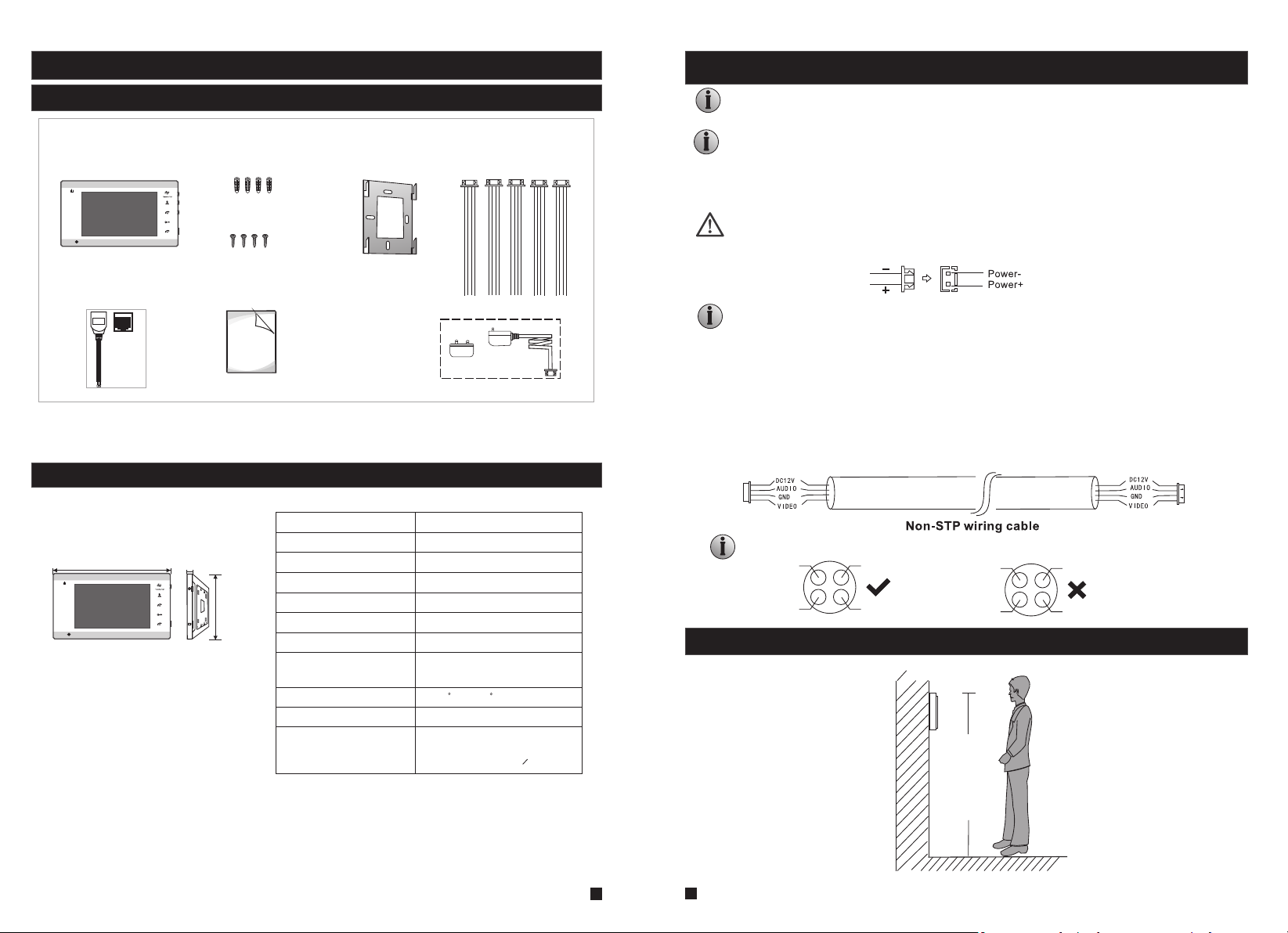
1.1 Fittings
For indoor monitor
Indoor monitor
(1pcs)
1
2
A Network Conversion
Line with 4 pin interface
(1pcs)
LAN
Monitoring
Talk
Unlock
Hang up
1.2 Specifications
236mm
1
2
14mm
Monitoring
Talk
Unlock
Hang up
Screw anchors
(4pcs)
Wall screws
(4pcs)
User Manual
(1pcs)
OPERATION INS
142mm
TF
IP Villa Video Intercom Sys
Quick Guide
Display screen
Definition
Standard
Calling mode
Calling time
Standby current
Work current
Power supply
Bracket
(1pcs)
External Switching
Power Adapter--DC
12V(1pcs)--Optional
4 Pin line
(5pcs)
7"TF T LCD screen
1024(H)X600(V)
PAL/NTSC
Two-way conversation
120s
Maximum 400MA
Maximum 800MA
DC 12V
The electric lock/source/camera is not include in the package, you can purchase an electric
lock which is suitable for your need.
In the standard delivery the system supports locks with Normally Open (N.O.) door unlocking
method. It means that in the normal state the dry contact is opened so the lock is kept under
constant closed state. If the unlocking push-button is pressed and the dry contact is changed
to closed, then the lock is released.
Please check that the socket of power supply(silk printing J8) is correct if you connect
the external switching power supply, otherwise it will damage the device.
Please note the silk printing marked on PCB in order to avoid incorrect connecting.
The wiring connection requirement(The actual effect and the quality of wire rod has
the very big relations):
1. 4C ordinary non-STP wiring cable;
2. Effective distance from the outdoor camera to furthest indoor monitor:
Transmission ≤30m (4x0.4mm )
Transmission ≤60m (4x0.65mm )
2
2
If you want to extend the distance over 60m, you'd better to choose a thick copper core
cable.
Wiring connection according to the following to avoid interference:
Power+ Video
Audio
GND
Power+ Video
GND
Audio
1.4 Installation Process
Work temperature
Installation way
Extension memory
-10 C~+60 C
Surface mounting
TF card
(maximum 64GB )(>CIass 10)
150-160cm
5
6
Note
※
The indoor mon ito r with built-in p owe r supply can be connec ted d irectly to the pl ug
or connected t o the p ower box.
※
The doorbell i s sup plied from Indo or Mo nitor.
※
The door lock ne ed it s additional po wer s upp ly, the po wer supply of the l ock i s not
supplied fro m the d oorbell or the in doo r monitor.
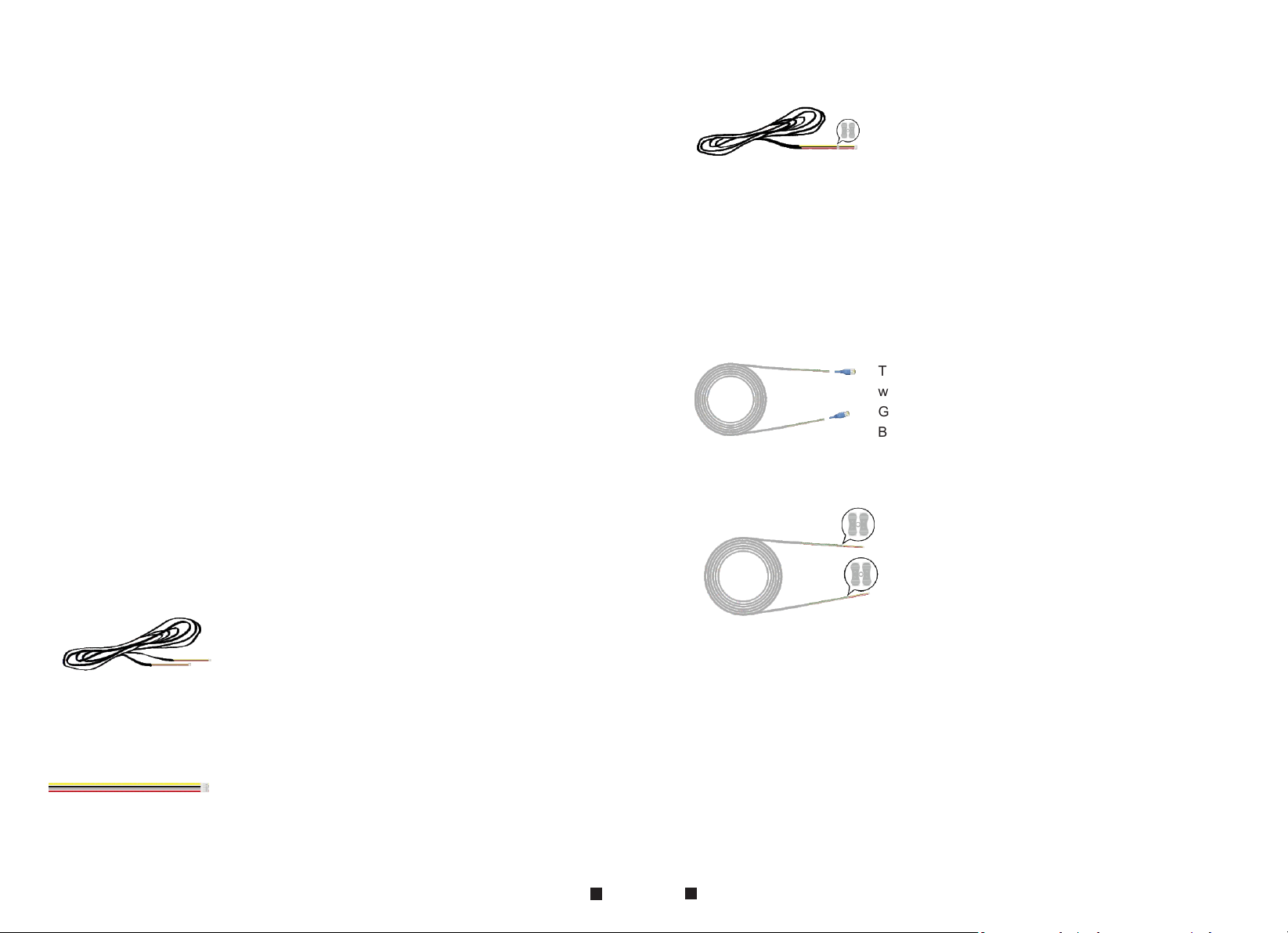
About Extension cables
If your 4 core cable doesn’t built with the white terminal,
you can connect with the 4 pin connector we provided
in the box and then connect to the monitor.
White terminal
Cat5,cat6 network extension cables
We don’t provide the extension cables in the box.
You can use the RVV4(4 core cable) or cat5/cat6 to extend
the distance between the monitor-doorbell,monitor-monitor,
or doorbell-doorbell.
If you want to extend the distance over 50m,even 100m,
it is better for you choose a thick core cable.
Please see below:
To extend the distance between the monitor-doorbell,
monitor-monitor, or doorbell-doorbell.
RVV4 (4 core cable)
extension cables
Cat5, cat6 network cable
Cut the RJ45 port.
There are 8 wires(4 pairs) in the cat5/cat6, we let two
wires twisted into one cable to use.
Green+green&white, Orange+orange*white,
Blue+blue&white, Brown+brown&white
Connect with the 4 pin connector we provided
in the box,please make sure the 4 wires
connections at both ends are consistent.
4 Pin connector
(provided in the box)
If the extension cable you have is not built with 4 pin connector
or the connector of the cable you have is different from our
4 pin connector, you should cut the cable and connect the cable
to our 4 pin connector provided in the box, then connect it to
the monitor.
7
8
NOTE:
* Avoid installation of the device near strong radiation e.g. TV set and PC etc.
* Maintenance should be complied with a qualified technician.
* Avoid hard shake , beating and collision, otherwise the internal exact components
maybe be damaged .
* Select the most suitable position where the monitor is located at user's eye level.
* Switch off power supply before installing.
* Keep more than 30cm away from AC power supply to avoid external interference.
* Keep it away from the water and magnetic field.
To install the indoor unit, please follow these steps as below:
cables
Screw anchors
Bracket
Screws
1
2
Monitoring
Talk
Unlock
Hang up
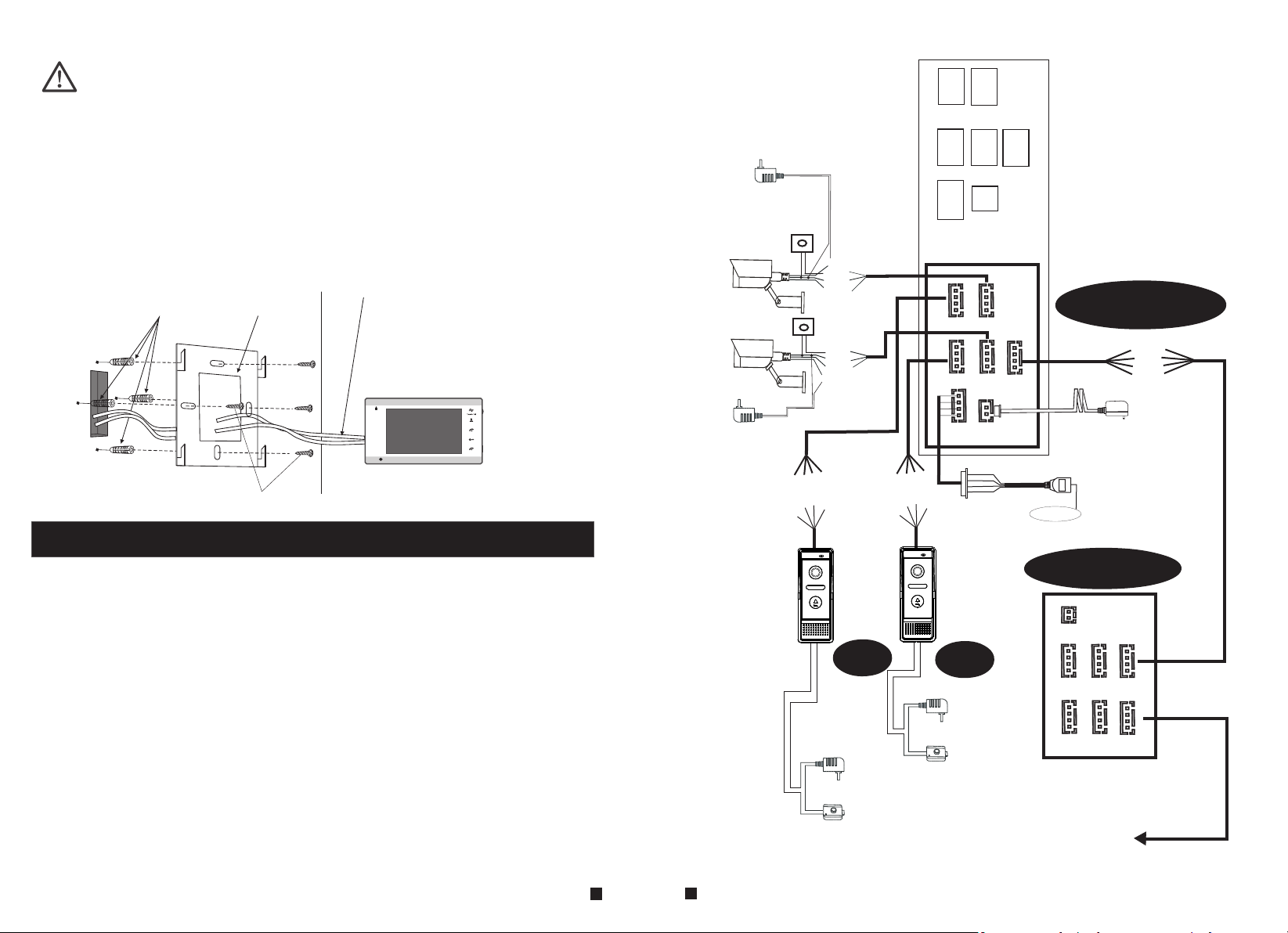
1.5 Wiring Diagram
AC/DC power
adapter for
camera
(not included)
CAM1
CAM2
AC/DC power
adapter for
camera
(not included)
VCC
VCC
AUDIO
ALM
GND
GND
VIDEO
VIDEO
CAM 1
DOOR1
VCC
VCC
ALM
GND
VIDEO
CAM 2
GN
VCC
DC 12V
AUDIO
GND
DATA
VIDEO
OUT
D
AUDIO
GND
VIDEO
DOOR2
Rx-
Rx+
Tx
-
T
x
+
M1
L
A
2V
1
C
D
M
L
A
D
N
G
eo
d
i
V
LAN
IP Indoor Monitor
CAM 1
M2
L
A
M
L
A
D
N
G
o
de
Vi
2V
1
DC
o
o
D
V
i
e
2
d
N
d
1
i
u
G
V
C
A
D
DOOR1
AUDIO
GND
DATA
DOOR2
RX-
RX+
TX-
TX+
LAN
CAM 2
DC 12V
OUT
External switching
VIDEO
power supply DC 12V
o
o
D
V
i
e
2
d
N
d
1
i
u
G
V
C
A
D
LAN
Internet
For 7'' indoor monitor, user can connect up to 2 CVBS outdoor doorbells & 2 CVBS CCTV
cameras, three extendable indoor monitor(one by one) to the corresponding interfaces by
their own’s requirement according to the following wiring diagram. The ethernet connector
is a 4 pin connector, user needs to connect a network conversion with 4 pin interface to
it(shown as below for example).
Note: 1. The indoor monitor uses an external switching power supply.
2. The CCTV cameras must use an external power supply.
Indoor monitor
TV-out
DOOR1
AC/DC power
adapter
for unlocking
(not included)
AC/DC
electric lock
(not included)
9
10
DOOR2
AC/DC power
adapter
for unlocking
(not included)
AC/DC
electric lock
(not included)
CAM 1
DOOR1
CAM 2
DOOR2
next Slave
IN
OUT
1.6 Alarm Instructions
Name
Descriptions
CAM1 and CAM2 of this production have each an alarm function. When the trigger terminal and
GND is shorted, the alarm is activate, the indoor monitor will emit alarm sound, the alarm ring time
is according to the menu option “Alarm->CAM1 ring time/CAM2 ring time. During this time, press
“ ” to stop alarming and enter the standby mode.
Hang up
Connection diagram:
Be app licable t o connect 2 n ormally c losed (NC ) or norm al ly open ( NO ) alarm i np uts.
2 came ra channe ls of alarm i nput with out limit ation s on i nput ty pe ( can eit he r be the
norm ally open t ype or the no rmally cl osed type ).
ALM te rminal of t he alarm de tector is c onnecte d in parall el with t he AL M termi na l (The
alar m detecto r shall be su pplied by e xternal p ower su pp ly).
Grou nd termin al of the ala rm detect or is conne cted in par allel w it h the GND t er minal o f
the ca mera.
For NO a larm inpu ts, when th e GND and ALM ar e in the conn ection st ate, it w il l trigg er
the al arm.
For NC a larm inpu ts, when th e GND and ALM ar e in the disc onnec t st ate, it w il l trigg er
the al arm.
It app lys to any al arm senso r.
Switch power adapter
for camera(not included)
CAM
2V
C1
D
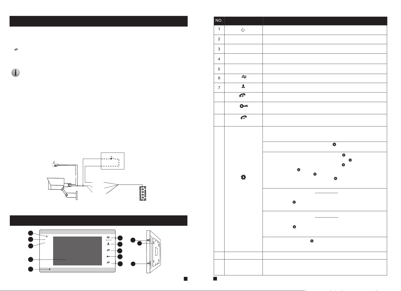
1.7 Description On Indoor Monitor
1
2
3
4
5
1
2
GN
A
D
M
L
M
AL
D
GN
o
de
i
V
6
11
13
11
12
TF
Monitoring
Unlock
Hang up
7
8
Talk
9
10
12
13
9
10
8
11
1
2
TFT display
Microphone
Transfer call
Monitoring
Talk
Unlock
Hang up
Setting
Speaker
TF card slot
Power LED, the power indicator of the indoor monitor.
The do or 1 state li ghts, to do or 1 workin g when the LE D is on.
The do or 2 state li ghts, to do or 2 workin g when the LE D is on.
View visitor ’s image displayed on the TFT screen.
Transmit the voice to outdoor camera.
Intercom call or transfer calls to another indoor monitor.
Watch the door and camera images.
Activate conversation mode by pressing this button.
Release the door lock.
Hang up or return button on menus.
1. The button is a composite key, users can press the button, scroll
the button upward or downward. For more details, please refer to
the section “Menu Operations”.
2. In standby mode, press the button “ ” once to quickly access the
menu.
3.
In main menu settings, scroll the button “ ” upwards or
downwards to select sub-menu, then press “ ” again to enter
sub-menu. In sub-menu settings, press “ ” to select menu
options, scroll “ ” upwards or downwards to adjust values of
each option, then press “ ” to confirm. When select option
“Return” on the main menu, press “ ” to exit menu interface,
and the indoor device will be into standby mode.
4. When the menu option on section 5.3.6 “Parameters->Event->
Record->Record mode” set up as “Snapshot”, in monitoring/talking
mode, press “ ” to capture a frame of the current video stream as
a still photo manually.
5. When the menu option on section 5.3.6 “Parameters->Event->
Record->Record mode” set up as “Record”, in monitoring/talking
mode, press “ ” to start manual record, and press this button
again to stop manual record.
6. In talking mode, scroll “ ” upwards or downwards to adjust the
communication volume of the indoor monitor.
Sound from outdoor camera.
For the mod el s wi th TF car d, i ns er t th e TF ca rd f or v id eo r ecord s an d
photogr ap hs , su pp orts up t o 64 GB . And s ug gest that i t’ s be tter to use a T F
card more t ha n cl as s 10 o nto the d ev ic e.
11
12
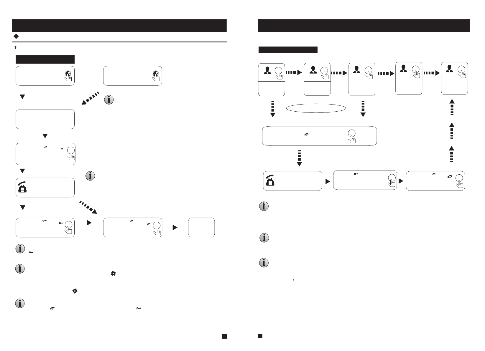
1.8 Operation Introduction On Indoor Monitor
Monitoring
VISITOR CALL
Please be aware of Connection of 2 outdoor cameras is required.
Standby mode
The Visitor press
the call button on
outdoor camera 1
A continuous ring tone
is heard inside and
outside
The visitor’s image
automatically displayed on
the screen
If both call button on two outdoor camera are pressed at approximate
to the same time, the preference will be given to the outdoor camera
which call button was pressed first, unless the call button is pressed
again after the indoor monitor go into standby mode, please be aware
of that there is no indication on second outdoor camera .
Press the “ ”
Talk
Talk
button on indoor
monitor
Stop ringing
Start conversation
with outdoor camera
The indoor unit will automatically go into standby mode if you are not
at home or have not reached the indoor unit in 60s.
The conversation
duration is 120s
at a time
Press the “ ”
button on indoor
monitor
Unlock
Unlock
release the
door lock
Both the visitor's voice and image will not be switched off within 20s of time span when the
“ ” button is pressed, this individualized function allow you to make sure whether the
Unlock
visitor already come in.
When the doorbell record for the video mode, from the start of a call, the whole process will
be recording. If the user press the icon “ ”, the recording will be stopped manually.
the doorbell record for the snapshot mode,
camera, the first picture will be captured in the built-in storage of the indoor monitor,
can press the button “ ” to capture an image.
In monitoring mode, user can hear the sound transmitted from the outdoor doorbell, user can press
the button “ ” to conversation and press the button “ ” to unlock.
The Visitor press
the call button on
outdoor camera 2
NOTICE:
NOTICE:
Press the “ ”
button on indoor
monitor.
if a visitor press the call button on the outdoor
Hang up
Hang up
End
hang up
When
user
Option in the settings in the menu: DOOR1, CAM1, DOOR2, CAM2 operating mode (open or closed)
Standby Mode
Show DOOR1
image
Show CAM1
image
Each monitoring time is 60S
Show DOOR2
image
Show CAM2
image
Close LCD
Press the “ ” button
Call Outdoor
Press the “ ” button
on the indoor unit, the
electric lock will be opened.
Press the “ ”
button to end
the call.
Hang up
Hang up
NOTICE:
If you are using only one outdoor camera in monitoring mode, you can also end the
monitoring mode by pressing the monitoring button again(Must be Close CAM1;
DOOR2; CAM2 in the menu option).
If you use two indoor units, you can also simultaneously in other indoor unit
starts monitoring mode, the same images are displayed on the screen of
the different indoor unit.
If a conversation with outdoor unit is underway in monitoring mode, during
this time a visitor press the call button on either of outdoor unit, the
monitoring mode will be switched off, the just visitor’s image will appear on
its screen and continuous ringing will be heard. If you are using the indoor
unit with hands-free, you can press the talking button to reactivate
conversation with the visitor.
13
14
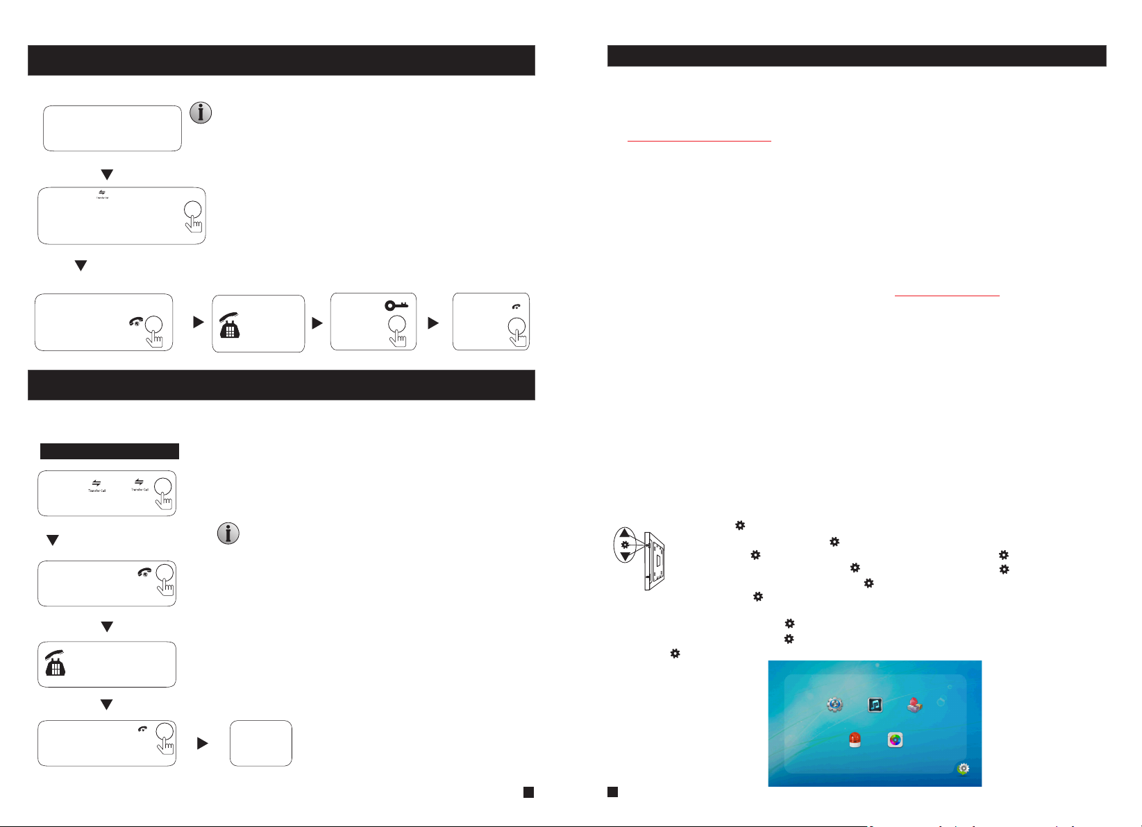
Call Transfer To Other Extension
Internal communication function requires at least two indoor and one outdoor units to be connected.
Outdoor camera call indoor
monitor and conversation
is underway
NOTICE:
When you are transferring a call to other extension, the original
conversation indoor unit will return to standby mode, and the
indoor unit which the call is being transferred will also sound a
continuous ring tone and the video image will appear on its
Press the “ ” button
screen.
to activate the function of
call transfer to other
extension.
A continuous ring
tone is heard
Press the talk
button on any of
indoor units
Talking
with visitor
The Electric
lock can
be opened
End the call
and return to
standby mode.
Internal Communication Among Indoor monitors
At least 2 indoor units is required.
Standby Mode
Press the “ ”
button
A continuous ring tone
is heard
Press the talk
button on any of
indoor units
Start conversation
among indoor units.
NOTICE:
In internal communication mode, if a visitor press the call
button on either of outdoor unit, the internal communication
mode will be switched off. The just visitor' s image will appear
on its screen and continuous ringing will be heard, you can
press the talk button to reactivate conversation with the
visitor.
Hang up
2. Menu Operations On Indoor Monitor
Attention before using:
1. This indoor monitor includes OSD menu on it’s own device, users could set up some
parameters on the indoor monitor.
2.1 Mouse Control
2. User can connect the device through web browser on PC, please refer to section
“3. Web Browser Operation”.
3. Also user can connect the indoor monitor through mobile phone/tablet with the
“uCareHome” app, please refer to “uCareHome app for IP Indoor Monitor User Manual”.
4. The motion detection function only supports for one channel, it means that when
activating motion detection function of the Door 1, the motion detection function of the
other channel can’t be activated at the same time. User can set up the motion detection
parameters through IE browser or the “uCareHome” app.
5. The TF card can be formatted remotely via the “uCareHome” app or through IE browser,
the file system of the TF card must be FAT32.
6. The TF card will be used to store video record or snapshot when calling on the outdoor
bell, please refer to the configuration on section “5.3.6 Event-Record”.
7. When all the button LEDs is flashing, the indoor monitor is ready in AP mode.
8. When unlocking, the app unlock time is set separately from the monitor ’s own unlock
time. If unlock from the app “uCareHome”, the unlock time of Door1 and Door2 are the
same, will be consistent with the menu option value “Device Information->Unlock Time”.
If unlocking on the monitor, the unlock time of Door1 and Door2 can be different, will be
consistent with the menu option value “Mode->Door1 unlock time/Door2 unlock time”.
9. If users don’t do any operate or enter any interface about the indoor monitor, the indoor
monitor will be into standby mode after 1 minute automatically.
10. When the menu option “Key backlight” is set to “ON”, when user presses any button or
some visitor calls on the outdoor doorbell, all back-light LEDs of the button will be on. If
the indoor monitor is in standby mode, if user doesn’t do any operate on the device in 10
seconds, the back-light of each button will be off.
11. During editing parameters on the monitor, the red characters indicate that the option
has been selected. When the red characters flash, it indicates that the option is in edit state.
In standby mode, press the button “ ” to access the main menu interface, shows the main interface
as shown below. On menus, scroll “ ” upward or downward to move the cursor to the option “Return”,
then press “ ” to exit; or press “Hang up” to return.
The button “ ” is a three-in-one key, but also composite keys:
In standby mode, press the button “ ” once to enter the main menu settings. In main menu settings,
scroll the button “ ” upward or downward to select sub-menu, then press “ ” again to enter
sub-menu. In sub-menu settings, press “ ” to select menu options, scroll “ ” upward or downward
TF
to adjust values of each option, then press “ ” to confirm. When select option “Return” on main menu,
press the button “ ” to exit menu interface, or press “Hang up” button, the indoor monitor will be
into standby mode.
Press Hang
up button
Hang up
End
Syste m Ring Mo de
Alarm C olor
15
16
Retur n
 Loading...