

TME MM2030 Operating Instructions Manual
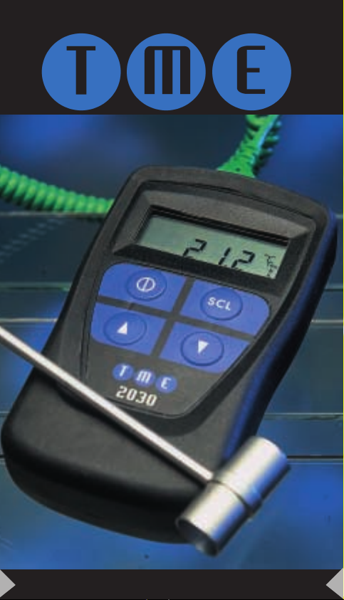
MM2030
Handheld Thermometer
3
MM2030
2
GB
English
OPERATING INSTRUCTIONS
To Measure Temperature
1. Fit the battery to the instrument
(refer to battery replacement details)
2. Switch thermometer ON.
3. Plug thermocouple into input socket.
4. Check temperature scale is correct.
(°C / °F/ °A)
5. Check thermocouple is correct
6. Take measurement by contacting object with probe and
reading from the display.
Changing Temperature Scale (°C / °F/ °A)
To change the temperature scale simply press the button
marked ‘SCL’
The temperature scale will alter as shown on the right
hand side of the display.
Changing Thermocouple Type
To change thermocouple type, follow the sequence below:
1. Switch the unit OFF.
2. Press and hold the ‘SCL’ button.
3. Switch the unit ON.
4. Release buttons.
Note
MilliVolt function is selected as if it were a thermocouple
type.
The new thermocouple type will appear in the bottom
right hand corner of the display (see fig 1). Repeat steps
above until desired thermocouple type is shown.
Introduction
Your high accuracy microprocessor driven thermometer is
suitable for use with thermocouple types K,J,T,R,N,E,S or
Infra-Red sensors.
The thermocouple calibrations are in accordance with
national and international standards (NBS and IEC) tables.
Features
•
°C / °F/ °A
TEMPERATURE SCALES
•
MEASURE TEMPERATURE
•
SIMULATE THERMOCOUPLE
•
OVERRANGE / OPENCIRCUIT PROBE INDICATION
•
LOW BATTERY INDICATION
•
K,J,T,R,N,E,S THERMOCOUPLE TYPES
•
Milli-Volt MEASUREMENT OUTPUT.
•
RETENTION OF THERMOCOUPLE TYPE AND SCALE
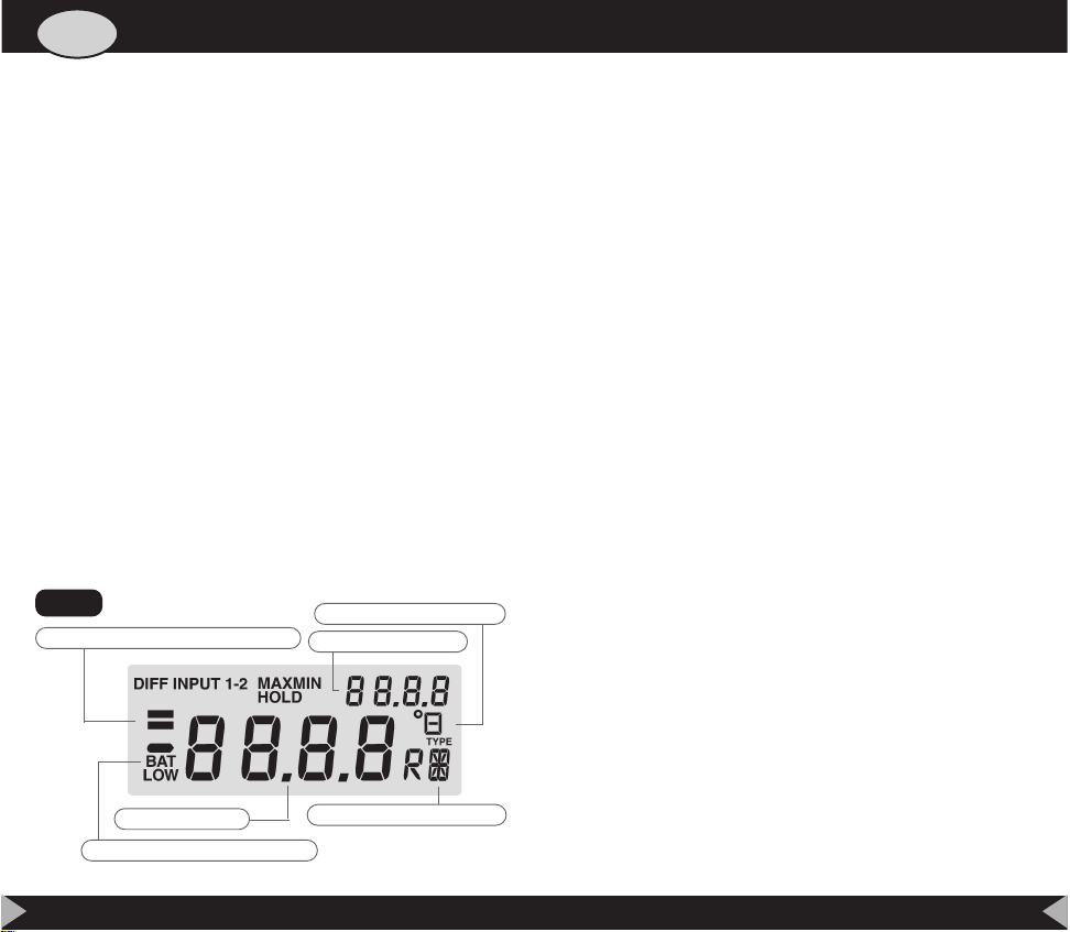
MAIN DISPLAY
THERMOCOUPLE TYPE
SECOND DISPLAY
SIMULATION INDICATOR BARS
BATTERY LOW INDICATION
TEMPERATURE SCALE
fig 1

5
MM2030
4
Replacing The Battery
The instrument will indicate ‘BAT LOW’ when the battery
needs changing.
To change the battery, firstly remove the unit from the
outer case. The battery compartment is on the rear of the
instrument. Using a small screwdriver ease back the tab
of the battery compartment. The compartment will then
lift away.
Open Circuit Thermocouple Detection
An error in the probe is shown on the display by a series
of bars ‘- - - - -’ coupled with the word ’INPUT’ at the top
of the display. This indicates either that the probe has an
error or the temperature is out of range.
Simulate Thermocouple
This instrument is capable of simulating a thermocouple,
thus enabling it to be used to check the calibration
accuracy of any other thermocouple instrument/controller.
To change to the simulate mode press both arrow keys
simultaneously. Simulate mode is indicated by a solid bar
on the left of the display. To cancel this mode, simply
press both arrow keys again. When in simulate mode, the
set point is shown on the main display and may be
changed using the arrow keys. The second display
indicates the actual output of the unit. When the two are
equal the output has settled and as a further guide a
second bar is activated in the left of the display.
To avoid cold junction errors, the test equipment and the
simulator should be at the same ambient temperature.
K
T
R
N
J
E
S
mV
-200ºC to 1372ºC
-200ºC to 400ºC
-50ºC to 1767ºC
-200ºC to 1300ºC
-200ºC to 1200ºC
-200ºC to 1000ºC
-50ºC to 1767ºC
-328ºF to 250ºF
-328ºF to 752ºF
-58ºF to 3212ºF
-328ºF to 2372ºF
-328ºF to 2192ºF
-328ºF to 1832ºF
-58ºF to 3212ºF
-10 to 70mV
-73ºF to 1645ºF
-73ºF to 673ºF
-223ºF to 2040ºF
-73ºF to 1573ºF
-73ºF to 1473ºF
-223ºF to 1273ºF
-223ºF to 2040ºF
CENTIGRADE FAHRENHEIT KELVIN
ELECTRICAL
Measurement Ranges
Accuracy@23ºC ±0.15% of reading ±0.2ºC
Characterising error less than 0.05ºC
Temperature coefficient 0.01% of reading/ºC
Cold junction compensation 0.0075ºC/ºC
Resolution 0.1ºautoranging to 1º 1000º
Note
Strong RF fields may adversely affect measurement accuracy.
General
WEIGHT 155 gms (5.47 oz)
DIMENSIONS 130 x 70 x 33 mm
BATTERY PP3
BATTERY LIFE 200 Hours
SPECIFICATIONS
Environmental
Ambient operating range -30°C to 50°C (-21 to 122°F)
Storage temperature range -40°C to 60°C (-40 to 140°F)
Humidity 0 to 70% R.H.
6
Introduction
Ce thermomètre de haute précision à microprocesseur est
conçu pour fonctionner avec des thermocouples de type
K, J, T, R, N, E, S ou des capteurs d’infrarouge.
L’étalonnage des thermocouples s’effectue conformément
aux tableaux publiés dans les normes américaines (NBS) et
internationales (IEC).
Caractéristiques générales
•
ÉCHELLES DE TEMPÉRATURE
°C / °F/ °A
•
MESURE DE TEMPÉRATURES
•
SIMULATEUR DE THERMOCOUPLE
•
INDICATION DE DÉPASSEMENT DE LIMITE / SONDE
EN CIRCUIT OUVERT
•
INDICATION DE PILE FAIBLE
•
TYPES DE THERMOCOUPLES K, J, T, R, N, E & S
•
SORTIE EN MILLIVOLTS POUR SIMULATION DE
MESURE
•
MÉMORISATION DU TYPE DE THERMOCOUPLE ET
DE L’ÉCHELLE
7
MM2030
FR
François
NOTICE D’UTILISATION
Pour mesurer une température
1. Montez la pile dans l’instrument (voir les instructions de
remplacement de la pile).
2. Mettez le thermomètre sous tension (ON).
3. Branchez le thermocouple dans la prise d’entrée.
4. Assurez-vous d’avoir sélectionné la bonne échelle de
température
(°C / °F/ °A)
.
5. Assurez-vous d’avoir sélectionné les bons types de
thermocouple.
6. Prenez la mesure en mettant la sonde en contact avec
l’objet et en lisant la valeur qui s’affiche.
Changement d’échelle de température
(°C / °F/ °A)
Pour changer d’échelle de température, appuyez sur le
bouton marqué ‘SCL’.
L’indicateur d’échelle de température, sur la droite de
l’afficheur, permet de constater que l’échelle a changé.
Changement de type de thermocouple
Procédez comme suit pour changer de type de
thermocouple :
1. Mettez l’instrument hors tension (OFF).
2. Appuyez sur le bouton ‘SCL’ et maintenez ce dernier
enfoncé.
3. Mettez l’instrument sous tension (ON).
4. Relâchez les boutons.
Remarque:
On sélectionne la fonction MilliVolt
comme s’il s’agissait d’un type de thermocouple.
Le nouveau type de thermocouple apparaît en bas à droite de
l’afficheur (voir figure 1). Recommencez les étapes ci-dessus
jusqu’à voir s’afficher le type de thermocouple désiré.
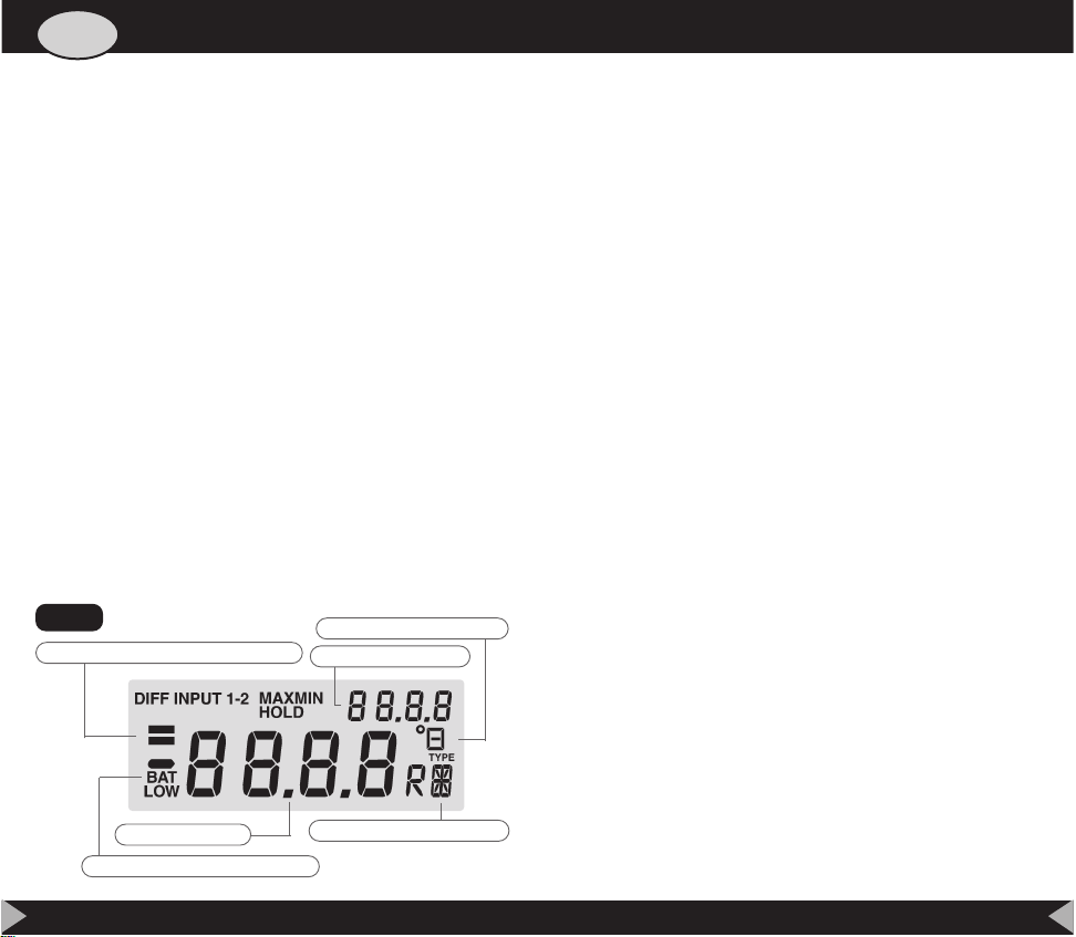
MAIN DISPLAY
THERMOCOUPLE TYPE
SECOND DISPLAY
SIMULATION INDICATOR BARS
BATTERY LOW INDICATION
TEMPERATURE SCALE
fig 1
 Loading...