

TMC Radio P25 SRP9100, SRM9022-P25, SRM9030-P25 Operating Instructions Manual

P25 SRP9100
Portable Radio
P25 - Conventional
Operating Instructions
TNM-U-E-0073 V1.1b
TMC Radio Pty. Ltd.
1270 Ferntree Gully Road
Scoresby
Victoria, 3179
Australia
ISO9001 Lic.QEC2 0848
SAI G lobal

SRP9100 RADIO P25 – OPERATING INSTRUCTIONS
ASSOCIATED DOCUMENTATION
The following documentation is available for use with the SRP9100 series of products:
TNM-U-E-0070 P25 SRP9100 Portable Radio Brief User
Guide
To order copies of any of the above publications, or any other TMC Radio product, contact
TMC Radio on +61 3-9730-3800 or send a Fax on +61 3-9730-3968.
The TMC Radio web site also has a comprehensive list of documentation available for
download.
http://www.tmcradio.com
ABOUT THIS DOCUMENT
This publication is copyright and no part may be reproduced without prior permission of TMC
Radio.
Due to our policy of continuous improvement to our products and services, technical
specifications and claims, correct at time of publication, may be subject to variation without
prior notice.
TMC Radio has endeavoured to ensure that the information in this document is fairly and
accurately stated, but does not accept liability for any errors or omissions.
© TMC Radio 2007 Page 2 TNM-U-E-0073 1.1b

SRP9100 RADIO P25 – OPERATING INSTRUCTIONS
SAFETY
1. Do NOT operate your radio in an explosive atmosphere.
Obey the 'Turn Off Two-way Radios' signs where these are posted, e.g. on a
petrol station forecourt.
2. Do NOT touch the antenna while the radio is transmitting.
HINTS FOR USING THE RADIO
• When speaking, hold the radio a few centimetres from your mouth and speak across it,
rather than into it.
• Keep the length of your conversation to a minimum.
© TMC Radio 2007 Page 3 TNM-U-E-0073 1.1b

SRP9100 RADIO P25 – OPERATING INSTRUCTIONS
CONTENTS
1. INTRODUCTION .................................................................................................6
1.1 Overview...................................................................................................... 6
1.2 Configuration .............................................................................................. 6
1.3 Modes of SRP9100 P25 Operation ............................................................6
2. CONTROLS......................................................................................................... 7
3. MENU SYSTEM................................................................................................... 9
3.1 Menu Navigation ....................................................................................... 10
4. MENU SCREENS .............................................................................................. 12
4.1 Channel Screen......................................................................................... 12
4.2 Menus ........................................................................................................14
4.2.1 Zone........................................................................................................ 14
4.2.2 Squelch ................................................................................................... 16
4.2.3 Mute Adjust / Monitor .............................................................................. 17
4.2.4 Phonebook .............................................................................................. 18
4.2.5 Phonebook Edit....................................................................................... 20
4.2.6 User Options ........................................................................................... 23
4.2.7 Contrast................................................................................................... 24
4.2.8 Alert Volume............................................................................................ 24
4.2.9 Radio Info................................................................................................25
4.2.10 Mode ....................................................................................................... 26
4.2.11 RSSI........................................................................................................27
4.2.12
Crypto...................................................................................................... 28
4.2.13 Setup....................................................................................................... 29
4.2.14 Stored Calls............................................................................................. 30
4.2.15 Messages................................................................................................ 31
4.2.16 Scan Edit Menu....................................................................................... 39
4.2.17 No Menu.................................................................................................. 41
5. COMMON FUNCTIONS AND FACILITIES ....................................................... 42
5.1.1 Switch-On/Switch-Off ..............................................................................42
5.1.2 Default Screen –Trunked Mode ..............................................................42
5.1.3 Volume Adjustment .................................................................................42
5.1.4 Receiving (Single Channel Screen) ........................................................ 43
5.1.5 Received Individual Calls ........................................................................ 43
5.1.6 Stored Calls Screen ................................................................................ 44
5.1.7 Received Call Pop-Up Menu ................................................................... 44
5.1.8 Transmitting ............................................................................................45
5.1.9 Scan/Vote Functions ............................................................................... 45
5.1.10 Keypad Lock ...........................................................................................46
5.1.11 Encryption ............................................................................................... 47
5.1.12 Emergency Alarm.................................................................................... 47
6. SPECIAL FUNCTION KEYS .............................................................................49
© TMC Radio 2007 Page 4 TNM-U-E-0073 1.1b

SRP9100 RADIO P25 – OPERATING INSTRUCTIONS
6.1 Alarm ......................................................................................................... 49
6.2 Announce .................................................................................................. 49
6.3 Channel Up and Down.............................................................................. 49
6.4 Crypto ........................................................................................................49
6.5 DTMF Send 1/2 .......................................................................................... 49
6.6 Low Power................................................................................................. 49
6.7 Menu .......................................................................................................... 49
6.8 Mode .......................................................................................................... 49
6.9 Mute ........................................................................................................... 49
6.10 Reset ......................................................................................................49
6.11 RSSI........................................................................................................49
6.12 Scan ....................................................................................................... 49
6.13 Scan Edit................................................................................................50
6.14 Scrambler............................................................................................... 50
6.15 Skip ........................................................................................................ 50
6.16 Squelch .................................................................................................. 50
6.17 Talkaround............................................................................................. 50
6.18 Zone .......................................................................................................50
7. ALERT TONES AND MESSAGES.................................................................... 51
8. GLOSSARY....................................................................................................... 52
9. COMPLIANCE WITH RF ENERGY EXPOSURE GUIDELINES .......................53
© TMC Radio 2007 Page 5 TNM-U-E-0073 1.1b

SRP9100 RADIO P25 – OPERATING INSTRUCTIONS
1. INTRODUCTION
1.1 OVERVIEW
The Simoco SRP9100 Series Radios are a family of versatile Digital Signal Processor (DSP)
controlled, software-defined two-way portable radios.
These Operating Instructions describe the operation of the APCO P25 Standard compliant
Portable Radio, with suffix P25. There are two versions of the model, one with a keypad
(SRP9130) and one without a keypad (SRP9120).
The SRP9100 P25 Radio may be customised to your operational requirements using the
Field Personality Programmer (FPP). Your Simoco representative can help in programming
your radio facilities to meet your present and future requirements.
1.2 CONFIGURATION
The SRP9100 P25 Radio must be configured using the P25 Field Personality Programmer
(FPP) prior to operation. The configuration process defines the radio channels, signalling and
other settings so that the radio will operate with your system.
1.3 MODES OF SRP9100 P25 OPERATION
The SRP9100 P25 Radio operates in Analogue FM and P25 Conventional and Trunked
Digital modes.
Radio Channels are organised in groups of up to 250 per zone. Up to 64 zones may be
defined.
Generally, zones can be programmed with channels belonging to common function groups.
A radio channel can be defined as either Analogue, Conventional P25 Channel or Trunked
P25 network, and a Zone may contain a mix of Analogue or Conventional P25 Channels.
© TMC Radio 2007 Page 6 TNM-U-E-0073 1.1b
SRP9100 RADIO P25 – OPERATING INSTRUCTIONS
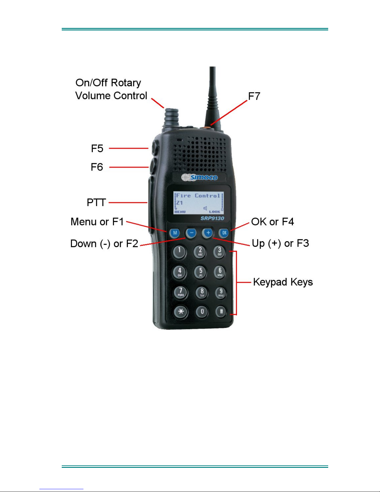
2. CONTROLS
Figure 1 – SRP9130 Portable Key Layout
© TMC Radio 2007 Page 7 TNM-U-E-0073 1.1b
SRP9100 RADIO P25 – OPERATING INSTRUCTIONS
SRP9100
Key/Control
Label Function
On/Off / Volume
The portable radio is turned on by rotating the volume
knob clockwise, and turned off by rotating it anticlockwise.
Turning the knob clockwise increases volume.
PTT
Push-to-Talk. Hold the radio 10cm from the mouth.
Press and hold the PTT switch and speak. Release
to listen.
Function Key F1
M
Programmable Function key.
Default – Menu Select.
Function Key F2
Programmable Function key.
Default – Channel Down.
Function Key F3
Programmable Function key.
Default – Channel Up.
Function Key F4
Programmable Function key.
Default – OK.
Function Key F5
Programmable Function key.
Function Key F6
Programmable Function key.
Default – Reset / Cancel.
Function key F7
Programmable Function key.
Default – Alarm.
Keypad
1 2 3
4 5 6
7 8 9
* 0 #
Keypad can be used to select a Channel or Special
Function.
Eg. 12# will select channel 12.
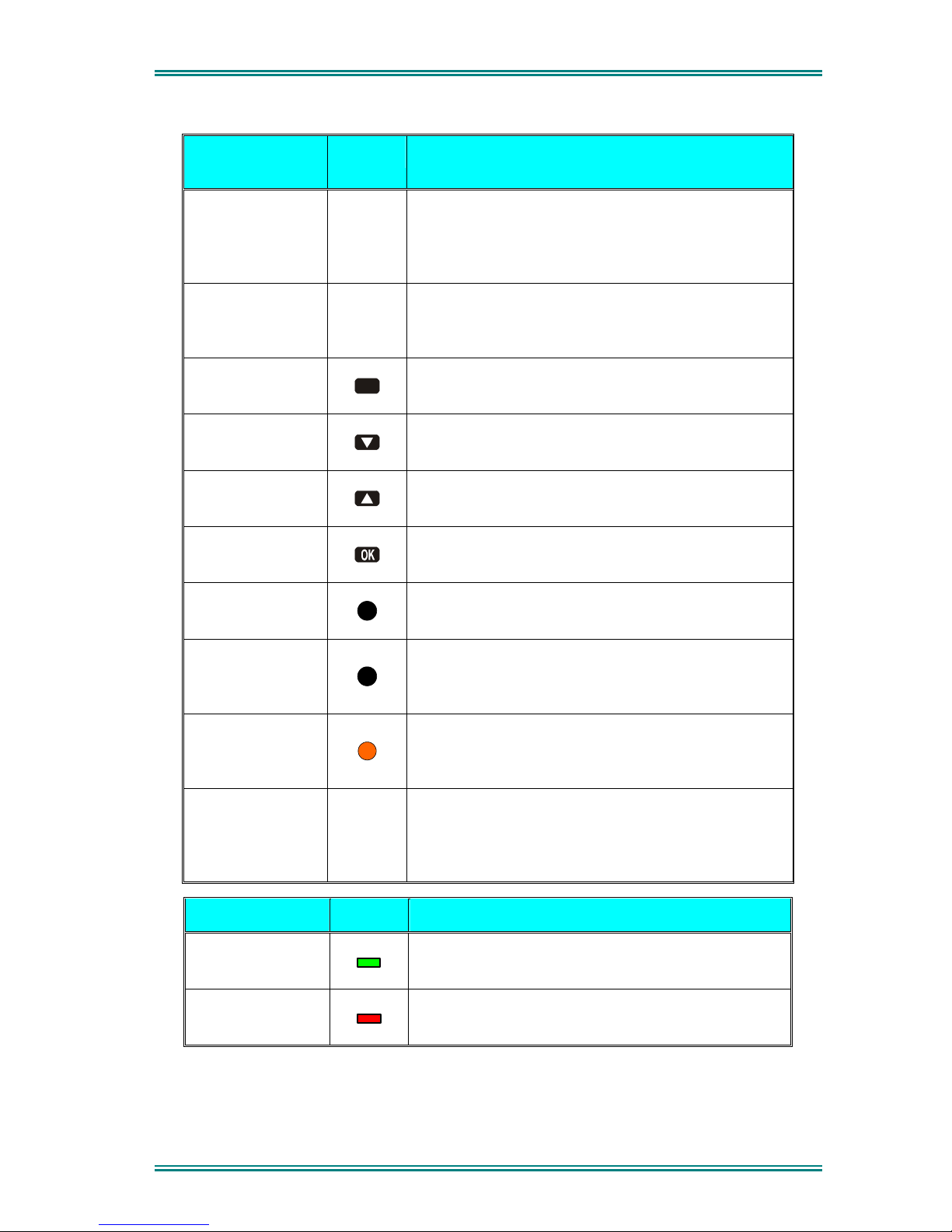
Indicator LED Function
Green
Green LED when receiving a signal.
Red
Red LED when the radio is transmitting.
© TMC Radio 2007 Page 8 TNM-U-E-0073 1.1b

SRP9100 RADIO P25 – OPERATING INSTRUCTIONS
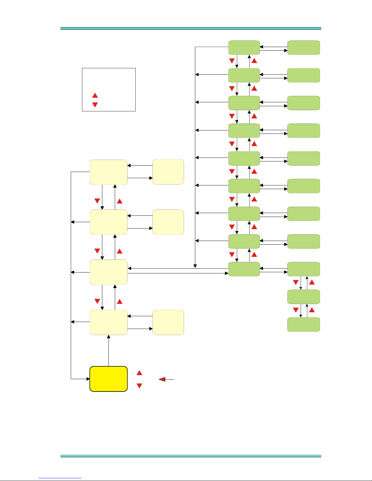
3. MENU SYSTEM
The SRP9100 P25 portable radio uses a menu structure for access to all of the radio
features and functions. The structure of the menu can be programmed to meet the specific
needs of individual customers.
Figure 2 illustrates the menu structure of the radio. Note that the order and presence of each
menu is determined by the configuration of the radio programmed by the Field Programmer.
Possible Menu entries are:
• Zone (usually the first menu, as accessed often)
• Squelch
• Mute Adjust (FM) / Monitor (Digital)
• Phonebook
• Phonebook Edit
• User Options
• Contrast
• Alert Volume
• Radio Info
• Mode
• RSSI
• Crypto
• Setup
• Stored Calls
• Messages
• Scan Edit
• No Menu
To assist the user in menu key selection, a soft menu label may appear above the function
keys. The label shows the user the current function for that key which may change between
different menus.
Programming of menus is a configuration task normally performed by the system manager
using the FPP software.
© TMC Radio 2007 Page 9 TNM-U-E-0073 1.1b

SRP9100 RADIO P25 – OPERATING INSTRUCTIONS
3.1 MENU NAVIGATION
Pressing the “M” key selects Menu mode from the main Channel Screen. Once in menu
mode, the ▼ and ▲ keys cycle through the menus.
To exit Menu mode, press the “M” key again or the Menu timeout will exit automatically.
Generally, pressing “M” key while in a menu backs up to the next highest level of menu and
the “OK” button selects the menu screen.
The ▼ and ▲ keys are used to navigate through a list of options such as channels, or
increase/decrease a value.
When the Menu key is first pressed, the numeric keys become short cut keys to functions.
Numeric keys can be programmed (using FPP) with functions i.e. Scan.
To access this, you can press the “M” or menu key from the channel screen and then the
numeric key assigned to that function.
© TMC Radio 2007 Page 10 TNM-U-E-0073 1.1b
SRP9100 RADIO P25 – OPERATING INSTRUCTIONS
Normal
Channel
Screen
Zone Select
Menu #1
Setup Menu
(Optional)
(Optional)
Menu #2
Menu #3
Menu #3
Menu #x
Menu #x
Select
Zone
ENTRY POINT = Default Screen
Channel
Note:
Example Menus only shown.
P25 Conventional Menu rev1d
Other Menus may be configured with the FPP
Up Key
Down Key
Back Key
OK Key
Squelch
Mute
Adjust
SubMenu Selections
RSSI
Mode
Radio Info
Crypto Key
Alert
Volume
Contrast
User Options
Submenu
Submenu
Submenu
Submenu
Submenu
Submenu
Submenu
Submenu
Key Beeps
ON/OFF
Backlight
ON/OFF
(Other User
Menu items)
Back
OK
Menu
OK
OK
OK
OK
OK
OK
OK
OK
OK
BackBack
BackBack
BackBack
Back
Back
OK
BackBack
Back
OK
BackBack
Back
Back
OK
BackBack
Back
Back
OK
BackBack
BackBack
BackBack
Figure 2 - Menu Navigation
© TMC Radio 2007 Page 11 TNM-U-E-0073 1.1b
SRP9100 RADIO P25 – OPERATING INSTRUCTIONS
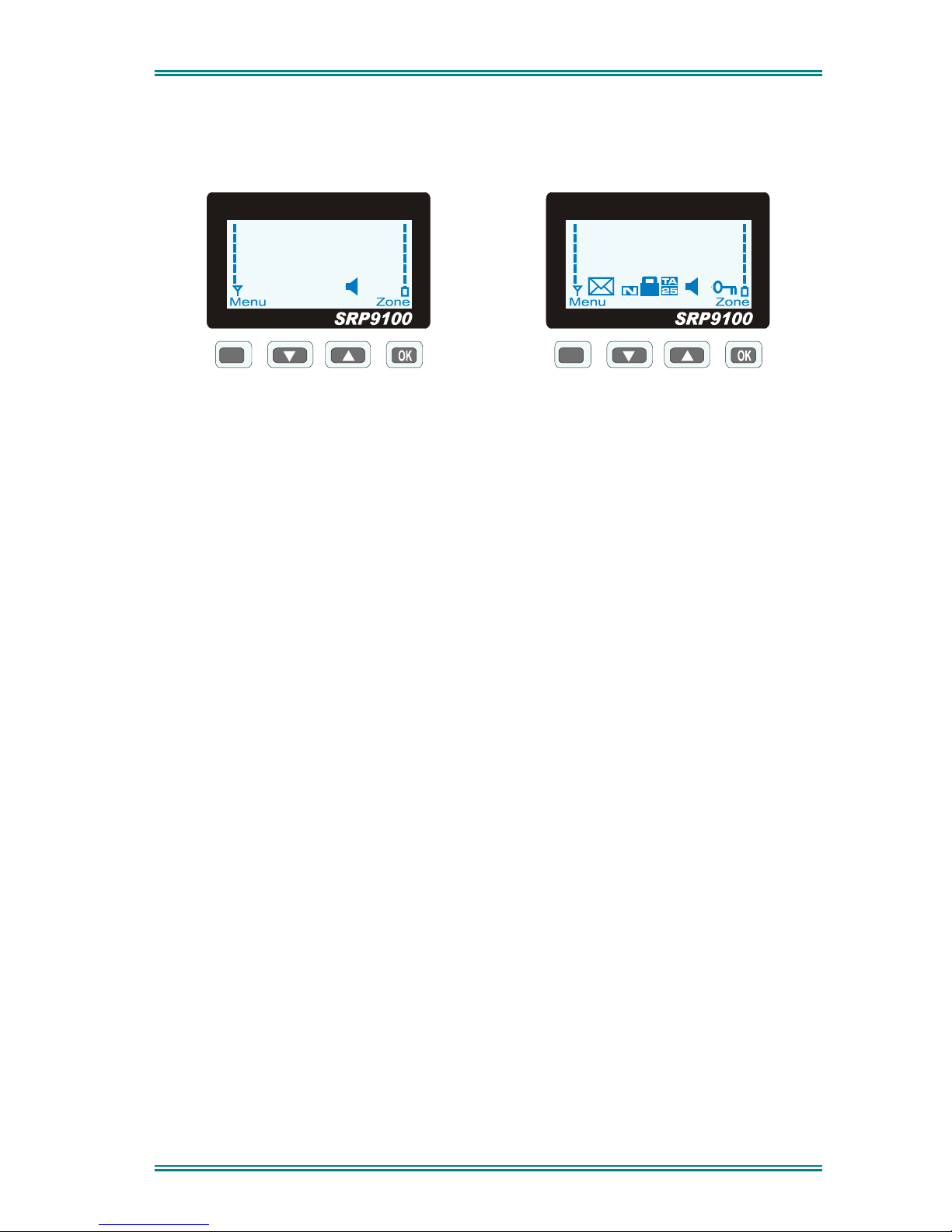
4. MENU SCREENS
4.1 CHANNEL SCREEN
M
Special Ops
Zone 4
Typical Display
M
Icons
The Channel Screen shows the current channel and allows channel selection.
The Channel Name (top line) shows the text associated with the currently selected radio
channel.
The Zone Name (middle) shows the text associated with the currently selected radio zone.
The RSSI Bars indicate the signal strength of the current channel.
The Battery Bars indicate the battery charge level.
Pressing the “M” key enters the Menu mode.
The lower part of the screen is reserved for icons.
Radio channels may be configured with the Field Programmer as specific frequencies or as
auto scan types. When an auto scan channel is selected, it will immediately go into scan
mode. Selecting another non-autoscan channel will stop the scan.
If a radio channel is defined as a P25 Conventional Digital Channel, it will only receive P25
digital signals.
If a radio channel is defined as an Analogue FM channel, it will receive both P25 Digital* and
Analogue FM signals.
* While in Analogue mode, all unencrypted digital P25 traffic will be heard regardless of NAC
or Talkgroup.
© TMC Radio 2007 Page 12 TNM-U-E-0073 1.1b
SRP9100 RADIO P25 – OPERATING INSTRUCTIONS
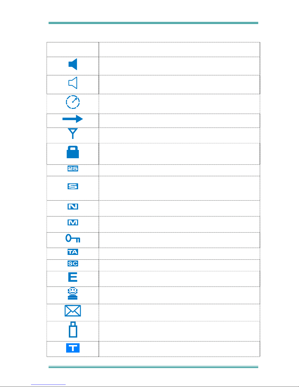
ICONS INDICATION
A filled speaker indicates that a signal is present and the audio can
be heard from the speaker
The outline speaker icon indicates that a signal is present and the
radio is muted. This could be another user group, for instance
Scan Indicator. When radio is on a scan channel and scanning, the
arrow will rotate
Transmit Indicator
Received Signal Strength Indication (RSSI). A stronger signal will
display more bars above the “antenna” icon
Encryption Indicator. The icon is shown when the selected channel is
programmed for encryption. If an unencrypted signal is received, the
icon will be not be displayed.
25 = Digital Mode Indicator
Selective Mute. Only radio signals specifically directed to the user or
the channel’s defined talkgroup will be heard on the speaker
Normal Mute. Only radio signals from the users own network will be
heard on the speaker
Monitor. All P25 digital radio signals on the channel will be heard
All keys except PTT, or any function assigned as Alarm, will be
disabled. Press the OK key for 2 seconds to unlock all keys
Talk Around enabled indicator. When shown, Talk Around is active
Scrambler indicator (analogue only)
Emergency mode. Blinking icon indicates that the emergency button
has been pressed.
Individual Addressing Mode. When shown, the radio will transmit to
an individual address instead of a talkgroup
Envelope icon. Indicates that a message(s) stored if icon steady,
icon flashes if unread message(s) stored.
Battery charge indicator. 6 vertical bars above the icon show the
battery state of charge.
Trunking mode. Icon is shown when a trunking system has been
selected.
© TMC Radio 2007 Page 13 TNM-U-E-0073 1.1b
SRP9100 RADIO P25 – OPERATING INSTRUCTIONS
C
Connecting icon. Shown when a text message is being sent and the
connection is in progress
!
Connection Fail icon. Shown when a text message transmission has
failed.
4.2 M
ENUS
The menu structure on the SRP9100 is configurable using the Field Programmer. A system
administrator usually tailors the order and presence of the menu options to specific customer
requirements.
This section will describe all the possible menus.
Normally the menus are divided into two menu lists.
These are normally the Main menu list and the Setup menu list.
In the default configuration, the Main menu contains the Zone screen and a Setup screen.
This allows access to the second “Setup” menu level.
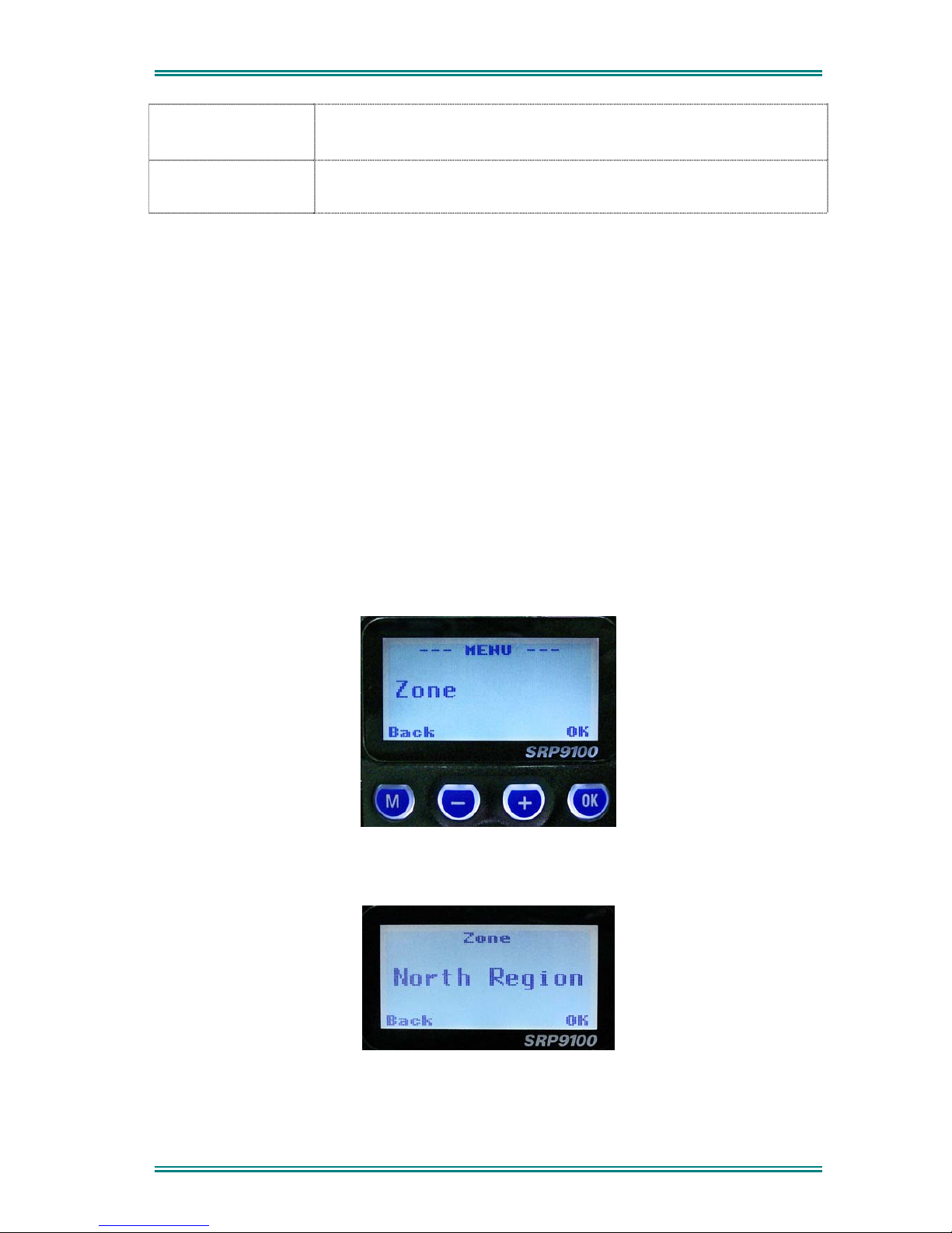
4.2.1 Zone
The Zone Screen is used for changing Zones. A Zone is normally defined as a group of radio
channels with a common operational role.
When the “Zone” menu option is displayed, press the “OK” button to enter the “Zone“ select
screen.
Once the “Zone” menu appears, press the ▼ and ▲ keys to choose the required Zone.
Press the “OK” key to select the required Zone. The radio will return to the channel screen
and select the first channel in the new Zone.
© TMC Radio 2007 Page 14 TNM-U-E-0073 1.1b

SRP9100 RADIO P25 – OPERATING INSTRUCTIONS
Direct access to the “Zone” menu from other screens can also be programmed to one of the
function buttons with the Field Programmer.
© TMC Radio 2007 Page 15 TNM-U-E-0073 1.1b
SRP9100 RADIO P25 – OPERATING INSTRUCTIONS
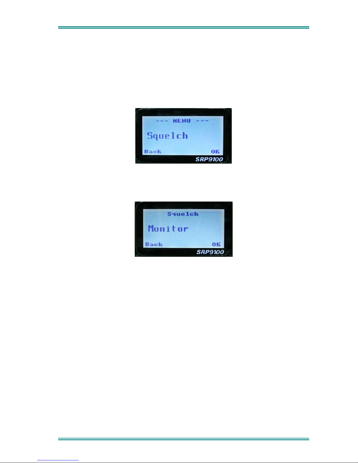
4.2.2 Squelch
This menu allows the channel’s default squelch mode to be modified.
If the selected channel is changed or the radio is switched off, the channel’s default squelch
setting will be restored.
Press the “OK” key for the “Squelch” Menu
P25 Squelch Screen
For a P25 digital channel, pressing the ▼ and ▲ keys will allow selection of either Monitor,
Normal or Selective squelch mode.
For an analogue channel, pressing the ▼ and ▲ keys will allow selection of either Monitor
or Normal squelch mode.
Digital Channel Monitor Mode:
The radio will receive any decryptable or clear P25 digital voice signals. The Network Access
Code (NAC) is not checked. An “M” icon on the display indicates monitor mode.
Digital Channel Normal Mode:
When Normal squelch is selected, the radio will receive all decryptable or clear digital
transmissions with the correct NAC. Reception is not conditional upon the talkgroup or Unit
ID. An “N” icon on the display indicates normal squelch.
Digital Channel Selective Mode
If Selective squelch is chosen, the radio will only receive decryptable or clear digital
transmissions with the correct NAC and Talk Group ID (TGID) or correct NAC and Unit ID.
An “S” icon indicates selective squelch.
© TMC Radio 2007 Page 16 TNM-U-E-0073 1.1b
SRP9100 RADIO P25 – OPERATING INSTRUCTIONS
Analogue Channel Monitor Mode:
The radio will receive any Analogue voice or P25 digital signals. Digital NAC or Analogue
CTCSS is not checked. An “M” icon indicates monitor.
Analogue Channel Normal Mode:
When Normal mute is selected, the radio will receive correctly addressed Analogue radio
transmissions and all decryptable or clear digital transmissions. An “N” icon indicates
Normal.
Pressing the “OK” key returns to the main channel screen.
Pressing the “Back” or “M” key returns to the next highest menu level
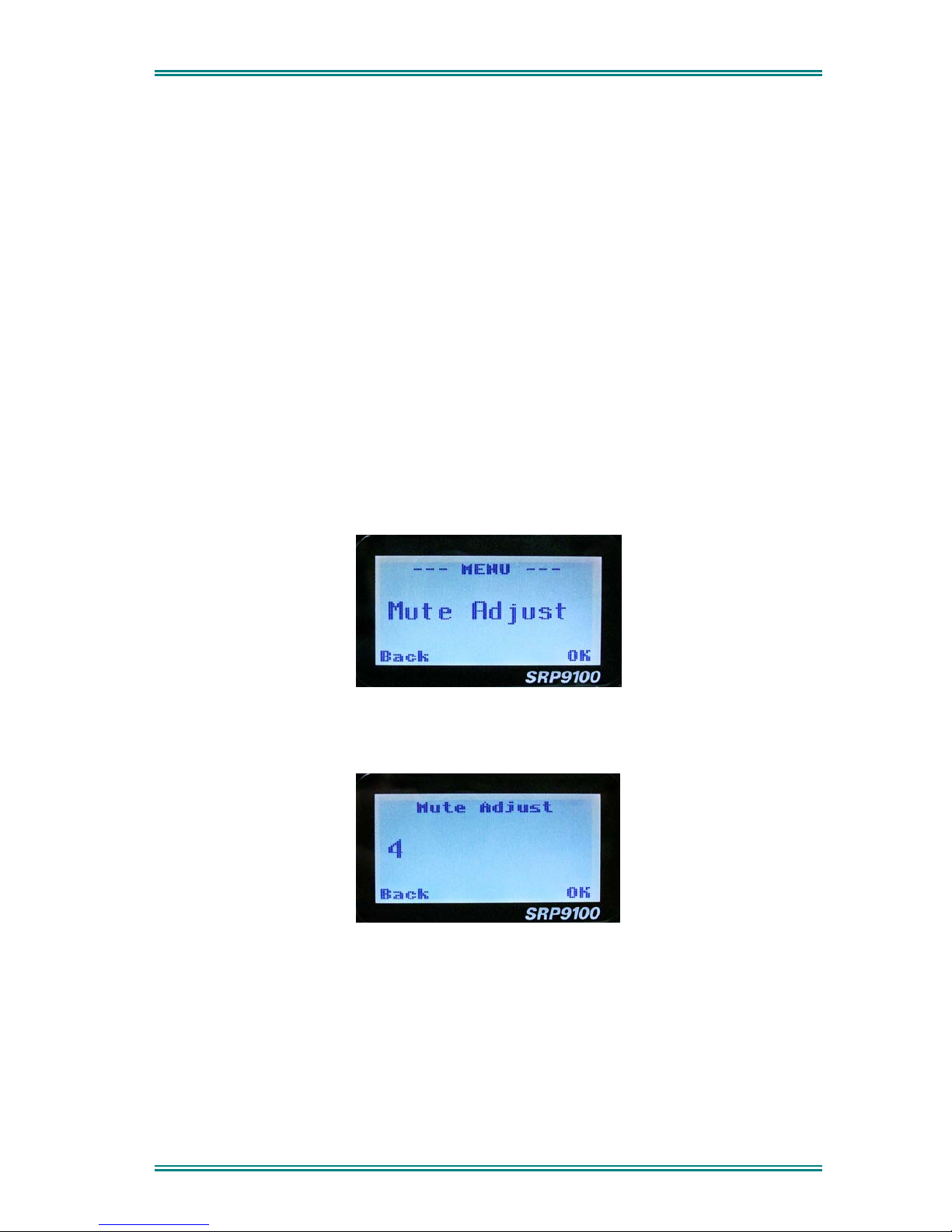
4.2.3 Mute Adjust / Monitor
From the menu list, step through the menu options with the ▼ and ▲ keys until the “Mute
Adjust” menu is displayed.
Press the “OK” key for the Mute adjustment screen.
Analogue Mute Screen
The mute adjustment will be applied to all the radio’s analogue channels.
Use the ▼ and ▲ keys to adjust the mute threshold. A numeric value of the present mute
level is shown.
The “OK” key returns to the default channel screen with the selected mute setting.
It is recommended that the default mute setting of 4 be used. The SRP9100 series radios
have a carrier noise mute and this means the mute will open at the point where an analogue
signal is sufficiently noise free to be intelligible with a setting of 4.
© TMC Radio 2007 Page 17 TNM-U-E-0073 1.1b
 Loading...