

TMC Radio SRM9022 Operating Instructions Manual
SRM9022
Mobile Radio
Trunked MPT
Operating Instructions
TNM-U-E-0068 Issue 2
May 2006
TMC Radio Pty. Ltd.
1270 Ferntree Gully Road
Scoresby
Victoria, 3179
Australia
ISO9001 Lic.QEC20848
SAI Global

SRM9022 ~ TMR MOBILE RADIO USER GUIDE
© TMC Radio 2006 page 2 TNM-U-E-0068 Issue 2
ASSOCIATED DOCUMENTATION
The following documentation is available for use with the SRM9000 series of
products:
TNM-I-E-0005 SRM9000 Series Installation Instructions
TNM-M-E-0001 SRM9000 Service Manual
TNM-U-E-0012 SRM9020 Trunked Operating Instructions
TNM-U-E-0013 SRM9020 PMR Operating Instructions
TNM-U-E-0003 SRM9030 PMR Operating Instructions
TNM-U-E-0004 SRM9030 Trunked Operating Instructions
TNM-U-E-0065 SRM9022 PMR Operating instructions
To order copies of any of the above publications, or any other TMC Radio product,
contact TMC Radio on +61 3-9730-3800 or send a Fax on +61 3-9730-3968.
ABOUT THIS DOCUMENT
This publication is copyright and no part may be reproduced without prior permission
of TMC Radio.
Due to our policy of continuous improvement to our products and services, technical
specifications and claims, correct at time of publication, may be subject to variation
without prior notice.
TMC Radio has endeavoured to ensure that the information in this document is fairly
and accurately stated, but does not accept liability for any errors or omissions.

SRM9022 ~ TMR MOBILE RADIO USER GUIDE
© TMC Radio 2006 page 3 TNM-U-E-0068 Issue 2
SAFETY
1. Do NOT operate your radio, without a handsfree kit, whilst driving a
vehicle.
2. Do NOT operate your radio in an explosive atmosphere.
Obey the 'Turn Off Two-way Radios' signs where these are posted, e.g.
on a petrol station forecourt.
3. Do NOT touch the antenna while the radio is transmitting.
4. Do NOT operate the radio if the antenna has become disconnected or
damaged.
HINTS FOR USING THE RADIO
• When speaking, hold the microphone a few centimetres from your mouth and
speak across it, rather than into it.
• Keep the length of your conversation to a minimum and replace the microphone
on its cradle after use.
• When it is possible to move location, avoid making calls from known poor signalstrength areas such as the radio systems fringe areas (limit of range) or from
screened or shadowed areas, e.g. an underground car park or underpass.
• To avoid unnecessary drain on the vehicle battery, keep the engine running when
using the radio for extensive periods of time.

SRM9022 ~ TMR MOBILE RADIO USER GUIDE
© TMC Radio 2006 page 4 TNM-U-E-0068 Issue 2
CONTENTS
1. INTRODUCTION..................................................................................................6
1.1 Overview......................................................................................................6
1.2 Installation...................................................................................................6
1.3 Conventions ................................................................................................6
2. FRONT PANEL CONTROLS...............................................................................7
3. MENU SYSTEM...................................................................................................8
3.1 Menu navigation..........................................................................................8
4. MAIN MENU SCREENS ....................................................................................10
4.1 Phonebook Screen....................................................................................10
4.2 Stored Calls Screen..................................................................................11
4.3 Recall Screen.............................................................................................13
4.4 Status Screen............................................................................................13
4.5 Call Types Screen.....................................................................................14
4.6 Setup Screen.............................................................................................14
5. COMMON FUNCTIONS AND FACILITIES ....................................................... 15
5.1 Switch-On/Switch-Off ...............................................................................15
5.1.1 In-Service Indication................................................................................15
5.1.2 Volume Adjustment .................................................................................15
6. CALL TYPES.....................................................................................................16
6.1 Making a Voice Call...................................................................................17
6.1.1 During a Voice Call.................................................................................. 17
6.2 Making a Status Call................................................................................. 18
6.2.1 Using the Phonebook.............................................................................. 18
6.2.2 By Dialling the Numbers..........................................................................18
6.3 Receiving a Call.........................................................................................19
6.3.1 Receiving a Voice Call.............................................................................19
6.3.2 Receiving a Group Voice Call ..................................................................20
6.3.3 Incoming Status and Data Messages......................................................20
6.4 Call Diversion............................................................................................21
6.4.1 From the Call-Types Screen....................................................................21
6.4.2 By Dialling the Numbers..........................................................................21
6.4.3 To Cancel a Diversion............................................................................. 21
6.5 DTMF Operation........................................................................................22
7. SETUP............................................................................................................... 23
7.1 Setup Sub Menus......................................................................................23
7.1.1 User Options............................................................................................23

SRM9022 ~ TMR MOBILE RADIO USER GUIDE
© TMC Radio 2006 page 5 TNM-U-E-0068 Issue 2
7.1.2 Group ......................................................................................................24
7.1.3 Phone Book Edit Menu............................................................................ 24
7.1.4 Contrast................................................................................................... 26
7.1.5 Alert Volume............................................................................................26
7.1.6 Information...............................................................................................27
7.1.7 Network ...................................................................................................27
8. OPTIONS...........................................................................................................28
8.1 Quick Release Transceiver Kit................................................................. 28
8.2 Microphone/Control Head Extension Lead.............................................28
8.3 Parallel I/O Expansion Option (dmap).....................................................28
8.4 Internal GPS Option..................................................................................28
8.5 Cross-linked Cable....................................................................................28
8.6 600 Ohm Interface Option.........................................................................28
8.7 Dual Control Head Option (dmap) ...........................................................28
8.8 Dual Transceiver Option (dmap).............................................................. 28
8.9 Desk Top Base Kit.....................................................................................28
9. TROUBLESHOOTING....................................................................................... 29

SRM9022 ~ TMR MOBILE RADIO USER GUIDE
© TMC Radio 2006 page 6 TNM-U-E-0068 Issue 2
1. INTRODUCTION
1.1 OVERVIEW
The SRM9000 Series Radios are versatile Digital Signal Processor (DSP) controlled,
two-way mobile radios. The SRM9000 Series is available in a number of frequency
bands and versions for specific applications. This manual describes the operation of
the SRM9022 TMR Controller Microphone variant.
The radio consists of a Transceiver unit that may be mounted in the vehicle boot or
under a seat, and a Controller Microphone, which is designed to mount on the
vehicle console or within view and reach of the operator.
The radio is software programmable and can be customised to the operational
requirements of your particular fleet. Your TMC Radio representative can help in
programming your radio facilities to meet your present and future requirements.
This guide describes the facilities that are currently available and can be
programmed into the SRM9022.
1.2 INSTALLATION
As the installation of your SRM9022 Radio is a technical and possibly hazardous
operation, we recommend that it is installed and set up for use by your dealer or an
authorised installer. However, if you need information regarding the correct
procedures for installation, please refer to the SRM9000 Series Installation
Instructions supplied with the radio.
1.3 CONVENTIONS
Where the word “generally” or “may” is used to describe a facility, this operation is an
option that may be enabled with the Radio Field Personality Programmer (FPP).
SRM9022 ~ TMR MOBILE RADIO USER GUIDE
© TMC Radio 2006 page 7 TNM-U-E-0068 Issue 2
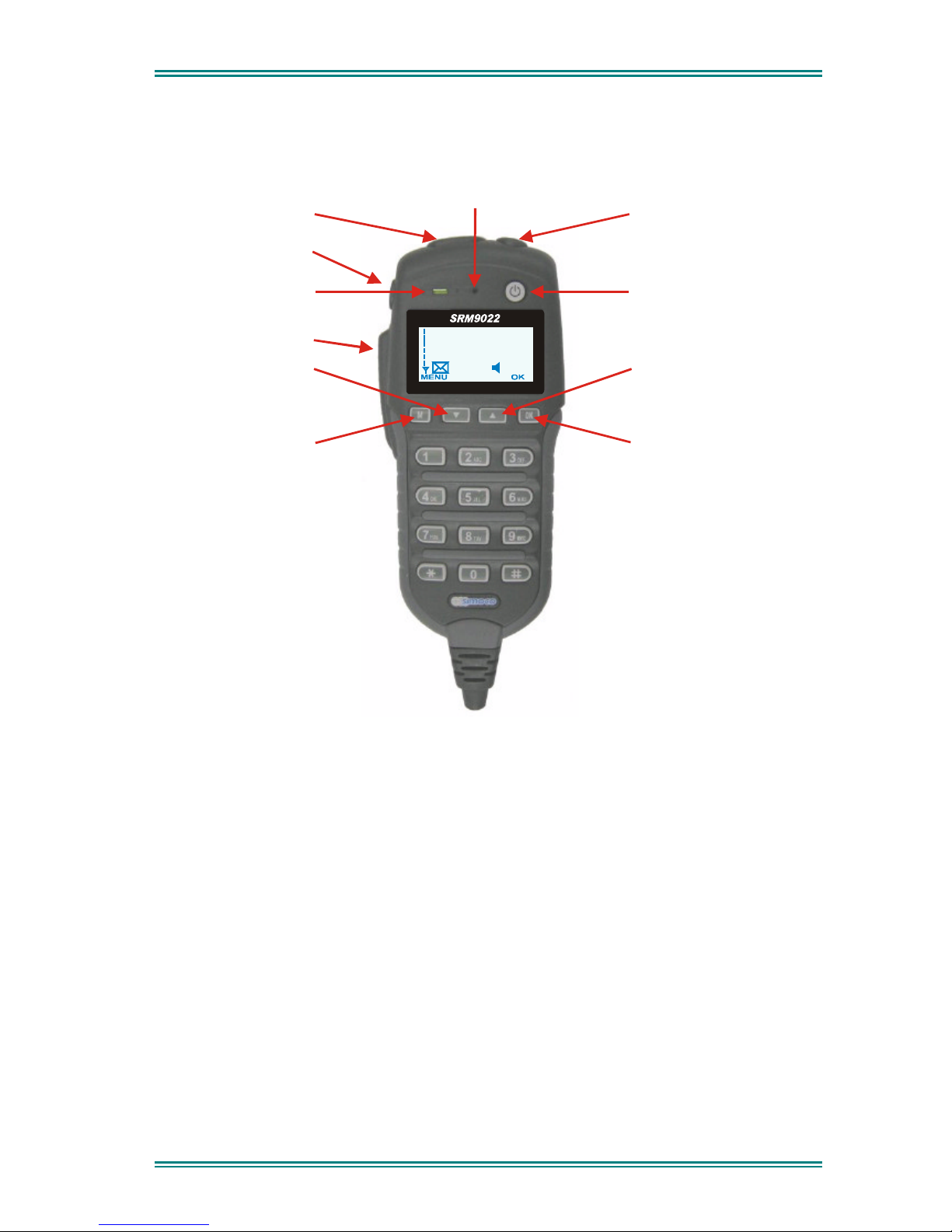
2. FRONT PANEL CONTROLS
Power On/Off
Function #5 (F5)
Volume Up/Down
Function #6 (F6)
RX/TX LED
Microphone
Push To Talk
Menu or
Function #1 (F1)
Function #2 (F2)
Down or
Up or
Function #3 (F3)
OK or
Function #4 (F4)
John Smith
In Service
Figure 2-1 SRM9022 Controller Mic. Key Layout

SRM9022 ~ TMR MOBILE RADIO USER GUIDE
© TMC Radio 2006 page 8 TNM-U-E-0068 Issue 2
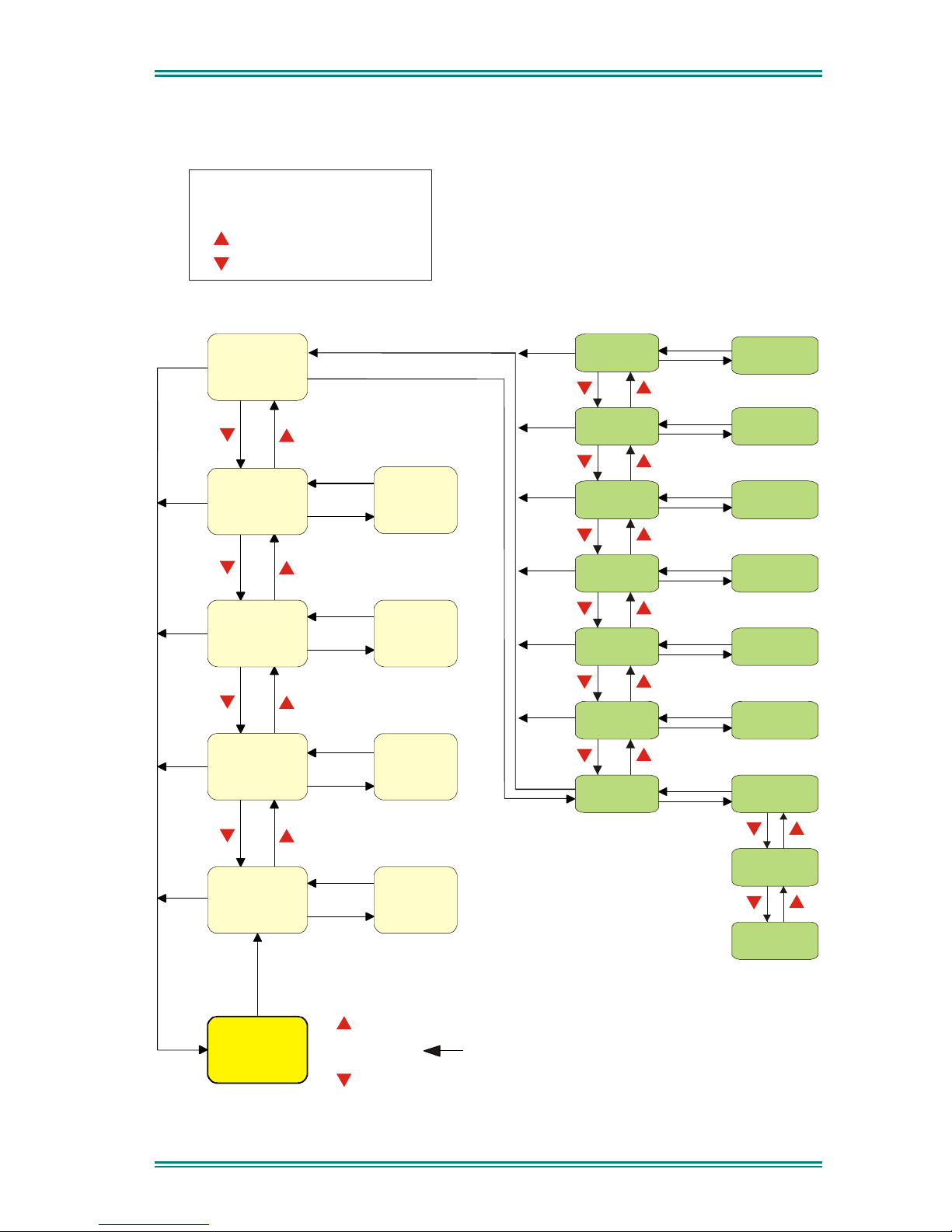
3. MENU SYSTEM
The SRM9022 radio software uses a programmed Menu structure to enable the
operator to access all of the radio options. The structure of the menu (comprising up
to thirteen screens) can be programmed to meet the specific needs of individual
customers. Figure 2 illustrates a complete menu structure of the radios capabilities.
Any or all of the Screens can be programmed or hidden with the following provisos:
The Phone Book Screen is always the default Screen displayed.
The Main Menu provides access to the usual Screens required to operate the radio.
The Setup Sub Menus provides access to the radios setup parameters.
When options are placed in a Setup sub-menu, Setup should be defined as one of
the selections in the Main Menu.
Both the Main Menu and the Setup sub-menus can each hold up to ten Screens.
Programming can allow any menu to be in any position.
3.1 MENU NAVIGATION
The / keys are generally used to navigate through menus, or increase/decrease
a value.
SRM9022 ~ TMR MOBILE RADIO USER GUIDE
© TMC Radio 2006 page 9 TNM-U-E-0068 Issue 2
Menu System
PHONE
BOOK
Menu
Menu
Menu
Menu
Menu
STORED
CALLS
CALL
TYPES
CALL
TYPES
RECALL
STATUS
SETUP
STATUS
RECALL
STORED
CALLS
ENTRY POINT
Scroll through
Phonebook
Entries
Note:
Example Menus only shown.
MPT1327 TNK Menu rev2
Other Menus may be configured with the FPP
Up Key
Down Key
'M' Key (same as ’BACK’)
OK Key
SubMenu Selections
Edit Menu
Edit Menu
PHONEBOOK
PHONEBOOK
CONTRAST
GROUP
ALERT VOL.
RADIO INFO.
NETWORK.
Menu
Menu
Menu
Menu
User Options
NETWORK
RADIO
INFORMATION
ALERT
VOLUME
CONTRAST
GROUP
KEY BEEPS
ON/OFF
BACKLIGHT
ON/OFF
DTMF
ON/OFF
'M'
OK
Default Screen
OK
OK
OK
OK
OK
OK
OK
'M'
'M'
'M''M'
'M''M'
'M'
OK
'M''M'
'M'
'M''M'
'M'
OK
OK
OK
'M''M'
'M'
'M'
'M'
'M'
'M'
'M'
'M'
OK
'M''M'
Figure 2 - Menu Navigation
SRM9022 ~ TMR MOBILE RADIO USER GUIDE
© TMC Radio 2006 page 10 TNM-U-E-0068 Issue 2
*
4. MAIN MENU SCREENS
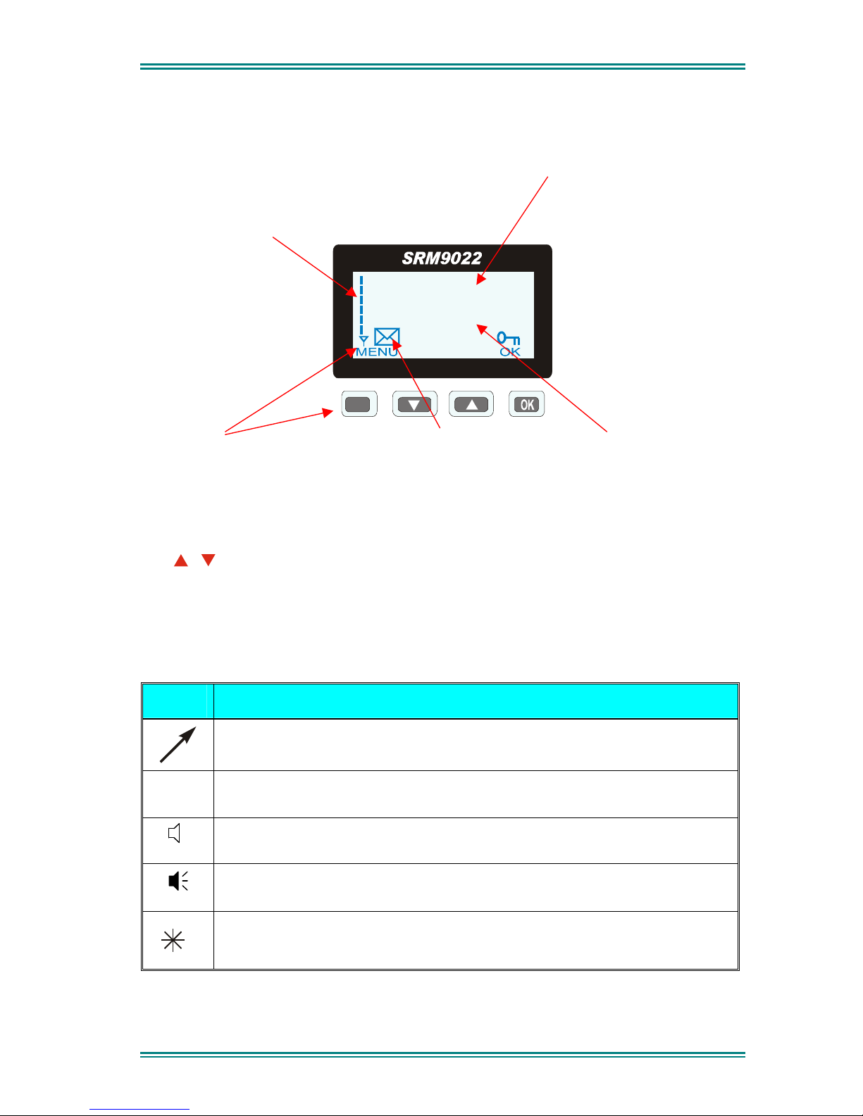
4.1 PHONEBOOK SCREEN
The Phonebook allows calls to be made to entries from the Phonebook list.
The RSSI Bars indicate
the signal strength of the
current Control or Traffic
channel.
The Name Field shows
the current selected entry
from the Phonebook.
M
John Smith
In Service
Displayed Labels show the
function of the F1& F4
buttons. Pressing one of
these buttons will execute
the function.
The ICON Line displays
various icons as
described
in the table below.
The Message Line
provides information about
what the radio is doing, e.g.
Call-setup, Queued,
Diverted, etc.
The / buttons may be pressed to scroll through the Name Field entries.
Press the OK (call) key to call the Name Field entry.
The Keypad may be used to enter dialstrings directly.
Several Icons can be displayed as shown below:
ICONS INDICATION
The rotating arrow icon shows that the radio is registering with the Trunk
Network. It disappears when the radio is in-service.
The envelope icon indicates that there are one or more stored calls, (in
the Stored Calls menu).
The outline speaker icon indicates that speaker audio is muted, e.g.
during Call Setup, NPDs, etc.
The solid speaker icon indicates that speaker audio is enabled, eg
during a Call.
This icon indicates Call Pending, i.e. there is an outgoing call waiting for
the radio to be In-Service.
 Loading...