

TMC Radio SRM9000X8 Service Manual

SRM9000X8 800MHz Mobile
Radio Transceiver
Revision 2 Hardware
SERVICE MANUAL
TNM-M-E-0022
ISSUE 1.0
January 2008
ISO9001 Lic.QEC20848
SAI Global

SRM9000X8 800MHz Mobile Radio Transceiver Rev 2 Hardware TNM-M-E-0022 Iss. 1.0

SRM9000X8 800MHz SERVICE MANUAL
TABLE OF CONTENTS
APPENDICES ..............................................................................................................................................III
DECLARATION .......................................................................................................................................... IV
COPYRIGHT ............................................................................................................................................... IV
ERRORS AND OMISSIONS....................................................................................................................... IV
DOCUMENT HISTORY................................................................................................................................ V
WARNINGS AND CAUTIONS.................................................................................................................... VI
1. INTRODUCTION.................................................................................................................................1
1.1 G
1.2 S
1.3 D
1.4 P
1.5 A
1.6 C
1.7 SPECIFICATION...............................................................................................................................10
2. SERVICE PHILOSOPHY..................................................................................................................19
2.1 S
2.2 W
2.3 S
3. TECHNICAL DESCRIPTION............................................................................................................21
3.1 R
ENERAL
COPE
ESCRIPTION
RODUCT VARIANTS AND FACILITIES
1.4.1 Filename Structure ...................................................................................... ..........................4
1.4.2 Application Code ...................................................................................................................4
1.4.3 Software Type Code..............................................................................................................4
1.4.4 Version Number.................................................................................... .................................6
1.4.5 Exclusions..............................................................................................................................6
1.4.6 Displaying Software Ve rsions..................................................... ...........................................6
1.4.7 Automatic Version Upgrade Prompting.................................................................................7
1.4.8 Transceiver SW Description, Start-up and Backup-Software ...............................................8
1.4.9 Wailing Siren (Boot-up Software Corrupted).........................................................................8
DJUSTMENT AND ALIGNMENT
HASSIS ASSEMBLY
1.6.1 Torque Settings .....................................................................................................................9
1.6.2 Thermal Compound Application............................................................................................9
1.6.3 Assembly...............................................................................................................................9
1.7.1 General................................................................................................................................10
1.7.2 Transmitter...........................................................................................................................11
1.7.3 Receiver...............................................................................................................................12
1.7.4 Signalling.............................................................................................................................13
1.7.5 Environmental......................................................................................................................18
ERVICE CONCEPT
2.2.1 Service Within and Out Of Warranty ...................................................................................19
OFTWARE POLICY
ECEIVER
3.1.1 Front End Filters and RF Amplifier......................................................................................21
3.1.2 First Mixer and IF Section....................................................................................................21
.........................................................................................................................................1
.............................................................................................................................................1
...................................................................................................................................1
................................................................................................2
..........................................................................................................8
.........................................................................................................................9
1.7.4.1 CTCSS.....................................................................................................................13
1.7.4.2 Selcall ......................................................................................................................14
1.7.4.3 DTMF.......................................................................................................................16
1.7.4.4 DCS .........................................................................................................................17
1.7.4.5 C4FM.......................................................................................................................17
.........................................................................................................................19
ARRANTY
....................................................................................................................................19
........................................................................................................................19
......................................................................................................................................21
© TMC Radio 2008 page i TNM-M-E-0022 Issue 1

SRM9000X8 800MHz SERVICE MANUAL
3.1.3 Quadrature Demodulator.....................................................................................................21
3.1.4 Receiver Audio Processing .................................................................................................23
3.2 T
3.3 F
3.4 C
3.5 MEMORY........................................................................................................................................30
3.6 P
4. ALIGNMENT (LEVEL 3 SERVICE ONLY)..................................................... ..................................34
4.1 GENERAL....................................................................................................................................34
RANSMITTER
3.2.1 Drivers and PA Stages........................................................................................................23
3.2.2 Power Control......................................................................................................................24
3.2.3 Antenna Changeover and Harmonic Filter.................. ........................................................24
3.2.4 Transmitter Audio Processing .............................................................................................24
REQUENCY SYNTHESISER
3.3.1 General................................................................................................................................26
3.3.2 PLL ......................................................................................................................................26
3.3.3 VCOs ...................................................................................................................................26
3.3.4 Positive Bias Generator and Loop Filter................................. .............................................26
3.3.5 Phase Modulator .................................................................................................................26
3.3.6 Reference Oscillator s ............................................................................... ...........................27
ONTROL
3.4.1 DSP and PLA.......................................................................................................................29
3.4.2 PLA PWM............................................................................................................................29
OWER SUPPLIES
3.6.1 Power On Function..............................................................................................................32
3.6.2 Power Supplies....................................................................................................................32
3.6.2.1 8V Regulator U900....................................................................... ...........................32
3.6.2.2 5V Regulator U901....................................................................... ...........................32
3.6.2.3 3.3V Regulator U912...............................................................................................32
3.6.2.4 2.5V Regulator U903...............................................................................................33
3.6.2.5 Negative and Positive High Voltage Power Supply U904E/F .................................33
3.6.2.6 Unswitched Battery (13V8_UNSW_F) ....................................................................33
4.1.1 Test Equipment ...................................................................................................................35
4.1.2 Alignment Frequencies........................................................................................................35
4.1.3 Preset Parameters.................................................................................... ...........................36
4.1.4 Alignment Limits ..................................................................................................................39
4.1.5 Band specific frequency limits.............................................................................................39
4.1.6 SRM9000 Radio Test Interface Unit....................................................................................39
4.1.7 Test Setup ...........................................................................................................................40
4.1.8 COMMS Setup.....................................................................................................................41
4.1.9 Band Preparation.................................................................................................................42
4.1.10 Hardware Options Select...................................................................................................42
4.1.11 Radio Preparation..............................................................................................................42
4.1.12 ALIGNMENT PROCEDURE..............................................................................................43
4.1.13 VCO DAC Alignment .........................................................................................................43
4.1.14 TCXO DAC Alignment .......................................................................................................45
4.1.15 Rx Front End DAC Alignment............................................................................................46
4.1.16 Tx Filter DAC Alignment....................................................................................................47
4.1.17 RSSI Calibration ................................................................................................................48
4.1.18 Mute DAC Adjustment .......................................................................................................49
4.1.19 Tx Power DAC Alignment..................................................................................................50
4.1.18 Tx Modulation DAC Alignment............................................................................................51
4.1.20 PROGRAMMING ALIGNMENT DATA............................. .................................................53
................................................................................................................................23
.............................................................................................................26
.......................................................................................................................................29
..........................................................................................................................32
© TMC Radio 2008 page ii TNM-M-E-0022 Issue 1

SRM9000X8 800MHz SERVICE MANUAL
4.1.21 CUSTOMERS RADIO PERSONALITY DATA ..................................................................53
5. REPLACEABLE PARTS..................................................................................................................54
5.1 R
6. SCHEMATICS...................................................................................................................................55
6.1 SRM9000 800MHZ RADIO BOARD S
EPLACEABLE PARTS
....................................................................................................................54
CHEMATICS
:......................................................................55
APPENDICES
APPENDIX A ~ GLOSSARY
© TMC Radio 2008 page iii TNM-M-E-0022 Issue 1

SRM9000X8 800MHz SERVICE MANUAL
Declaration
The performance figures quoted are subject to normal manufacturing and service tolerances. The right is
reserved to alter the equipment described in this manual in the light of future technical development.
Copyright
All rights reserved. No part of this pu blication may be reproduced in any form or by any means without the
prior permission of TMC Radio.
Errors and Omissions
The usefulness of this publication depends upon the accuracy and completeness of the information
contained within it. Whilst every endeavour has been made to eliminate any errors, some may still exist. It is
requested that any errors or omission s noted should be reported to:
TMC Radio Pty Ltd.
1270 Ferntree Gully Road
Scoresby Vic
3179 Australia
Ph: +61 3-9730-3800 (Direct: -3914)
Fax: +61 3-9730-3968
Mob: +61 408-160-661
E-mail: jkuhrt@tmcradio.com
www.tmcradio.com/
© TMC Radio 2008 page iv TNM-M-E-0022 Issue 1
SRM9000X8 800MHz SERVICE MANUAL
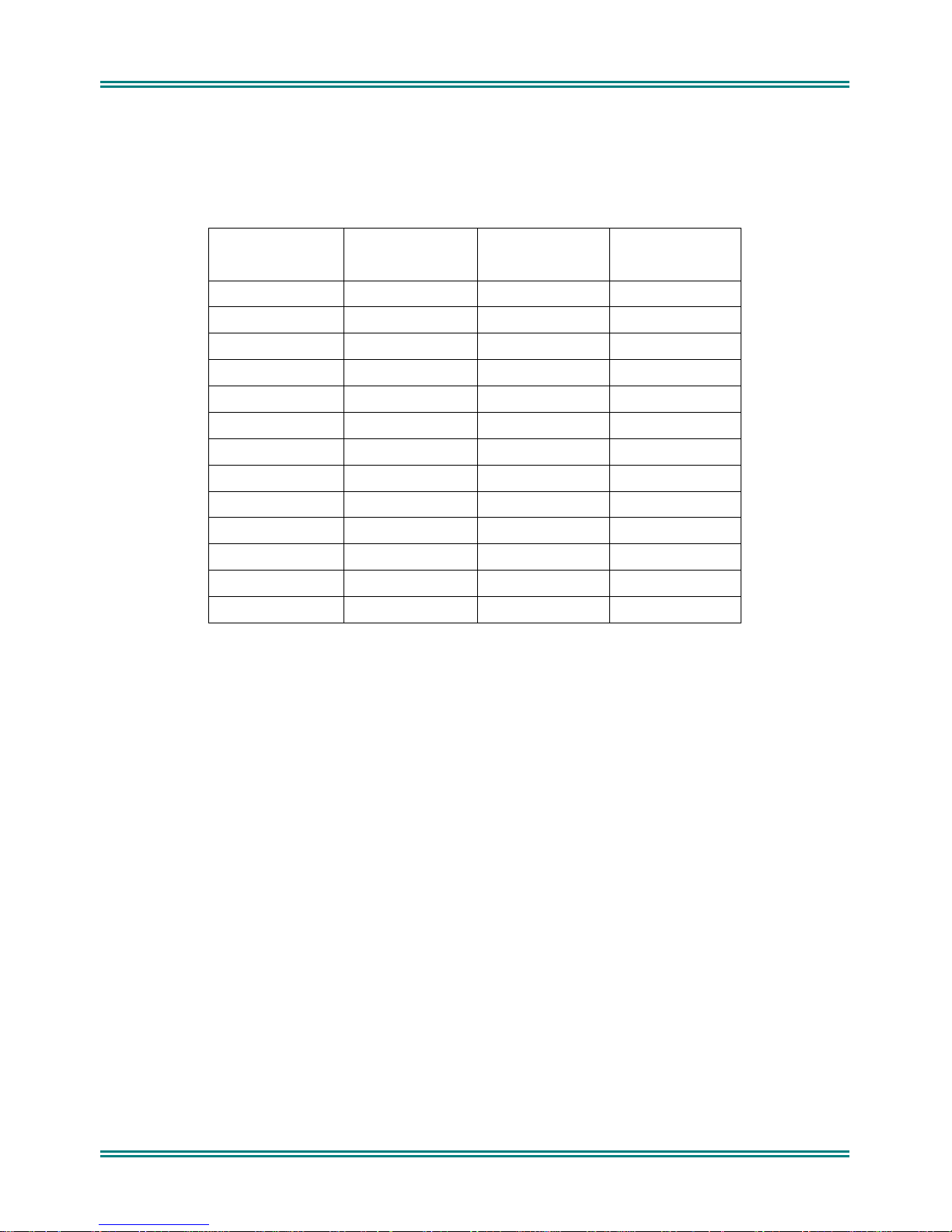
Document History
Issue Date Comments
1 January 2008 Initial issue
List of Associated Publications
Document No. Description Issue
TNM-I-E-0005 SRM9000 Series Installation Instructions 6
TNM-P-E-004 Selcall Product Manual 2.56
TNM-U-E-0055 SRM9022 P25 Operating Instructions 2
TNM-U-E-0074 SRM9030 P25 Operating Instructions 2
© TMC Radio 2008 page v TNM-M-E-0 02 2 Issue 1

SRM9000X8 800MHz SERVICE MANUAL
Warnings and Cautions
Compliance with RF Energy Exposure Standards: To minimise exposure to RF fields during
equipment service and repair, the antenna terminal of the SRM9000 radio should be connected to
a suitable non-radiating RF load when the transmitter is in use.
SRM9000 radio equipment is to be connected
with a 24-volt supply, an approved 24V/12V converter must be used. The supply must not be
taken from a 12V tap on the battery.
To avoid RF injury, do not touch the Antenna when the Transmitter is in use.
Double-fused 12V Supply Leads, Antenna cables and Speaker wiring is to be routed as far away
as possible from gas or fuel lines or any electronic control device. The radio transceiver and
antenna are to be mounted as far away as possible from these devices and their cabling.
Equipment is to be installed, by a competent person, in accordance with the requirements of
local radio communications authorities and/or Health and Safety regulations.
Post installation checks should be performed to ensure that there is no effect on the operation of
the vehicle’s electronics.
WARNING
WARNING
only
to 12-volt negative earth systems. In vehicles
WARNING
WARNING
WARNING
Do not operate your radio, without a handsfree kit, whilst driving a vehicle.
WARNING
Do not operate your radio in an explosive atmosphere. Obey the “Turn Off Two-way Radios”
signs where these are posted, e.g. on a petrol station forecourt.
Caution
During disassembly and assembly, refer to Torque Settings in Section 1.6
Caution
Customer configuration files should be saved prior to any alignment adjustments.
Preparing the radio for alignment will erase from the radio all customer PMR configuration data
(channel, signalling information etc). The only data retained by the Alignment Tool is the factory
alignment data for the radio (DAC settings for Tx power, front-end tuning etc).
© TMC Radio 2008 page vi TNM-M-E-0022 Issue 1

SRM9000X8 800MHz SERVICE MANUAL
1. INTRODUCTION
1.1 GENERAL
The SRM9000X8 800MHz mobile transceiver is designed for PMR operation in analog systems or P25 in digital
systems.
The SRM9000X8 transceiver can be used with either the SRM9022 Graphics Display Handset or the SRM9030
System Level Remote Control Head with Alpha capability.
1.2 S
This manual provides technical specifications, description and servicing details for the SRM9000 mobile radio
transceiver.
COPE
1.3 DESCRIPTION
The design concept utilises wide band techniq ue s fo r RF tr ansmit and receive circuitry with digital signal
processing of analog or digital modulatio n a nd dem od ula tion. Electronic tuning is used throughout the mobile to
eliminate manual tuning and level adjust ment.
A Digital Signal Processor (DSP) and a Programmable Gate Array (PLA) are used with other dedicated dev ices in
the SRM9000 to perform the following fu nctions under software control:
• Frequency Synthesis of all operating frequencies.
• Modulation and demodulation of 12 . 5kHz o r 25 kHz FM signals or P25 digital modulation on a per
channel basis.
• Modem functionality for specified d ata modulation schemes.
• Filtering, pre-emphasis, de-emphasis, limi ting, compression, muting, CTCSS, Selcall or any other
frequency or level dependent signal modification.
• Serial communications with the Control Ancillaries and Alignment Tool.
Tuning Control data for Tx and Rx.
•
The SRM9000 basic Transceiver comprises a rugged extruded aluminium sleeve, which houses a single printed
circuit board assembly and provides all heatsink requirements. The sleeve housing is closed at each end by highimpact plastic end caps; all cable ports and mechanical interfaces are sealed against moisture and dust ingress.
The PCB assembly comprises a single, multi-layer PCB cont ain i ng all the RF and control circuitry. The PCB seats
on an extruded aluminium tray that slides into the outer aluminium sleeve where it is secured with screws
accessed from the outside of the case. Provision is made under the main PCB tray assembly for additional
hardware options as well as optional a ccessor ies p l ug ged directly into the main PCB.
There are two installation methods available for the SRM9000. The outer aluminium extrusion has side flanges that
allow the mobile to be bolted directly to any flat surface in the vehicle. A quick release cradle is also available.
© TMC Radio 2008 pag e 1 TNM-M-E-0022 Issue 1

SRM9000X8 800MHz SERVICE MANUAL
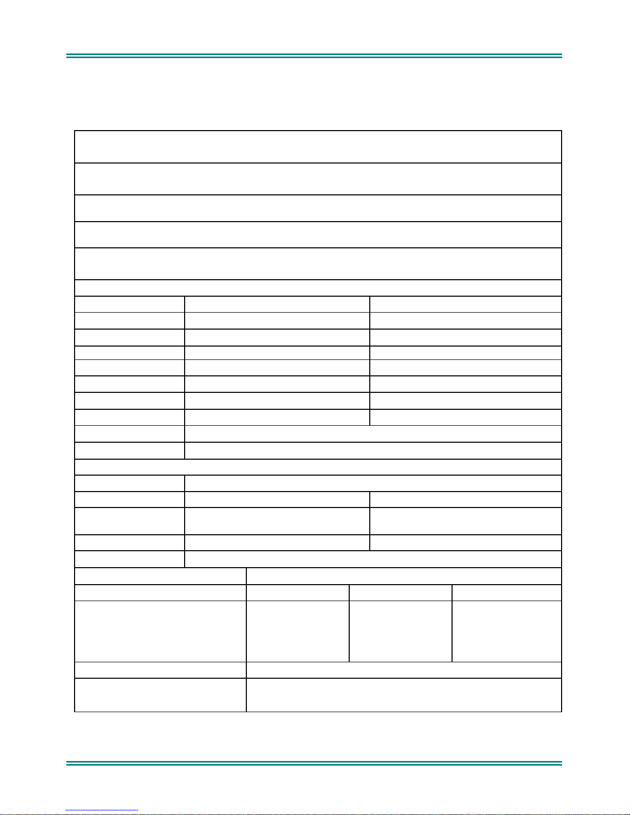
1.4 PRODUCT VARIANTS AND FACILITIES
Product variants and facilities are detailed in Tables 1-1, 1-2 and 1-3.
Table 1-1 Features for Control Variants
Feature: Model: 9022 9030
Control
Display
Controller
Microphone
8x14 char LCD
Graphics 102x64
pixels
Control Unit with
Microphone
8x14 char LCD
Graphics 102x64
pixels
Adjustable Display
Yes Yes
Illumination
Buttons and Keys
Speaker
Channel Spacing
Menu driven
Customisable Menus
Vol Up/Down
6 Function
12 Keypad
Send/End
Menu + Scroll
Yes Yes
12.5kHz/ 25kHz
Yes Yes
Yes Yes
6 Function
12 Keypad
Send/End
Menu + Scroll
© TMC Radio 2008 pag e 2 TNM-M-E-0022 Issue 1

SRM9000X8 800MHz SERVICE MANUAL
Table 1-2 Conventional-PMR Vari a n ts
Feature: Model: 9022 9030
Channels
Signalling
Attack Operation
DTMF Encode
PTT Limit Timer with
warning beeps
Busy Channel Lockout
PTT Inhibit on Busy
Scanning
Voting
Priority Scanning
Nuisance Delete
Phonebook
Multiax
Ignition Sense Input
VOX Handsfree
600 Ohm Interface
SIB
ASIG
P25
124 groups of up to 16 channels per group, 4 user defined
Up to 200 groups consisting of up to 16 channels per
1000 1000
CTCSS/DCS
Selcall
Yes Yes
Yes Yes
Yes Yes
Yes Yes
Yes Yes
scan groups.
group.
Yes Yes
Yes Yes
250 entries 250 entries
Yes Yes
Yes Yes
Yes Option
Option
Option
Option
Option
CTCSS/DCS
Selcall
© TMC Radio 2008 pag e 3 TNM-M-E-0022 Issue 1

SRM9000X8 800MHz SERVICE MANUAL
Software Versions and Naming
There are various associated items of Software (SW) required for the SRM9000 radio and programmer to operate.
This section simply defines the naming rules of the SW files to allow identification and conformity. This allows
different versions of SW to be distributed and co-exist without confusion.
The SRM9000 Transceiver has three items of SW fo r digital and analog PMR, Trunking and Alignment.
The 9022 Controller Mic/Handsets has one SW file for its PIC and the 9030 Control Head has two SW files for its
Flash and EEPROM.
1.4.1
Basically the Filename Structure is defined as follows:
• 2 character Applicatio n cod e
• 2 or 3 character SW Type code
• 3 character version number
• File Extension as required.
eg.
9ep_533.bin
9es_533.bin
9ecf101.hex
9ece101.hex
1.4.2
This identifies the application the SW was initially des i gned for:
9e Standard SRM9000 Rev 9 Software
ae SRM9000 Rev 9 Softwar e ap plicable for SRP9022
Filename Structure
9etm533.bin
Application Code
1.4.3
This identifies different types of SW within an application.
a_a 9022 PMR with ASI Map27option board
a_u 9022 PMR with ASI SUP option board
Software Type Code
s_ Startup
p_ Standard PMR. DMAP or No option board
p_s PMR with Scrambler/Discriminator option bo ard
p_g PMR with Direct GPS
p_a PMR with ASI Map27option board
p_u PMR with ASI SUP option board
p_q PMR with ASI-G Map27option board
a__ 9022 Standard PMR. DMAP or No option board
a_s 9022 PMR with Scrambler/Discriminator op tion board
a_g 9022 PMR with Direct GPS
© TMC Radio 2008 pag e 4 TNM-M-E-0022 Issue 1

SRM9000X8 800MHz SERVICE MANUAL
a_q 9022 PMR with ASI-G Map27option board
bo Transceiver Boot-code
bc Transceiver Boot-Backup-code
bf Transceiver PLA-code
ba Transceiver PLA-Backup-code
Note. The above file names are not store d within the code. As a consequence, when the radio is read by the FPP,
the FPP will display version numbers and release dat e s f o r th e Backup, Startup, PMR and DMAP codes. The
Bootloader, PLA Backup and PLA codes show release dates only.
© TMC Radio 2008 pag e 5 TNM-M-E-0022 Issue 1
SRM9000X8 800MHz SERVICE MANUAL
1.4.4
This is a 3-digit number allocated by Engineering to identify the SW version.
e.g. 103 = Version 1.03
1.4.5
The Programmer SW does not follow the above ru les as it is a PC based Program and its version number can be
easily identified by starting th e SW . Later releases of SW will be backward compatible, unless deliberately not so,
in which case a different directory structure/path may be implemented.
1.4.6
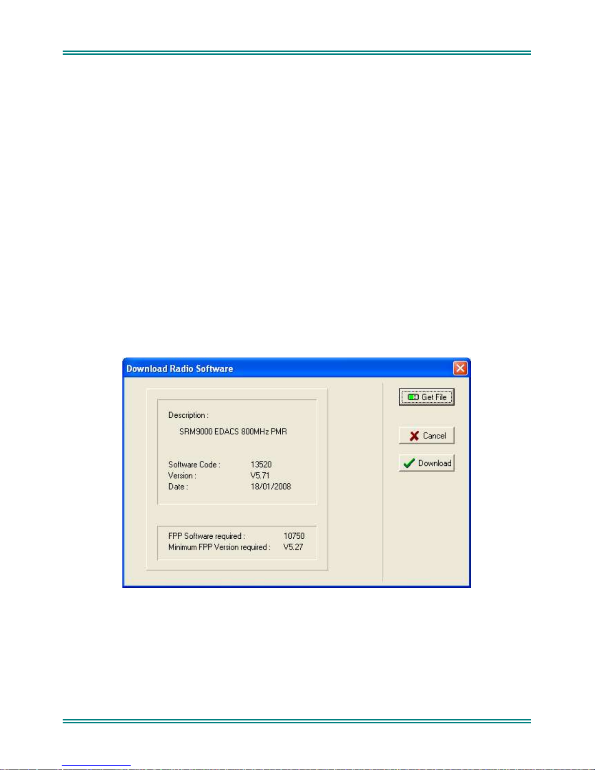
Each Transceiver SW code file (e.g. 9etm533.bin, etc.) contains version information about itself and possible
compatibility with Programming SW.
For
Version Number
Exclusions
Displaying Software Versions
Radio SW saved on Disk
Options : Upgrade_Software : Get_File
, this information can be displayed via the Programmer function:
© TMC Radio 2008 pag e 6 TNM-M-E-0022 Issue 1
SRM9000X8 800MHz SERVICE MANUAL
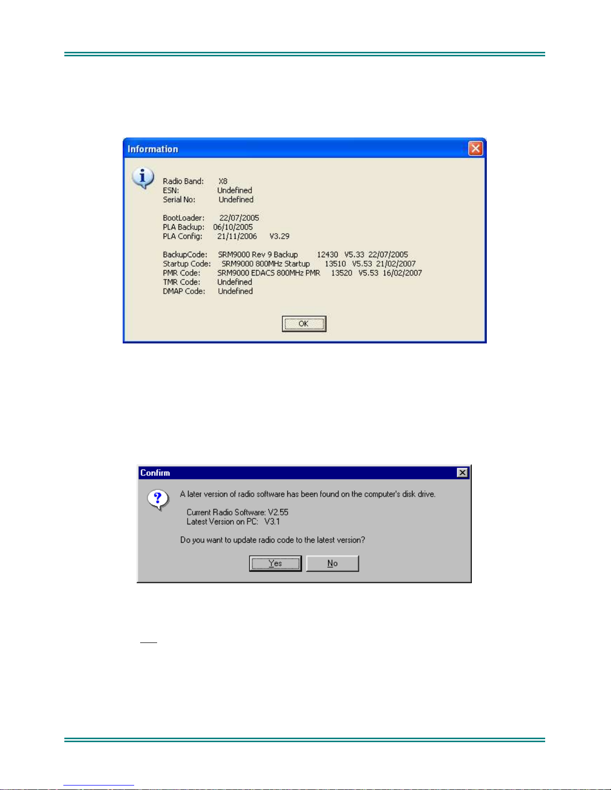
For
Software loaded in the radio
Programmer function:
SRM9030 Control Head SW
is switched on.
switched on.
Options : Radio_Information
SRM9022 Handset SW
, information can be read from the Transce iver and displayed via the
can be displayed on the Control Head by holding the ‘3’ button down when the radio
can be displayed by pressing the top side button when the radio is
1.4.7
When a configuration is downloaded to the Transceiver, the Programmer performs a brief check on the SW
currently installed in the radio. If a later version of SW exists (on PC hard-disk) then the Programmer will prompt
the user with the following message :
NOTE. As early versions of FPP cannot recognise a more recent revision of the radio, it is important that the latest
FPP version is downloaded from http://www.tmcradio.com.
If
YES
If NO is selected, only
This process also updates the Startup code to ensure it is compatible with the loaded PMR code.
Note : If the …\SRM9000\FPP\Radi oSW folder contains no files, then the above check will not be perform ed .
Automatic Version Upgrade Prompting
is selected, the Transceiver Radio code is updated before the new configuration is downloaded.
the configuration is downloaded.
© TMC Radio 2008 pag e 7 TNM-M-E-0022 Issue 1

SRM9000X8 800MHz SERVICE MANUAL
1.4.8
The SRM9000 Transceiver software is split into th e following separate modules:
When the Transceiver starts, it basically performs the following steps:
If the Mainline Software cannot be lo ad ed, or a Job file configuration has not been loaded (e.g. non-existent or
checksum fail) then execution switche s to Backup Software until the error is corrected (e.g. by FPPing the radio).
There are three states that the radio can configure after switch-on:
Transceiver SW Description, Start-up and Backup-Software
• Bootloader and Backu p Software
• Start-Up Soft war e
• PLA and PLA-Backup Software
• Mainline PMR Software
• Initial execution starts with the Bootloader code, which attempts to load the Start-Up Software (if Start-
Up checksum is bad, then the Backup Software is lo ad ed .)
• Start-Up Software then do wnloads the PLA code (or PLA-Backup code if PLA checksum is bad) to the
PLA device. If both PLA and PLA-Backup checksu ms are ba d then the radio is not operational and serial
communication is not possible.
• Start-Up Soft war e then reads the On/Off switch plus Ignition-Sense lines and compares t he se with
saved parameters to determine if the rad i o sho uld be continue to power-up or switch itself off again.
• Start-Up software t h en attempts to load PMR Mainline Software (dependent on save d pa ra meter) and
switches execution to complete the powe r-up process and start normal operation.
• Mainline PMR Softw are (no rma l po wer-up)
If the radio does not have a vali d Jo b file configuration loaded, then it will display a “No PMR Cfg”.
• Start-Up Software (characterised by “Alignment Mode” shown on the display). This is also t he cod e that
is running when the radio is being aligned using the Alignment Tool.
• Backup Software (via various paths from above.)
1.4.9
A “WAILING SIREN” sound is emitte d from the Loudspeaker while the radio is running in Boot Backup Softw are .
In this mode the FPP can be used to re-load a Jo bf ile, or re-load Start-Up or Mainline Operating Software.
Simply writing a Jobfile to the radio should allow the FPP to determine and update the offending software –
however there may be instances where the FPP cannot determine this and the Start-Up and Mainline Software
should be updated manually. This can be do ne using the FPP : Upgrade_Software : Get_File … then Download.
Both Start-Up Software (filename = 9es_xxx.bin) and Mainline PMR (9ep_xxx.bin) should be loaded if the FPP
cannot automatically fix the problem. The wailing siren s hould stop once the problem is fixed.
Note: Should these steps fail to restore the set and the Wailing Siren cease, the radio will need to be returned to
Wailing Siren (Boot-up Software Corrupted)
a Level 3 Service Centre for FLASH repl ace ment.
1.5 ADJUSTMENT AND ALIGNMENT
There are no manual internal adjustments in the SRM9000. Re-programming and alignment is done using
software tools with the PCB installed in its chassis. For servicing, the radio PCB can be operated outside the
chassis provided that a temporary heatsink is fitted under the transmitter PA module for transmitter servicing and
that the receiver audio output be kept below 100mW for receiver servicing. Radio performance is only slightly
affected by operating without the outer sleeve but there will be some change to performance when the metal cans
are removed from the RF sections of the board.
On re-assembly, the PA module should be checked for a thin layer of heat-conducting paste. If this is missing or
dried-out, it should be replaced prior to re-assembly.
© TMC Radio 2008 pag e 8 TNM-M-E-0022 Issue 1

SRM9000X8 800MHz SERVICE MANUAL
1.6 C
HASSIS ASSEMBLY
Important Note!
1.6.1
Assembly of 'Chassis' (Inner Extrusion) to 'Outer Extrusion': 1.4 Nm (PA x 2), 1.25Nm (Others x 3)
Assembly of 'Front' and 'Rear' end-caps to 'Outer Extrusion': 1.4 Nm.
1.6.2
Just enough thermal compound should be applied to the PA tray to provide good thermal contact with the chassis.
Note. If thermal compound is old and difficult to spread, it should be discarded.
1.6.3
The Inner extrusion should initially be ne ste d t og et h er with the PCB and then the assembly slid into place within
the outer extrusion.
Positioning the inner extrusion upwards by hand, it is then important to insert all screws by hand and ensure they
have been fully inserted through the PCB, thereby locating the assembly correctly.
Whilst holding the inner extrusion upwards to ensure the assembly does not twist, lightly torque up the centre
screw of the row of three followed by the PA module mounting screw towards the middle of the chassis.
The remaining screws can then be screwed up to full torque followed by re-torque of the first two screws.
Torque Settings
Thermal Compound Application
Assembly
© TMC Radio 2008 pag e 9 TNM-M-E-0022 Issue 1
SRM9000X8 800MHz SERVICE MANUAL
1.7 S
1.7.1
Operation
Single frequency simplex or two-frequency simplex (half-duplex).
Modulation
Frequency modulation (phase) F3E and F1 E.
Operational Temperature Range
-30°C to +60°C
Storage Temperature Range
-40°C to +80°C
Supply Voltage Requirements
10.8V to 16.32V DC negative earth (13.8V nom.)
Current Consumption
Radio off
Standby (squelched):
Rx Audio O/P:
Transmit:
Frequency Band Frequency Range
Channel Spacing
Frequency Stability (-30°C to 60°C)
Dimensions
* Does not include cable or strain relief
Weight
PECIFICATION
General
300mW
4.0W
25W
6W
*Add 100mA to current consumption for the 9030 Control Head with backlight on.
X8 Transmit Receiver
2 Frequency
Simplex
Turnaround 851-870MHz 851-870MHz
(mm)
9022 Controller Microphone
9030 Alpha Control Head
Mobile With 9022 Control Mic Mobile With 9030 Alpha Head
≤ 5mA ≤ 5mA
≤ 200mA ≤ 210mA*
≤ 450mA ≤ 500mA *
≤ 1200mA ≤ 1250mA*
Transceiver
Transceiver
806-825MHz 851-870MHz
12.5kHz/ 25kHz
Height Width Depth
56
145*
300
1.8kg
≤ 7.0A
≤ 3.0A
Less than ±1.5ppm
170
68
120
165
30
130
© TMC Radio 2008 page 10 TNM-M-E-0022 Issue 1

SRM9000X8 800MHz SERVICE MANUAL
Regulatory Approvals
1.7.2
Transmitter
Power Output
Carrier Attack Time
Duty Cycle
Spurious Emissions
FM Hum & Noise
Audio Frequency Distortion
Audio Frequency Response
Audio Sensitivity (1kHz)
(User programmable via FPP)
FCC ID: STZSRM9000X8
IC: 7068A-M9000X8
Any two levels are programmable:
High Power: 25W Adjustable down to 1W
Low Power: 1W Adjustable up to 25W
Less than 50 ms
1 minute transmit: 4 minutes receive
< -20dBm
25kHz Channel Spacing: >40dB
< 5%.
300 to 3000Hz +1dB to -3dB of a 6dB/octave pre-
emphasis curve.
RJ8 Connector: 40mV±2dB from 470
Option Audio: 40mV±2dB.
source impedance.
Ω
© TMC Radio 2008 page 11 TNM-M-E-0022 Issue 1

SRM9000X8 800MHz SERVICE MANUAL
1.7.3
Sensitivity
Adjacent Channel Rejection
Offset Channel Rejection (NPSPAC)
Intermodulation Rejection
Spurious Response Rejection
Blocking
Conducted Spurious Emissions
FM Hum & Noise (
Mute Range
Receiver
Analog 25kHz
Analog 25kHz)
Analog
C4FM
C4FM
< -117.5dBm for 12dB SINAD
< -116dBm for 5% BER
>70dB
>60dB
>20dB
>70dB
>70dB
>90dB
<-57dBm
>40dB
Typically 6dB to 25dB SINAD
Typical preset level 10dB ±2dB SINA D
Receiver Attack Time
Receiver Closing Time
Audio Distortion
Audio Frequency Response
Deviation Sensitivity
(for rated audio at 1kHz)
<150mS
<90mS
4W into 4Ω at <5% distortion
300 to 3000Hz: +2dB to -8dB of a 6dB/octave de-emphasis
curve
20% to 40% PSD
© TMC Radio 2008 page 12 TNM-M-E-0022 Issue 1
SRM9000X8 800MHz SERVICE MANUAL
1.7.4
1.7.4.1 CTCSS
38 standard CTCSS Tones and 13 non-standard tones are supported as per the table below:
CTCSS Encoder
Tone Deviation:
25kHz channel spacing: 500 to 750Hz
NPSPAC: 400 to 600Hz
Tone Distortion: Less than 5.0%
Tone Frequency Error: Less than ±0.3%
Signalling
Frequencies
Standard
67.0 107.2 167.9 69.3
71.9 110.9 173.8 150.0
74.4 114.8 179.9 159.8
77.0 118.8 186.2 165.5
79.7 123.0 192.8 171.3
82.5 127.3 203.5 177.3
85.4 131.8 210.7 183.5
88.5 136.5 218.1 189.9
91.5 141.3 225.7 196.6
94.8 146.2 233.6 199.5
97.4 151.4 241.8 206.5
100 156.7 250.3 229.1
103.5 162.2 254.1
Standard
Frequencies
Standard
Frequencies
Non-Standard
Frequencies
© TMC Radio 2008 page 13 TNM-M-E-0022 Issue 1

SRM9000X8 800MHz SERVICE MANUAL
CTCSS Decoder
Bandwidth Complies wit h TI A- 603 part 3.4.6
Deviation Sensitivity Less than 6.0% of system deviat io n (for decode with full RF quieting)
Noise Immunity Less than 50 0ms dr op out per minute at 10dB SINAD
(CTCSS tone deviation 10% of system deviation. RF deviation 60% at 1000Hz).
False Decode Rate Less than 1 false decode pe r 30 m inutes (no carrier input).
Blocking For no dropouts in one minute, interfering tone at 90% of system deviation
(CTCSS tone at 10% of system dev iation) as follows:
Full quieting signal: 310Hz to 3000Hz
20dB SINAD RF signal: 320Hz to 3000Hz
12dB SINAD RF signal: 350Hz to 3000Hz
Attack Time Less than 25 0ms (tone frequency >100Hz)
Less than 350ms (tone frequency <100Hz)
Closing Time Less than 250ms
Squelch Tail Elimination Less than 50ms
1.7.4.2 Selcall
The following tone sets are supported as per tables below:
ST-500: CCIR, EEA, ZVEI, DZVEI, EIA
•
• ST500/CML: ZVEI_3, DZVEI
• CML: CCIR, EEA, ZVEI
• SIGTEC: CCIR, CCIRH, EEA, ZVEI_1, XVEI_2, ZVEI_3, NATEL, EI A
• SEPAC: CCIR, EEA, ZVEI_1, ZVEI_2, ZVEI_3, EIA
© TMC Radio 2008 page 14 TNM-M-E-0022 Issue 1

SRM9000X8 800MHz SERVICE MANUAL
Selcall Tone Frequency Table
Tone CML ST500 SIGTEC SIGTEC SEPAC CML ST500 SIGTEC
CCIR CCIR CCIR CCIRH CCIR EEA EEA EEA
0 1981 1981 1981 1981 1981 1981 1981 1981
1 1124 1124 1124 1124 1124 1124 1124 1124
2 1197 1197 1197 1197 1197 1197 1197 1197
3 1275 1275 1275 1275 1275 1275 1275 1275
4 1358 1358 1358 1358 1358 1358 1358 1358
5 1446 1446 1446 1446 1446 1446 1446 1446
6 1540 1540 1540 1540 1540 1540 1540 1540
7 1640 1640 1640 1640 1640 1640 1640 1640
8 1747 1747 1747 1747 1747 1747 1747 1747
9 1860 1860 1860 1860 1860 1860 1860 1860
A 2400 1055 2110 2400 2400 1055 1055 2110
B 930 .... 2400 930 1055 930 .... 1055
C 2247 2400 1055 2247 2247 2247 2400 2400
D 991 .... 2247 991 991 991 .... 2247
E 2110 2110 930 2110 2110 2110 2110 930
F .... .... 991 1055 .... .... .... 991
Tone SEPAC CML ST500 SIGTEC SEPAC SIGTEC SEPAC SIGTEC
EEA ZVEI ZVEI ZVEI-1 ZVEI-1 ZVEI-2 ZVEI-2 ZVEI-3
0 1981 2400 2400 2400 2400 2400 2400 2200
1 1124 1060 1060 1060 1060 1060 1060 970
2 1197 1160 1160 1160 1160 1160 1160 1060
3 1275 1270 1270 1270 1270 1270 1270 1160
4 1358 1400 1400 1400 1400 1400 1400 1270
5 1446 1530 1446 1446 1446 1446 1446 1400
6 1540 1670 1670 1670 1670 1670 1670 1530
7 1640 1830 1830 1830 1830 1830 1830 1670
8 1747 2000 2000 2000 2000 2000 2000 1830
9 1860 2200 2200 2200 2200 2200 2200 2000
A 1055 2800 970 2600 2800 970 885 2400
B 970 810 .... 2800 970 885 741 885
C 2247 970 2800 741 885 741 2600 741
D 2400 886 .... 970 .... 2600 .... 2600
E 2110 2600 2600 810 2600 2800 970 2800
F .... .... .... 886 .... 600 .... 600
© TMC Radio 2008 page 15 TNM-M-E-0022 Issue 1

SRM9000X8 800MHz SERVICE MANUAL
Tone SEPAC ST500/CML ST500 SIGTEC SIGTEC SEPAC ST500
ZVEI-3 ZVEI-3 DZVEI DZVEI NATEL EIA EIA EIA
0 2200 2400 2200 2200 1633 600 600 600
1 970 1060 970 970 631 741 741 741
2 1060 1160 1060 1060 697 882 882 882
3 1160 1270 1160 1160 770 1023 1023 1023
4 1270 1400 1270 1270 852 1164 1164 1164
5 1400 1530 1400 1400 941 1305 1305 1305
6 1530 1670 1530 1530 1040 1446 1446 1446
7 1670 1830 1670 1670 1209 1587 1587 1587
8 1830 2000 1830 1830 1336 1728 1728 1728
9 2000 2200 2000 2000 1477 1869 1869 1869
A 885 885 2600 825 1805 459 2151 2151
B 741 .... .... .... 1995 2151 1091 ....
C 2600 810 886 2600 1300 2600 2400 2010
D .... .... 810 .... 1700 2010 .... ....
E 2400 970 2400 2400 2175 2433 459 459
F .... .... .... .... 2937 2292 .... ....
Selcall Tone Periods
4 preset lengths selectable: 20ms to 4 secon ds in 1 ms increme nts.
1.7.4.3 DTMF
DTMF Encode supported via keypad:
TONES 1209Hz 1336Hz 1477Hz
697Hz 1 2 3
770Hz 4 5 6
852Hz 7 8 9
941Hz * 0 #
Tone Period, programmable: 0 – 2.55s in 10ms steps.
Inter-Tone Period, programmable: 0 – 2.55s in 10ms steps.
Link Establishment Time, programmable: 0 - 10s in 10 ms steps.
Tx Hang Time, programmable: 0 – 9.99s in 10ms steps.
Side-Tone in Loudspeaker: selectable vi a pr og ra mme r
© TMC Radio 2008 page 16 TNM-M-E-0022 Issue 1
 Loading...