

TMC Radio SRM9000 SERIES Installation Instructions Manual
SRM9000 SERIES
SPEAKER INSTALLATION
The Speaker is to be located so that vehicle structure will not cause muffling or distortion o
f
the audio signal. Suggested locations include the console, under the dashboard, or on the
rear parcel shelf.
The Speaker cable can either be connected to the Transceiver LT Lead directly, or via the
Speaker Extension Lead.
Note: Connectors are polarised to ensure that the correct speaker polarity is maintained.
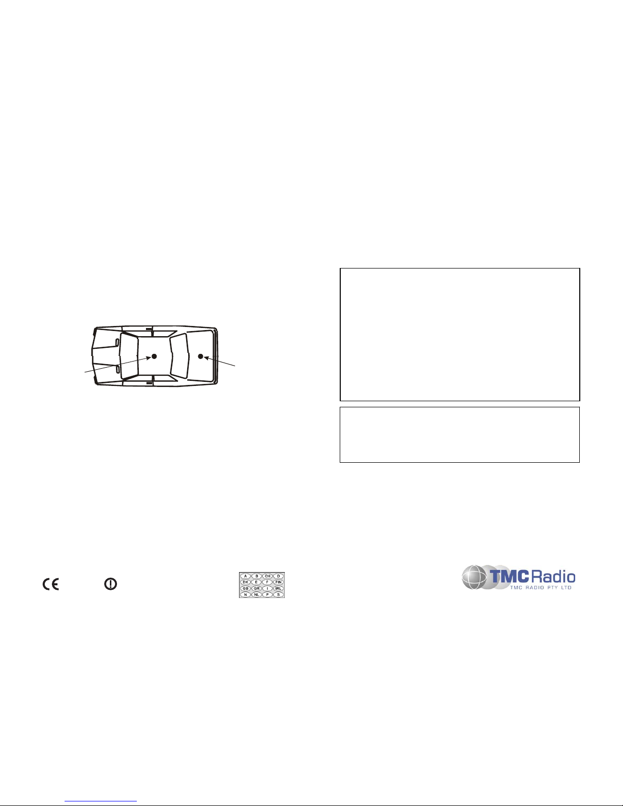
ANTENNA INSTALLATION
For optimum radio performance it is recommended that the Antenna be mounted in the
centre of the vehicle roof. If the Antenna is to be fitted to a fibreglass, or other non-metallic
surface that does not have a sizeable groundplane (~ ½ wavelength diameter), then a
ground-plane-independent Antenna must be used.
Boot Mount
Roof Mount
Typical Antenna Locations
Route the coaxial cable to the Transceiver and install the Antenna according to the
manufacturers instructions
Terminate the coaxial cable using a BNC connector. Ensure that all of the vehicle doors
are closed and using a Reflectometer between the Transceiver and the Antenna BNC,
conduct a VSWR check. If the VSWR is >1.5:1, re-check the Antenna and
cabling/connections. If the VSWR <1.5:1, connect the Antenna BNC to the Transceive
r
A
ntenna socket.
POST INSTALLATION CHECKS
When performing RF compatibility checks, ensure that the Transmitter is activated only fo
r
the time required to make the observation.
With the vehicle stationary and the engine running at fast idle, activate the Transmitter and
check that the engine continues to run smoothly, the brake lights do not illuminate, and that
all dashboard instrumentation indicates correctly.
• Operate the brake pedal, activate the Transmitter and ensure that the brake lights do
not extinguish.
• Operate the direction indicators, activate the transmitter and ensure that indicators
operate correctly.
• Put the vehicle into motion at a moderate speed (15-20 kph or 10-13 mph), activate the
Transmitter, and operate the brake pedal simultaneously. Check that braking action is
normal, and that the engine does not surge or cut out.
INSTALLATION INSTRUCTIONS
WARNINGS and CAUTIONS
SRM9000 radio equipment is to be connected only to 12-volt negative earth
systems.
In vehicles with a 24-volt supply, an approved 24V/12V converter must be used.
The supply must not be taken from a 12V tap on the battery.
Equipment is to be installed in accordance with the requirements of local radio
communications authorities and/or Health and Safety regulations.
12V Supply Leads, Antenna cables and Speaker wiring is to be routed as far
away as possible from gas or fuel lines. This reduces the risk to safety in the
event of a leak.
In vehicles fitted with Electronic Ignition, Fuel injection, Anti-skid brakes, or any
other electronic control device where temporary loss of service could be
hazardous, the radio transceiver and antenna are to be mounted as far away as
possible from these devices and their cabling.
To avoid RF injury, do not touch the Antenna when the Transmitter is in use.
POLICY STATEMENT
Due to our policy of continuous improvement of our products and services, technical
specifications, correct at time of publication, may be subject to variation without prio
r
notice. TMC Radio has endeavoured to ensure that the information in this document is
fairly stated, but does not accept liability for any errors or omissions. This publication is
copyright and no part may be reproduced without prior permission of TMC Radio.
INTRODUCTION
These instructions are intended as a guide for installation. Please contact your supplier fo
r
any additional advice that may be required.
These instructions are to be read with reference to the Installation Diagram supplied. Text
in this document in Italics refers to items on the Installation Diagram.
Be aware of the hazards provided by joint presence of fuel (petrol or gas) and sparks.
Post installation checks should be performed to ensure that there is no effect on electronic
management systems.
TNM-I-E-0005 Issue 5
ABCDE
Hereby, TMC Radio declares that this
product is in compliance with the essential
requirements and other relevant provisions
of Directive 1999/5/EC.
0885
©
TMC 2004
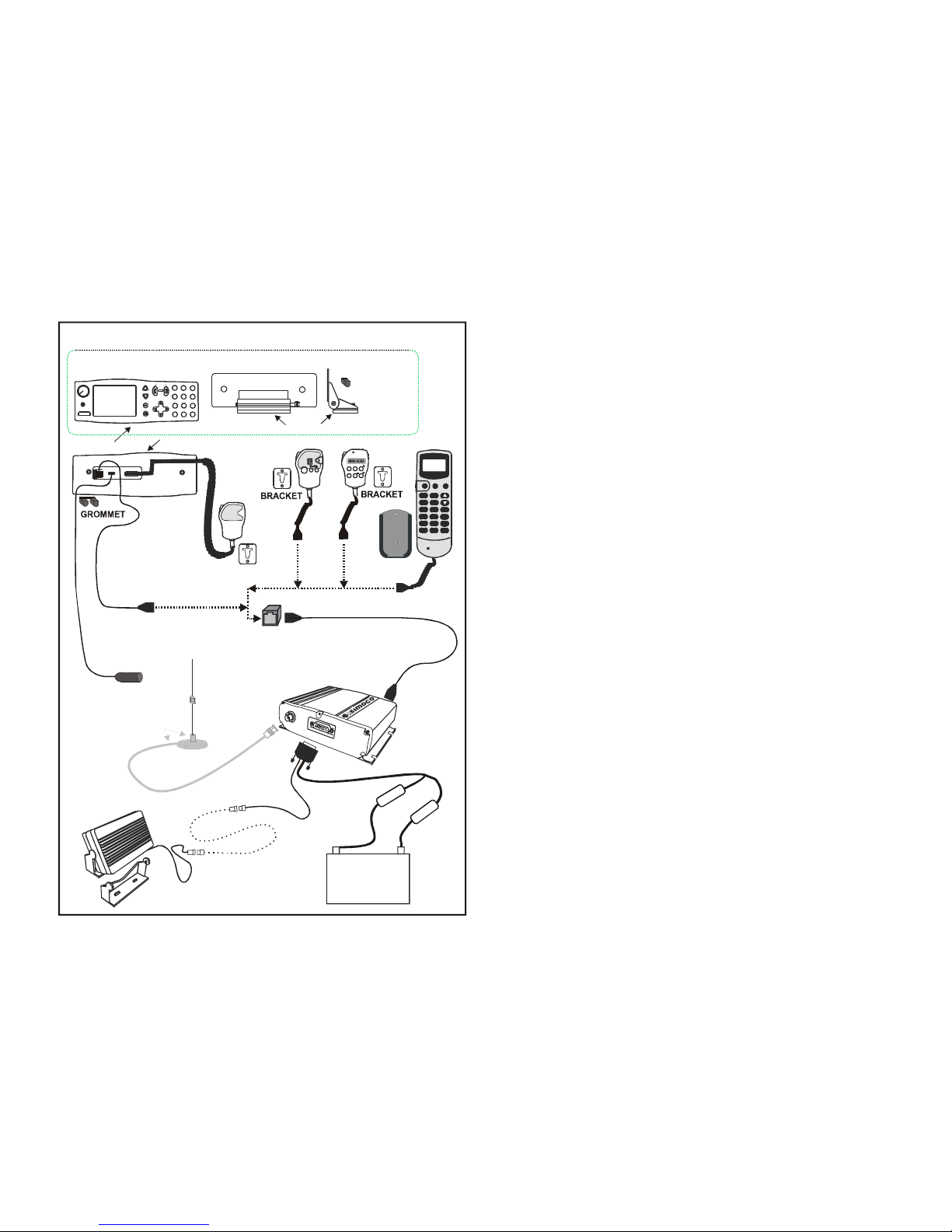
OPTIONAL
JUNCTION
BOX
ANTENNA
CABLE
ANTENNA
Items not supplied
with SRM9000.
SPEAKER
EXTENSION
CABLE
MAJORITY
RED
CABLE
12V
VEHICLE
BATTERY
+
-ve
MAJORITY
BLACK
CABLE
SPEAKER
&
CRADLE
OPTIONAL
MICROPHONE/CONTROL HEAD
EXTENSION CABLE
(3502 310 63 290)
LT CABLE
FUSES
TRANSCEIVER
OPTIONAL
HANDSFREE
MICROPHONE
AND CLIPS
Select
On/Off
F6
F1 F2
F5
F4
F3
x
M
S
SRM9010
SRM9020
BRACKET
SRM9025
PWRSNDEND
M
H
*
O
#
98
7
4
56
12
3
CLR
SEL
ABCQZDEF
GHI
JKL
MNO
PRS
TUV
W
XY
OPER
SRM9030
X
2 GROMMET
MICROPHONE
& BRACKET
or HANDSET
CONTROL
CABLE
(FRONT) (REAR)
1
23
4
56
78
9
*
0#
ABC DEF
GHI JKL MNO
PQRS
TUV
WXYZ
...
.
BASE
PLATE
CONTROL HEAD BRACKET
(FRONT) (SIDE)
TRANSCEIVER INSTALLATION
The Transceiver is designed to be mounted in the luggage compartment or under the front
seat. Do not cover the transceiver with carpet, mats or luggage.
Locate the Transceiver in the desired position. A minimum clearance of 20mm around the
Transceiver is recommended to ensure adequate airflow.
Secure the Transceiver in position using the supplied screws. Alternatively, if the Quick
Release Mounting option is used, mount the Cradle in the desired position and clip the
transceiver into the Cradle.
POWER & OPTION CABLING
Run the LT-Cable from the installed Transceiver to the Vehicle Battery terminals. Ensure
the cable is routed with enough slack so that it is not under tension in its travel. Allow an
extra 0.5m before cutting off excess. Ensure any holes that the cable passes through are
de-burred and fitted with a grommet.
Fit the Fuses in both +VE and -VE wires of the cable pair. The Fuses are to be fitted within
approximately 0.5m of the Battery before the cable has contact with other cables or the
vehicle body. Only 12V, 10Amp, fast blow fuses should be used.
On the DB15 Power/Speaker connector, connect Pins 3 and 14 as follows:
Pin 3 (Ignition Sense) Connect Pin 3 to the Ignition Switch wiring such
that +12V is applied when the ignition is switched
ON and is disconnected when the ignition is
switched OFF.
Pin 14 (Handsfree Mic) Refer to separate Installation Instructions for
connection of the Handsfree Microphone.
CONTROL HEAD/HANDSET/MICROPHONE INSTALLATION
The Control Head and/or Microphone/Handset stowage bracket should be mounted so that
the display and control buttons are readily visible and accessible to the driver when
constrained by a seatbelt. Ensure that these locations are chosen such that the equipment
cannot cause injury in the event of an accident. Ensure that all in-cab equipment is mounted
outside the passenger’s safety zone. Ensure that there is adequate room for cables to exit
the Control Head without interference.
Do not locate the Control Head/Handset/Microphone on the top of the dashboard or in direct
sunlight as the temperature of exposed surfaces may rise over 100°C in the sun.
Locate the Handset/Microphone Bracket where the driver can readily remove or stow the
Handset/Microphone. Ensure that the curly cord is not stretched when the unit is stowed on
the Bracket.
Note: The Handset/Microphone Bracket is proximity sensitive. Certain radio operations
rely on the Handset/Microphone being correctly stowed in the stowage bracket
when it is not being used.
The Control Head Bracket may be fitted onto the SRM9030 in two orientations, allowing
extra mounting options. Determine the desired position and secure the Control Head
Bracket Base Plate in position.
Connect the Microphone and Transceiver Cables (refer to diagram). Secure the SRM9030
to the Mounting Bracket. Locate and secure the Mounting Bracket to the Base Plate.
If the Optional Mic/Control Head Extension Cable and Junction Box are used, locate and
secure the Junction Box in a safe convenient location using the supplied fittings.
 Loading...