

Page 1
I
SPI 30-200 F
IMPASTATRICE AUTOMATICA A SPIRALE A VASCA FISSA
AUTOMATIC SPIRAL MIXER WITH FIXED BOWL
PETRIN AUTOMATIQUE SPIRALE ET CUVE FIXE
ISTRUZIONI ORIGINALI
Codice/code 876568 rev. 02
Settembre 2013
Instructions for use and maintenance
Istruzioni
uso e manutenzione
Notice d’utilisation et entretien
Page 2

s
ervice@esmach.com phone +
39 0444 419762
www.esmach.com
p. 67
English
TABLE OF CONTENTS
ABSTRACT OF CE DECLARATION OF CONFORMITY...........................................................................................................................69
INTRODUCTION ...........................................................................................................................................................................................70
1.1 PREAMBLE.............................................................................................................................................................................................70
1.2 INSTRUCTIONS AND GENERAL WARNINGS ....................................................................................................................................71
1.3 MAIN CASES FOR WHICH THE COMPANY DECLINES ANY RESPONSIBILITY ............................................................................72
1.4 TERMINOLOGY .....................................................................................................................................................................................72
2 MACHINE TECHNICAL SPECIFICATIONS .........................................................................................................................................73
2.1 DESCRIption and DESTINAtion FOR use .............................................................................................................................................73
2.2 CONTROL DEVICES AND ADJUSTMENT ...........................................................................................................................................75
2.3 MAIN POWER SWITCH .........................................................................................................................................................................77
2.4 MAIN TECHNICAL features ...................................................................................................................................................................78
2.5 IDENTIFICATION PLATE.......................................................................................................................................................................80
3 INSTALLATION AND USE ....................................................................................................................................................................80
3.1 INSTRUCTIONS REGARDING THE INSTALLATION ROOM .............................................................................................................80
3.2 TRANSPORT, HANDLING AND Loading ..............................................................................................................................................80
3.2.1 ELECTRICAl CONNECTION .......................................................................................................................................................83
3.2.2 HYDRAULIC CONNECTION (for machine equipped with “water dispenser” system only)......................................................84
3.3 OPERATING AND USE .........................................................................................................................................................................85
3.3.1 GENERAL INFORMATION ABOUT THE NORMAL USE...........................................................................................................85
3.3.2 MACHINE START-UP ..................................................................................................................................................................87
3.3.3 “MANUAL” OPERATING MODE .................................................................................................................................................87
3.3.4 “AUTOMATIC” OPERATING MODE ............................................................................................................................................88
3.3.5 “E” VERSION MACHINE: WORKING CYCLE PROGRAMMING AND OTHER PARAMETERS .............................................89
3.3.5.1 BASIC MACHINE: MIXTURE TIME PROGRAMMING ...............................................................................................................89
3.3.5.2 MACHINES WITH MIXTURE TEMPERATURE MEASUREMENT SYSTEM ............................................................................90
3.3.5.2.1 MACHINE WITH PT100 “IMMERSION” PROBE .......................................................................................................................91
3.3.5.2.2 MACHINE WITH “INFRA-RED” MEASUREMENT DEVICE .......................................................................................................91
3.3.5.2.2.1 HOW TO SET UP THE TEMPERATURE VALUE IN A PROGRAM ...............................................92
3.3.5.3 INGREDIENT DISPENSER (D1 – D2 DISPENSER) .................................................................................................................92
3.3.5.4 WATER DISPENSER ...................................................................................................................................................................93
3.3.5.5 ( “E ” VERSION ONLY ) PROGRAMMING STEPS SUMMING UP ...........................................................................................94
3.3.5.6 USER’S PARAMETERS PROGRAMMING – CODE NO. 111 ..................................................................................................95
3.4 MIXTURE PRODUCTION CYCLE .........................................................................................................................................................96
3.5 OPERATORS’ THEORETICAL AND PRACTICAL TRAINING TO THE machine USE .....................................................................97
4 MAINTENANCE .....................................................................................................................................................................................98
4.1 PREAMBLE.............................................................................................................................................................................................98
4.2 MAINTENANCE AND PERIODIC CONTROLS ....................................................................................................................................98
4.3 ADJUSTMENT OF THE MOTION TRANSMISSION BELTS tension ..................................................................................................98
4.3.1 HOW TO VERIFY the correct belt tension ...................................................................................................................................98
4.3.2 HOW TO REACH THE SPIRAL AND BOWL TRANSMISSION BELTS AND THEIR TENSION ADJUSTMENT SYSTEMS .99
4.3.3 MIXERS - MOD. 30 - 45 .......................................................................................................................................................... 100
4.3.3.1 BOWL BELTS TENSION ADJUSTMENT ................................................................................................................................. 100
4.3.3.2 SPIRAL BELTS TENSION ADJUSTMENT.............................................................................................................................. 100
4.3.4 MIXERS - MOD. 60 - 80 - 100 ................................................................................................................................................... 101
4.3.4.1 BOWL BELTS TENSION ADJUSTMENT ................................................................................................................................. 101
4.3.4.2 SPIRAL BELTS TENSION ADJUSTMENT............................................................................................................................... 102
4.3.5 MIXERS - MOD. 130 - 160 - 200.............................................................................................................................................. 103
4.3.5.1 BOWL BELTS TENSION ADJUSTMENT ................................................................................................................................. 103
4.3.5.2 SPIRAL BELTS TENSION ADJUSTMENT............................................................................................................................... 104
4.4 BOWL PUSHER GROUP REPLACEMENT AND ADJUSTMENT .................................................................................................... 104
4.4.1 MIXERS - MOD. 30 - 45 ........................................................................................................................................................... 104
4.4.2 MIXERS - MOD. 60 - 80 - 100 - 130 - 160 - 200 ..................................................................................................................... 105
4.5 ADJUSTMENT AND REPLACEMENT of MICROSWITCH connected to BOWL COVER ............................................................... 106
4.6 SPIRAL ASSEMBLY/DISASSEMBLY ................................................................................................................................................ 107
4.7 ELECTRICAL MAINTENANCE ........................................................................................................................................................... 108
4.8 CLEANING ........................................................................................................................................................................................... 108
4.9 POSSIBLE FAILURE AND/OR ANOMALIES ..................................................................................................................................... 109
4.10 SPARE PARTS .......................................................................................................................................................................... 112
4.11 LONG STOP OR OUT OF ORDER .......................................................................................................................................... 112
5 SAFETY ............................................................................................................................................................................................... 113
5.1 PREAMBLE.......................................................................................................................................................................................... 113
5.2 HAZARDS, SAFETY DEVICES AND RESIDUAL RISKS .................................................................................................................. 113
5.2.1 TYPICAL MACHINE HAZARDS ................................................................................................................................................ 113
5.2.2 MACHINE SAFETY EQUIPMENTS .......................................................................................................................................... 114
5.2.3 SAFETY EQUIPMENT EFFICIENCY CONTROLS .................................................................................................................. 115
5.2.4 RESIDUAL RISKS ..................................................................................................................................................................... 116
5.2.5 ELECTRICAL RESIDUAL RISKS ............................................................................................................................................. 116
Page 3

p. 68
Esmach S.p.A.
Grisignano di Z
occo (VI)
- I
SPI 30-200 F
Instructions for use
and maintenance
5.2.6 MACHINE NOISE INFORMATION ........................................................................................................................................... 117
5.3 SAFETY AND WARNING SIGNS .............................................................................................................................................. 117
6 Scrapping ....................................................................................................................................................................................... 118
7 LIST OF COMPONENTS ............................................................................................................................................................... 119
ENCLOSURE : - WIRING DIAGRAM
INDEX OF THE PICTURES
Picture 1 – Main parts of the machine ...................................................................................................... 74
Picture 29 - E Version: Control Panels and Control Devices .................................................................... 76
Picture 3 – M Version: Control Panels and Control Devices ...................................................................... 77
Picture 4 – Main Power Switch ................................................................................................................. 77
Picture 5 – Machine Dimensions .............................................................................................................. 78
Picture 6 – Identification Plate and its Placement .................................................................................... 80
Picture 7 – Pallet or Cage Lifting up and Handling by means of a Fork Lift Truck ...................................... 81
Picture 8 - Machine Lifting up by means of a Fork Lift Truck ................................................................... 81
Picture 9 – Maschine Lifting up by means of a lifting Belt .......................................................................... 82
Picture 10 - Support Feet ........................................................................................................................ 82
Picture 11 - Power Supply Cable with Plug ............................................................................................. 83
Picture 12 – Hydraulic System on Machine Board (option) .................................................................... 84
Picture 40 – Correct Belt Tensioning ........................................................................................................ 99
Picture 41 – Access to the Spiral Belts ..................................................................................................... 99
Picture 42 – Access to the Bowl Belts ...................................................................................................... 99
Picture 43 – Bowl Belts Tension Adjustment ( for Mod. 30 - 45) ............................................................ 100
Picture 17 – Spiral Belts Tension Adjustment (for Mod. 30 - 45) ........................................................... 101
Picture 18 – Bowl Belts tension Adjustment (for Mod. 60 - 80 - 100) ....................................................... 102
Picture 46 – Spiral Belts Tension Adjustment (for Mod. 60 - 80 - 100)..................................................... 102
Figura 20 – Bowl Belts Tension Adjustment (for Mod. 130 - 160 - 200) ................................................... 103
Picture 48 – Spiral Belts Tensions Adjustment (for Mod. 130 - 160 - 200) .............................................. 104
Picture 49 – Bowl Pusher (for Mod. 30 - 45) ........................................................................................... 104
Picture 50 – Bowl Pusher (for Mod. 60 - 80 - 100 - 130 - 160 - 200) .................................................... 105
Picture 51 – Safety Microswitch connected to Bowl Cover ...................................................................... 106
Picture 25 – Spiral Disassembly/Assembly ............................................................................................. 108
Picture 26 – Typical Mechanical and Eletrical Machine Hazards ............................................................ 113
Picture 54 – Machine Noisy Emission Measurement Points .................................................................... 117
Page 4

s
ervice@esmach.com phone +
39 0444 419762
www.esmach.com
p. 69
English
ABSTRACT OF CE DECLARATION OF CONFORMITY
Declaring Company
ESMACH S.P.A.
Via V. Veneto, 143
36040 Grisignano di Zocco (VICENZA) - I
TVA No. and Fiscal Code IT 00164350241
Name, Surname and Position in the Company of the person signing the CE Declaration of Conformity:
Luciano Delpozzo (CEO)
Machines, which the declaration relates to:
MIXERS, for which the destination for use is shown in paragraph 2.1 of the present manual.
Type SPI Model No. 30 - 45 - 60 - 80 - 100 - 130 - 160 - 200
Versions: E and M
The Declaration of Conformity complies with the following European Directives for the above mentioned
machines:
- Directive 2006/42/CE ( European Parlament and Council -17 May 2006)
- Directive 2006/95/CE ( European Parlament and Council - 12 December 2006)
- Directive 2004/108/CE ( European Parlament and Council - 15 December 2004 )
Authorized representative, responsible for the technical documents and company official position at Esmach S.p.A.:
Luciano Delpozzo (CEO)
Place of issue of CE Declaration of Conformity: same address of the declaring Company
Page 5

p. 70
Esmach S.p.A.
Grisignano di Z
occo (VI)
- I
SPI 30-200 F
Instructions for use
and maintenance
INTRODUCTION
1.1 PREAMBLE
This instruction manual is designed for being consulted by any operator, authorized person or
person in charge of the use and/or operating of the machine. It is also suitable for the company
employer, directors and people in charge of the user company, who have to read it carefully and
understand it in each of its parts, in order to use it as a useful support to fulfil a part of duties requested by
the existing laws and standards in terms of safety and health at work.
The company employer of the personnel authorized to use the machine, the directors and the people in
charge of it have to provide the operators all adequate information, education and training, even practical (to
be simple and comprehensive according to the ability it is expected from the ones concerned ) regarding its
correct and safe use, the general or specific risks at the place of work and/or task.
This manual is divided into more sections, which can be generally summarized as follows:
Istructions for installation
This part, described in Chapter 3, is designed for the personnel in charge of handling, carrying on,
installation, first start-up of the machine; its aim is to give all relevant information in addition to the ones
belonging to the skills of a professionally qualified and/or skilled engineer, in order to carry out these
operations correctly.
Instructions for use and routine maintenance on safety conditions
This part, described in Chapter 2 and 3 and partially in Chapter 4 and 5, is addressed to the company
employer of the operators in charge of the machine use, to the directors and people in charge of the user
company and to the same operators.
In addition to the instructions given for the current use of the machine, it includes instructions for
maintenance, cleaning, control operations that, due to their simplicity and low hazard, do not require a
particular experience or qualification and may be carry out by the operator of the machine for production
purposes.
Instruction for unpredictable maintenance
This part, described in the remaining part of Chapter Errore. L'origine riferimento non è stata trovata. and, is
addressed to the company employer of the operators in charge of the machine use, to the directors and
people in charge of the user company, to the same operators and skilled personnel in charge of routine and
unpredictable maintenance of the machine.
It includes some important instructions for safety purposes to follow for any eventual maintenance,
adjustment, control operations, where the service of skilled and professionally qualified personnel having the
knowledge to carry out operations properly done according to standards and on safety conditions is needed.
Due to the skilled know how the personnel in charge of this kind of operation has to own, any technical
instructions, which might be not essential to carry out operation on safety conditions, are here omitted.
Instructions for disposal and/or scrapping
This part is described in Chapter 6.
Before carrying out any operation on the machine (installation, connection, adjustment , usage, repair,
scrapping, etc.) kindly read carefully all the general and specific instructions given in the present manual to
well understand its aim and meaning in order to ensure the best operating of the machine, its correct
maintenance, an adequate knowledge of the safety devices it is equipped with and any eventual residual
risks arising from its use.
Keep this manual and any eventual notice enclosed (drawings, diagrams etc.) in a safe place known to the
operators in charge of use and/or maintenance. Keep it in a dry place far from weathering agent exposure
which may cause a possible deterioration ( for ex. in a matt plastic bag). It is recommended to keep a copy
within easy reach of the machine at disposal of the operators for a prompt consultation.
In case of loss or deterioration, contact immediately Esmach S.p.A. to get a new copy, in specifying
all identification plate data of the machine ( year of construction, model, registration no. etc)
This manual reflects the state of the art existing at the moment the machine is sold on the market or startedup and cannot be considered inadequate simply because it is updated later according to new experiences or
new technical solutions.
The manufacturer is not responsible for the conformity of the place or the support services where the
machine is to be used, even if some important instructions on how to install it correctly are given in the
section concerned of this manual.The company reserves the right to eventually update the machines and
manuals without any notice and/or obligation to update any manual or machine of previous production.
Page 6

s
ervice@esmach.com phone +
39 0444 419762
www.esmach.com
p. 71
English
ATTENTION
Once placement and/or installation in a definite place have been completed, before authorizing or
following its start-up, make sure that the machine is equipped with all devices concerned and in
particular, the safety device, described in this manual and in any eventual commercial
documentation.
The present manual is an integral part of the machine and has to be added to it in case of transfer or
sale of the same, at any title and free of charge.
In paragraph 2.1 destination for use of the machine and details about any allowed or not allowed usage are
given.
1.2 INSTRUCTIONS AND GENERAL WARNINGS
The manufacturer declines any responsibility for damages to people, animals or things caused by the non –
observance or non-respect of instructions, information, suggestions, recommandations for installation, use
and maintenance contained in this manual and in particular :
- Do not alter/modify any guard and safety device the machine is equipped with;
- Do not remove any guards and do not deactivate the safety devices the machine is equipped with,
unless deemed as strictly necessary and in taking all preventive measures to reduce the risks arising from
it;
- Re-assemble the guards and re-activate the safety devices as soon as there are no more reasons for
which the temporary removal/deactivation was necessary;
- Do not use the machine for uses and/or loads being different from the ones given by the Manufacturer;
- Carry out daily checks to safety device, levels and state of the technological fluids if present and to the
general state of the machine as well;
- Carry out a careful daily cleaning of the machine;
- Take all necessary measures and precautions in carrying out any adjustement, cleaning and
maintenance operations in order to avoid any accidental starting up of the machine or its parts by others;
- Observe the European Directives and the laws of the State concerned for the workplace where the
machine is used; in particular ( but not limited to) the ones regarding the safety, food hygiene, safety and
health at workplaces, individual protection devices, environment protection warning signs;
- Observe the limits of the climatic conditions and usage allowed: environmental relative humidity
90%, room temperature : min 4°C, max 40°C, altidute on the sea level : 1000 m max.
- The company employer shall have to provide adequate information, training, even practical (training) to
the operators about the correct and safe use of the machine.
- The operator has to wear proper adherent outfit only, i.e. no free parts, jackets, open shirts etc, jewels
(rings, bracelets, necklaces etc) are allowed, any eventual long hair is to be kept collected ( for ex. in a
suitable cap); the working outfit has to comply with the hygiene food products requirements.
- Do not allow the entrance in the room where the machine is operating or the approach of the same
to lay-users, minors or anybody else not expressely authorised;
- if the machine is connected to other equipment or, implemented in a complex assembly, the manufacturer
shall have to assess any major or minor risk, arising from this operation, carry out adequate measures to
eliminate it or reduce it as much as possible, observe all requisites according to the laws, directives ,
standards etc. related to (Directive 2006/42/CE among the ones) and declare the conformity of the whole to
the regulations of the same.
- use spare parts only, if deemed as necessary and purchase them from Esmach S.p.A.; this latter – in
case of non-original spare sparts usage- declines any responsibility for damage to people, animals or
things which may arising from this.
- Any arbitrary modification, made to the machine, releases the manufacturer from the responsibility
for any eventual damage caused to people, animals and/or things which may arising from this.
Page 7

p. 72
Esmach S.p.A.
Grisignano di Z
occo (VI)
- I
SPI 30-200 F
Instructions for use
and maintenance
1.3 MAIN CASES FOR WHICH THE COMPANY DECLINES ANY RESPONSIBILITY
Esmach S.p.A. declines any responsibility for any damage caused to people, animals, things and missing
production as well, which may arise, directly or indirectly, from:
• Non-conforming use to the destination for use or different from the one described in this manual
• Non-conforming installation compared to the instruction given in the present manual
• Use of the machine by unsufficiently informed personnel and, where planned, not properly trained for
a correct and safe use
• Use of different power sources compared to the ones given or not adequate to the technical date given
in this manual
• Missing or poor maintenance or not carried out according to the instructions given
• Non- or partial observance of the instructions described in the present manual
• Arbitrary modification of the characteristics and original parts of the machine without receiving any
formal previous authorisation from the Manufacturer
• Coupling/Integration through/ in the machine of parts which are not supplied, necessary or
authorised by the Manufacturer; in this case the CE mark of the machine would be invalid
• Integration of the machine or its parts in a complex assembly, in case this operation could incur in new
or major risks compared to the machine supplied
• Non-observance of the existing laws and rules in the country where the machine is used
• Any exceptional event and acts of God beyond the control of Esmach S.p.A.
1.4 TERMINOLOGY
OPERATOR: person in charge of the machine use; through use is to be meant the definition mentioned
here below
MACHINE, MIXER: the object, for the correct and safe use of which this manual has been issued and
delivered to the principal/user
USE OF THE MACHINE: each operation which is or may be reasonably related to the machine in its lifetime
compared to its destination for use; in the present manual this word assumes a particular meaning,
compling directly with the subject concerned ( for ex.: dough production, maintenance, cleaning etc.)
PRINCIPAL: any physical or legal person who has purchased the machine from Esmach S.p.A.
USER: any natural or legal person using the machine for production purposes
MANUFACTURER, MANUFACTURING COMPANY of the machine:
Esmach S.p.A. Via V. Veneto, 143 36040 Grisignano di Zocco (VICENZA) - I
DPI: individual protection device (for ex.:gloves, shoes, glasses, etc.)
INGREDIENTS: products/food substances to mix and amalgamate through the machine in order to obtain an
omogeneous mixture; the most common are: flour, water, yeast, salt but also fats, eggs, sugar etc.
MIXTURE, DOUGH: shapeless volume of homogeneous consistency, easily malleable, obtained through
the mixing of ingredients in different portions, within the limits declared in this manual, from which to obtain
bakery and/or pastry products through further operations ( dividing, forming, baking etc. )
SPIRAL ARM : stainless steel rotating tool suitable for ingredient mixing and amalgamating in the bowl.
BOWL: recipient into which ingredients to be mixed are added; it rotates around a vertical shaft, allowing the
dough to go out from the action of the spiral first and then to go into again after one bowl rotation.
BOWL COVER: bowl cover element connected to a safety microswitch; in lifting it up, the machine stops
imediately and/or no start is possible. Available as a welded circle rod-shaped metallic cover (grid cover) or
as a full thermoformed plastic cover (full cover).
Page 8

s
ervice@esmach.com phone +
39 0444 419762
www.esmach.com
p. 73
English
FLOUR GUARD: part made of stainless steel shaped sheet, located on the bowl at the back as a natural
extension of the bowl cover when this latter is closed; during the first mixing operations it allows the flour, not
being yet well amalgamated, to reach the edge of the bowl and not spill out of due to the action of the spiral.
BASE: structure made of painted and welded stainless steel resting on the floor and supporting each part of
the machine; in the upper side (head) are the transmission components for the spiral movement; in the lower
side (base) are the ones of the bowl in the motor/s column along with the shaft/s and the electrical box
concerned.
ROUTINE MAINTENANCE: periodic and/or occasional operations to keep the machine efficient and in a
good state. They do not require any particular training or skilled qualification and shall be carried out by nonqualified personnel according to the instructions given in the present manual.
UNPREDICTABLE MAINTENANCE: periodic and/or occasional operations to keep the machine efficient
and in a good state. They require a particular training and/or skilled qualification and/or specific ability; they
shall be and have to be carried out by qualified personnel only (where required by the existing laws and
rules), owing the technical concepts and standards to carry out operations properly done and on safety
conditions.
DANGEROUS AREA: any area inside and/or in vicinity of the machine where the presence of a person
exposed is a risk for the safety and the health of the same person.
PERSON EXPOSED: any person being enterely or partially in a dangerous area.
WARNING, CAUTION, ATTENTION: important notice for people’s safety and health.
IMPORTANT REMARK/NOTICE: important advice for the use and integrity of the machine
2 MACHINE TECHNICAL SPECIFICATIONS
2.1 DESCRIPTION AND DESTINATION FOR USE
The mixer is to be used for mixing and amalgamating of various ingredients ( the main are: flour,
water, salt and yeast) within the limits declared in this manual in order to get an homogeneous volume
of dough for the next food processing necessary to achieve bakery and pastry products.
The only professional use of the machine is allowed in places where no public, lay-users, minors and
non-authhorised people etc. are admitted, except for trade expositions, and/or show rooms, where however
all necessary measures are to be taken in order not to expose those present to risks.
Do not use the machine:
- for operations and/or with products which may be different from the ones specified
- if the connections to the service installations of the site have not been carried out according to the
instructions in this manual
- in places with high fire hazard and/or explosion or relevant incidents, high humidity or wet, excess of water
vapour, oil steam, dust, presence of corrosive substances/gas, adverse weather conditions
- in vicinity of free flames, sparking projection areas, heat sources
- on vibration conditions or abnormal impacts
- on board of ships, off-shore platform, etc.
Any other different use is to be considered uncorrect , non-conforming, not in compliance with the
Manufacturer’s instructions and, for this reason, dangerous for the safety and the health of people,
animals and things.
Page 9

p. 74
Esmach S.p.A.
Grisignano di Z
occo (VI)
- I
SPI 30-200 F
Instructions for use
and maintenance
The machine is basically composed of: (see PicturePicture 1 – Main parts of the machine):
Picture 1 – Main parts of the machine
(1) supporting structure or “base”
(2) bowl
(3) spiral arm
(4) central bar
(5) bowl cover
(6) flour guard
(7) control panel
(8) electrical box
The number next to the identification acronym of the machine shows the mixture nominal capacity of the
bowl, expressed in Kg; for ex. :The Mixer SPI80 has a mixture nominal capacity equal to 80 Kg)
The machine can be supplied in the following versions:
- E : with electronic control panel (7) (ex. SPI 160 E)
- M: with electro-mechanical control panel (7) (ex. SPI 160 M) as follows:
- with reverse controls for the bowl rotation direction ( Mod. no. SPI 60-80-100-130-160-200 only )
- without reverse controls for the bowl rotation direction ( Mod. no. SPI 30-45 only )
The machine can be delivered equipped with the following devices s (options):
- (for E Version only) ingredient dispenser system with one or two dispenser devices (dispenser D1 and D2)
- (for E Version only ) water dispenser system ( E Version only )
- (for E Version only) temperature measurement system of the dough with infra-red device or, as an
alternative, with manual “immersion” probe ( E Version only)
The machine shall be supplied complete with options only, if they are requested while placing the order ;
later it will be not possible to add any of the devices mentioned here above.
Page 10

s
ervice@esmach.com phone +
39 0444 419762
www.esmach.com
p. 75
English
2.2 CONTROL DEVICES AND ADJUSTMENT
E Version ( ELECTRONIC CONTROLS )
Any reference to “ water dispenser” refers to machines equipped with the system concerned only ( option),
shown and described under paragraph 3.2.2 .
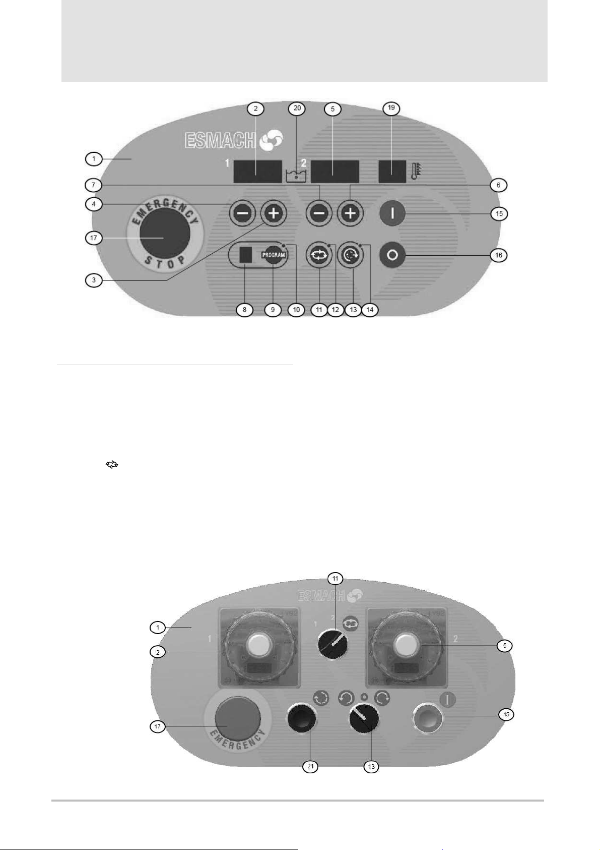
With reference to Picture 2, the control devices, besides the main power switch Ref. 18 – Picture 4, are:
(1) control panel ( membrane keyboard panel )
st
(2) 1
speed working time display (timer) ( minutes.seconds until 9’.99”, minute for time ≥ 10’ only), while
operating it runs as a countdown. The operation mode “ water dispenser” shows the litres of water
(unit only) not yet added into the bowl compared to the set up value ( operates as a countdown)
st
(3) 1
(4) 1
(5) 2
(6) 2
(7) 2
speed working time “up” key or litres of water ( unit only) to pour into the
st
speed working time “down” key or litres of water ( unit only) to pour into the
nd
speed working time display (timer); it operates as display (2). Under operation mode “water
dispenser” its operating is like display (2) but referred to fractions (tenth-value) of litre
nd
speed working time “up” key or the quantity of water ( tenth of litre, for ex. = 0,4 litre)
nd
speed working time “down” key or the quantity of water ( tenth of litre, for ex. = 0,4 litre)
(8) According to the operation mode selected with ( 11 ), the display is :
- AUTOMATIC selected mode (led (12) on): no. of programm numbers from 0 to 9
- MANUAL selected mode (led (12) on) “-“; at the following start, letter H is shown on display
- WATER DISPENSER function activated letter W
(9) Key to select/confirm programm (led (10) on = in PROGRAMMING)
(10) PROGRAMMING led (red); see (9)
(11) Key to activate the operation mode: MANUALled (12) off, on display (8) is shown “-“; AUTOMATICled
(12) on; WATER DISPENSER led (12) off, W is shown on display (8), led (20) is on
(12) led (red) for running operation mode; see ( 11)
(13) Bowl REVERSAL key ( activated in1
st
speed only); by pressing it through impulse, a reverse bowl
direction is selected. Led (13): off= counter-clockwise rotation, on= clockwise
With protection grid closed: by keeping it pressed, bowl and spiral arm rotate, by releasing it they stop ; if
the grid is open while keeping the key pressed, the machine stops and the key must be released and
then pressed again to re-start the bowl rotation.
With protection grid open : by keeping it pressed, the bowl rotates; by releasing it the bowl stops; by
pressing the key again, the bowl rotates in the reverse direction compared to the previous and so on.
(14) Bowl direction reversal led (red); see (13)
(15 START key; in AUTOMATIC and MANUAL mode, it starts the spiral arm and the bowl; in WATER DISPENSER
mode, it allows the addition of water in the bowl for the maximum of the water quantity set up.
(16) STOP key (normal stop); in AUTOMATIC and MANUAL mode, it stops the spiral arm and the bowl: (by
pressing it once, the residual operating times are stored, by pressing it twice, instead, the operating
residual times are zero-adjusted as at the end of cycle), in WATER DISPENSER mode, it stops the water
flow, the countdown in (2) and (5) stops; if (15) is pressed, the countdown re-starts from the point it had
stopped before; if instead, (16) is pressed again all initial water values are re-established again on
display
(17) Emergency stop button ( red mushroom-headed button on a yellow base); once pressed, it remains in
this position, allowing the stop of the machine and setting to zero the electric power of each of its parts,
otherwise dangerous, in particular of motor (displays (2) and (5) show “- - -“ and “- - - “ )
(18) Main switch ON/OFF; it can be locked in position OFF by removing the lever and passing a lock with
key into the hole concerned
(19) Mixture temperature display (for machine with the measurement system concerned only; see the end
of par. 2.1.)
(20) WATER DISPENSER operation mode led ( blue) led; see ( 11)
Page 11
p. 76
Esmach S.p.A.
Grisignano di Z
occo (VI)
- I
SPI 30-200 F
Instructions for use
and maintenance
Picture 2 - E Version: Control Panels and Control Devices
M Version (ELECTRO-MECHANICAL CONTROLS )
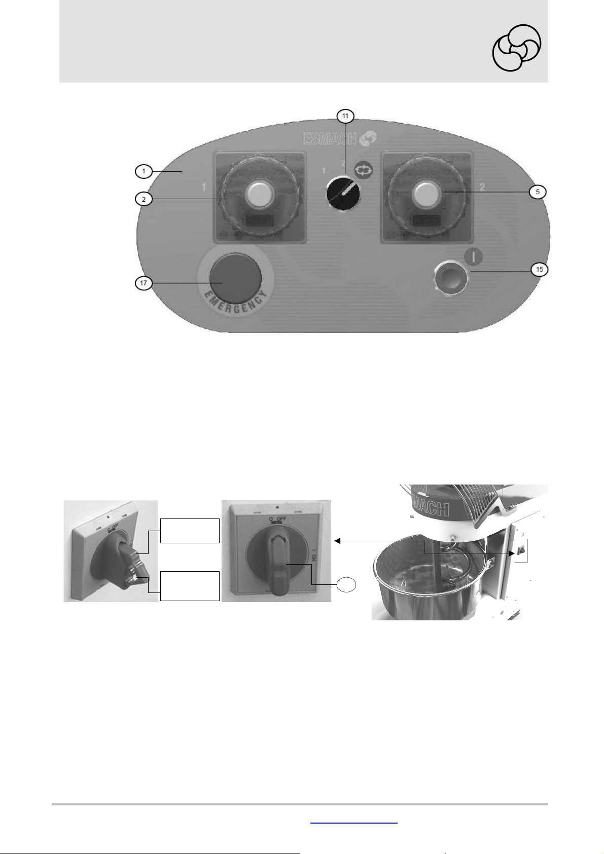
With reference to Picture 3, the control devices, besides the main power switch Ref. 18 – Picture 4, are :
(1) Control panel
(2) Electromechanical display (timer) to set the 1
(5) Electromechanical display (timer) to set the 2
(11) Selector to activate alternately the following operation mode:
- pos. 1: the machine operates non-stop in 1
- pos. 2: after an initial operating at 1
nd
in 2
speed; the timer are excluded
st
speed for a time of 120 seconds, the machine operates non-stop
- pos. : both timers are enabled; its operating is based on the set up times, except for the first 120”
during which the machine operates in 1
st
speed working time
nd
speed working time
st
speed; the timers are excluded
st
speed
(13) (SPI 60-80-100-130-160-200 only) 3-position-selector for the bowl rotation direction
Left hand position= counter-clockwise (overhead view); central position= bowl still; right hand position=
clockwise (overhead view )
(15) Start button (start)
(17) Emergency stop button ( red mushroom-headed button on a yellow base); once pressed, it remains in
this position, allowing the stop of the machine and setting to zero the electric power of each of its parts
(21) (SPI 60-80-100-130-160-200 only) bowl rotation “dead man” button (after releasing it, the bowl stops) ;
it is normally used for impulse rotation of the bowl. .
SPI 60-80-100-130-160-200
Page 12
s
ervice@esmach.com phone +
39 0444 419762
www.esmach.com
p. 77
hole
SPI 30-45
Picture 3 – M Version: Control Panels and Control Devices
2.3 MAIN POWER SWITCH
Each machine is equipped with a main power switch as per position shown in Picture 4.
English
lever
Lock
18
Picture 4 – Main Power Switch
Page 13
p. 78
Esmach S.p.A.
Grisignano di Z
occo (VI)
- I
SPI 30-200 F
Instructions for use
and maintenance
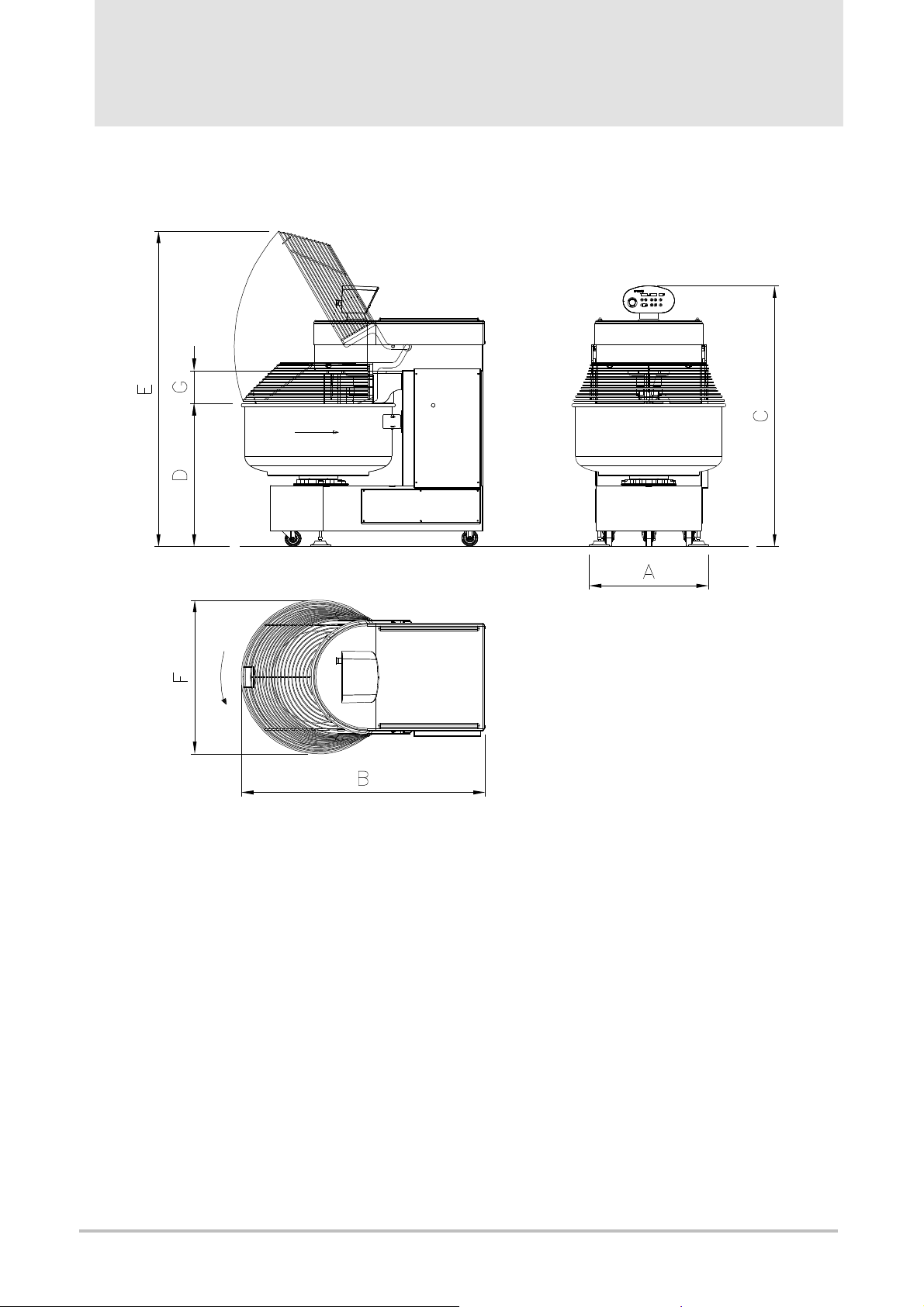
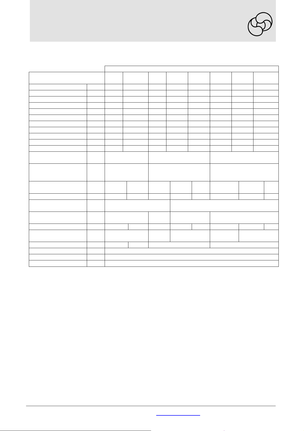
2.4 MAIN TECHNICAL FEATURES
Picture 5 – Machine Dimensions
Page 14
s
ervice@esmach.com phone +
39 0444 419762
www.esmach.com
p. 79
SPI
30 45 60 80 100 130 160 200
English
TECHNICAL
SPECIFICATIONS
A mm 477 477 588 588 588 735 735 735
B mm 978 978 1121 1207 1207 1413 1495 1495
C mm 1378 1378 1563 1563 1563 1610 1610 1610
D mm 741 791 891 886 936 862 883 943
E mm 1879 1864 1679 1751 1776 1864 1945 1975
F mm 562 562 638 741 741 847 948 948
G mm 181 131 184 189 139 222 202 142
Machine Mass kg 218 222 385 417 417 624 680 705
Mass on a Pallet only kg 239 243 420 452 452 660 716 741
Mass on a Cage kg 301 305 504 536 536 744 800 825
Mass on a Case kg 323 327 581 613 613 765 821 846
Machine Overall
Dimensions on Pallet
mm 1150x650x1550 1300x850x1730 1600x1000x1750
Packaging Overall
Dimensions (wooden-
mm 1250x750x1670 1400x950x1820 1700x1100x1850
cage/case)
Mixture Capacity
min./max. (a)
kg 2/30 2.5/45 3/60 3.5/80
4/10
0
4/130 4.5/160
4.5/
200
Bowl Capacity L 50 60 95 120 145 200 250 290
1st/2nd Spiral Arm
Rotation Speed
1st/2nd Bowl Rotation
Speed
r.p.m
.
r.p.m
.
103/206 107/214
10/20 7.5/15 8/16 10.8/21.6
Installed Power kW 1.5 1.5 2.75 4.55 4.55 6.8 8.4 8.4
Spiral Arm Motor
Power
kW
1.5-0.75 (b)
2.2 -
1.5
4 - 3 5.9 - 4.05 7.5 - 4.8
Bowl Motor Power kW - - 0.55-0.37 0.9-0.45
Voltage (c) V 400
Frequency (c) Hz 50
No. of Phases (c) -
3 ∼ + PE
(a) the max. mixture capacity shown, refers to a water/flour ratio not less than 60% ( flour W= 250, P/L=
0,4); it reduces in the ratio reduction:(water quantity)/(flour quantity)
(b) same motor both for spiral arm and bowl
(c) these values represent the most frequent case; should voltage and/or frequency and/or no. of phases be
different, the specifications shown on the identification plate will be valid only ( see par. 2.5)
Page 15
p. 80
Esmach S.p.A.
Grisignano di Z
occo (VI)
- I
SPI 30-200 F
Instructions for use
and maintenance
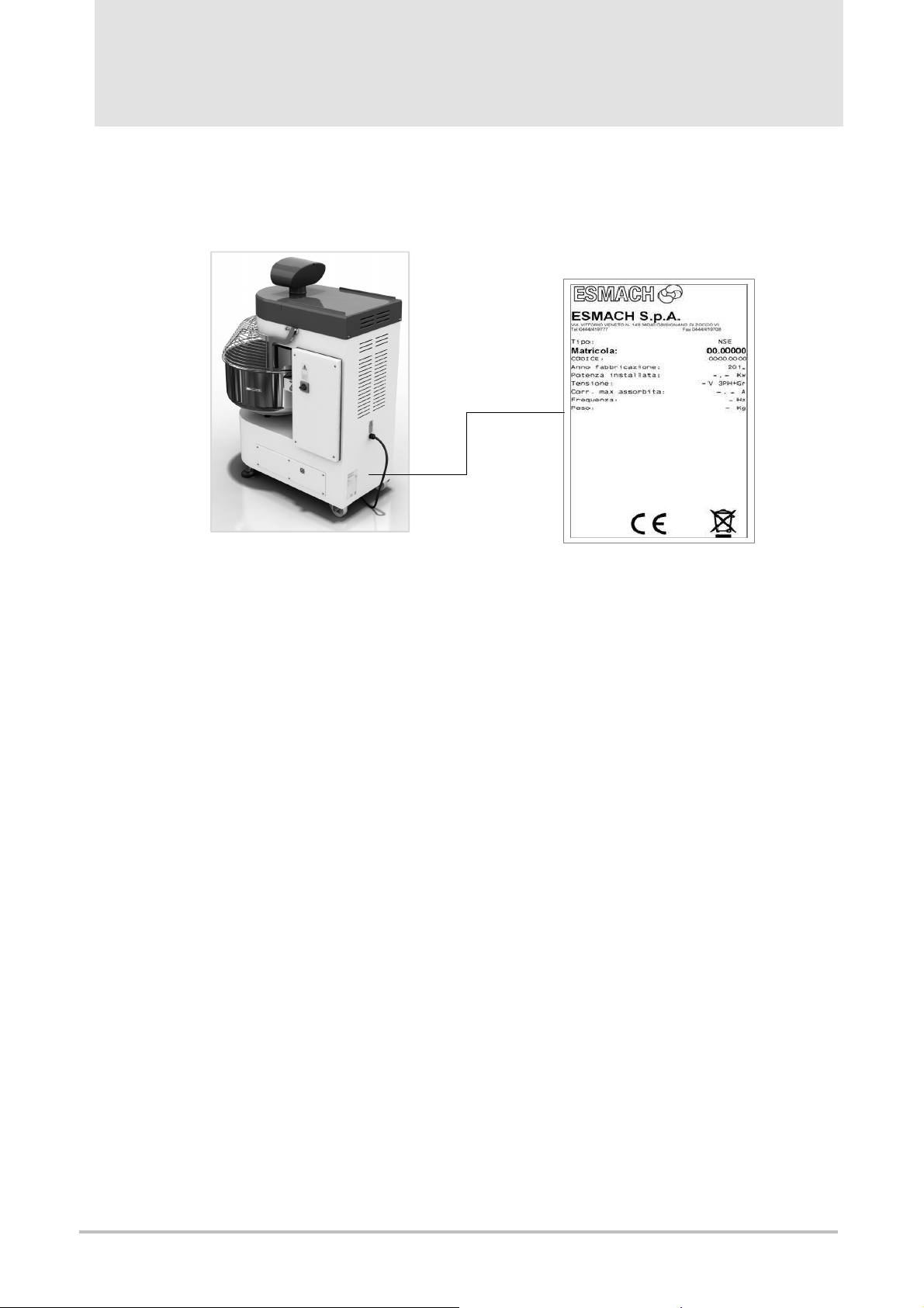
2.5 IDENTIFICATION PLATE
The plate, on which the following CE mark, manufactures’s specifications, number of registration, year of
construction, weight, electrical data are indelebile reported, is stable fixed on the machine as shown in
Picture 6. .
Picture 6 – Identification Plate and its Placement
3 INSTALLATION AND USE
3.1 INSTRUCTIONS REGARDING THE INSTALLATION ROOM
The place where the machine shall be installed and/or used shall have to comply with the existing laws and
standards in order to assure an adequate protection from any impact, damage, deterioration and weathering
agents as well. All access ways are to be easily accessible and wide to allow the crossing of the machine
without any risk both for the operator’s physical integrity and the integrity of the machine as well. The floor
and the main structures shall have the features according to the existing laws and standards considering the
whole load to support and safety factors concerned; floor and room walls must be easy to clean, to disinfect
and disinfest.
The floor has to be flat, without inclination, compact and free from any holes and roughness.
The electrical equipment and the equipotential protection system (ground) of the site shall have to comply
with the existing laws and standards; they shall have to be carried and maintained and, where prescribed by
the law, checked periodically by authorized and qualified engineers, enabled to issue the eventual
declaration of conformity concerned.
On the power supply panel any suitable protection devices are to be installed against overload current, short
circuit and phase-phase, phase-neutral (if concerned), phase-ground failure.
3.2 TRANSPORT, HANDLING AND LOADING
Depending on destination and contractual agreements, the machine shall be delivered wrapped in a
thermoshrinking plastic film bag and placed on a pallet or in a wooden-cage or a wooden-case.
Before dispatching it from the Manufacturer’s site, the machine is put and fixed onto a wooden-pallet; then
the pallet, the cage or the case shall be further fixed on the platform of the mean of transport through
wooden blocks/supports, loaded and/or bound to resistant points of the mean of transport in order to avoid
any motion during their transportation.
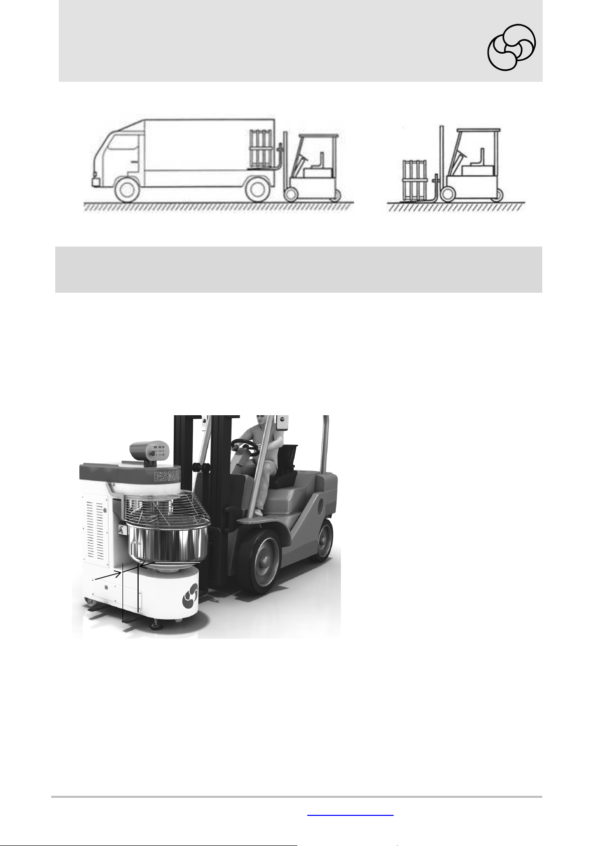
To lift and handle the pallet, the cage or the case use a suitable fork lift truck (the mass is shown in par. 2.4
and on the identification plate); the lifting forks are to be introduced in the pallet or in the base of the cage
seat concerned and have to protrude to the opposite side for 200 mm at least as shown in (Picture 7).
Page 16
s
ervice@esmach.com phone +
39 0444 419762
www.esmach.com
p. 81
≥ 200
English
Picture 7 – Pallet or Cage Lifting up and Handling by means of a Fork Lift Truck
CAUTION!
No different lifting devices and/or systems from the ones described are to be used.
Adopt all possible precautions in handling and/or transporting the machine and its parts in order to
avoid or reduce any risks to people, animals or things.
Remove any eventual packaging from the machine; in this case separate the different materials per type of
packaging ( rivets, plastic, wood etc) and place them in a suitable waste collection point, accessible to
authorized personnel only and waiting to be collected from the disposal firms concerned. The waste
disposal, according to the strict regulations and respect of the environment, are obligations clearly
and unequivocally imposed by the existing laws.
Check the integrity of the machine in all of its parts; in case of doubt contact the Manufacturer.
To move the machine from the pallet or from the cage and, in general, to lift the machine released from its
packaging, and according to the devices at disposal, it is allowed to :
a) use the fork lift truck with a suitable capacity ( the mass is given in par. 2.4) as shown in Picture 8.
Picture 8 - Machine Lifting up by
b) use a suitable lifting belt ( the mass is given in par. 2.4) to connect to a lifting device hook ( bridge crane,
console table crane, jib crane, etc.). In this case the lifting belt end extremities cannot be lifted up by
means of the forks of the forklift truck: the load would not be protected against falling down and could
cause a rolling over of the fork lift truck. The lifting belt has to be 3 m long at least and has to go across
under the head of the base as follows (Picture 9) :
- remove the top cover of the head (the part without control panel only) following the instructions given in
par. 4.3.2 ( cover (1) Picture 14); if a rocker arm suitable to lift load is at disposal, no cover removal is
necessary
- lift the bowl cover and let one belt extremity (eyebolt) go through between the spiral arm and the flour
guard ; when the eyebolt is out from the head of the base, hold the belt horizontal ( in plane) and
introduce it between the flour guard and the head of the base (Picture A)
means of a Fork Lift Truck
Page 17
p. 82
Esmach S.p.A.
Grisignano di Z
occo (VI)
- I
SPI 30-200 F
Instructions for use
and maintenance
- lower the bowl cover ( Picture B)
- connect the end extremities of the lifting belt to the lifting device (Picture C); with the lifting belt centered
between the spiral arm and the column of the base (elements, not allowing the side motion of the belt), the
load results to be well balanced.
After completing this operation, it is necessary to lift up the cover before driving out the lifting belt and
then to move the belt towards the spiral arm to avoid that the eyebolt, in taking the belt off, remains fixed in
between the flour guard and the head of the base.
Lift slowly the machine avoiding any impact and swinging.
Rest the machine on the ground, in a safe and protected room free from any risk of damage.
Once placed on the ground the machine can be moved in pushing it, as it is equipped with 3 caster wheels.
In positioning the machine, keep sufficient free space all around it in order to operate in a comfortable way
during the normal production ( 1 m per each side is normally sufficient).
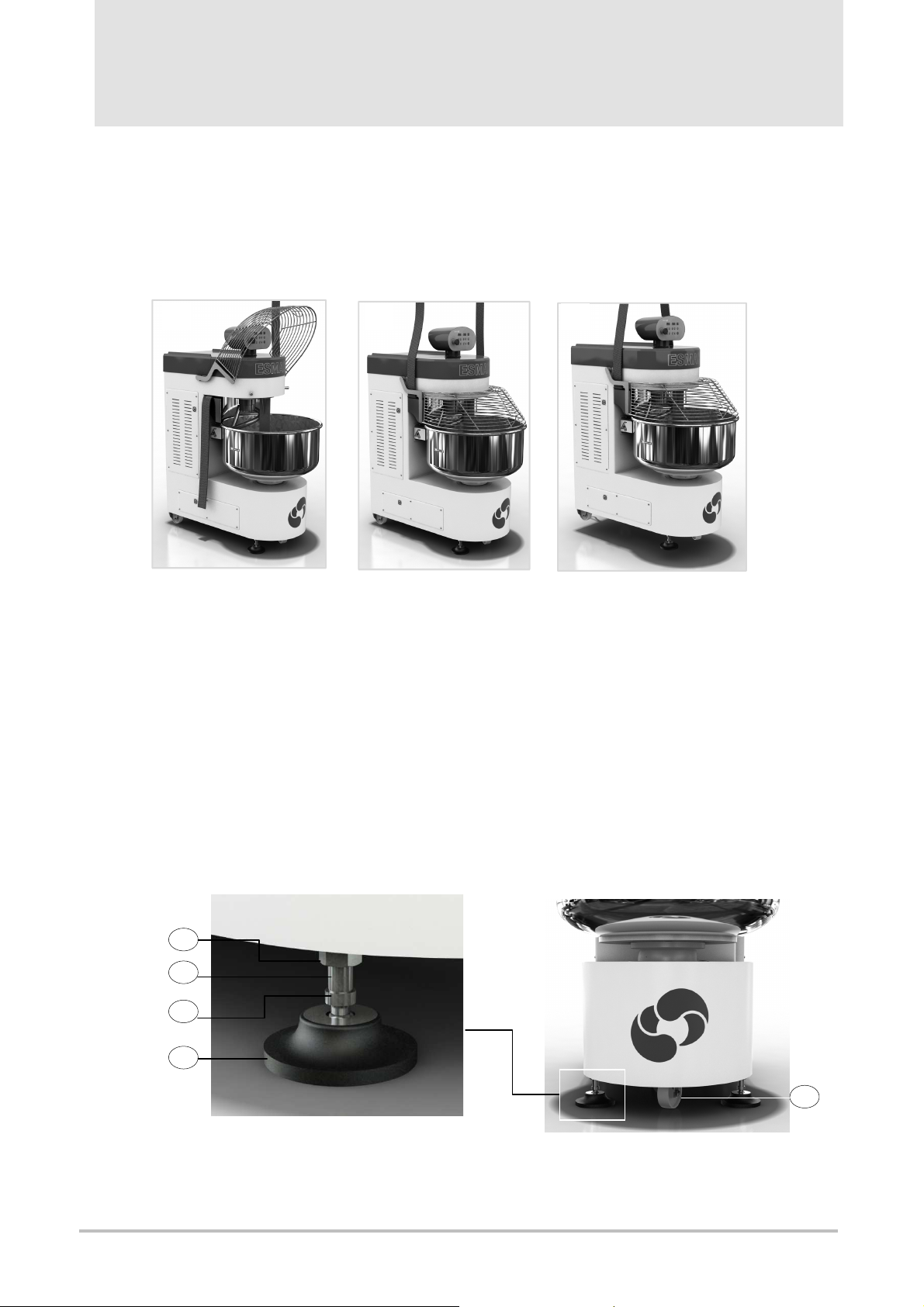
With reference to Picture 10, fix the machine in the room where it shall be used, by using the support feet
(1):
- unloose the lock nut (2) by means of a hallen wrench;
- rotate the foot (1) clockwise (overhead view) by means of a hallen wrench in the shaft facets(3); this
operation is to carry out in the same way for both feet;
- when the front wheel (5) will be unloaded from the weight of the machine, lock each foot in tigthen the nut
(2); keep the threaded shaft (4) fixed by means of the wrench introduced in the facets (3)
Should it be necessary to move the machine again ( for example to clean the floor), a reverse operation is to
be carried out, i.e. through the unloading of the weight from the feet and placing the machine on the caster
wheel (5)
A B C
Picture 9 – Maschine Lifting up by means of a lifting Belt
2
4
3
1
5
Picture 10 - Support Feet
Page 18
s
ervice@esmach.com phone +
39 0444 419762
www.esmach.com
p. 83
English
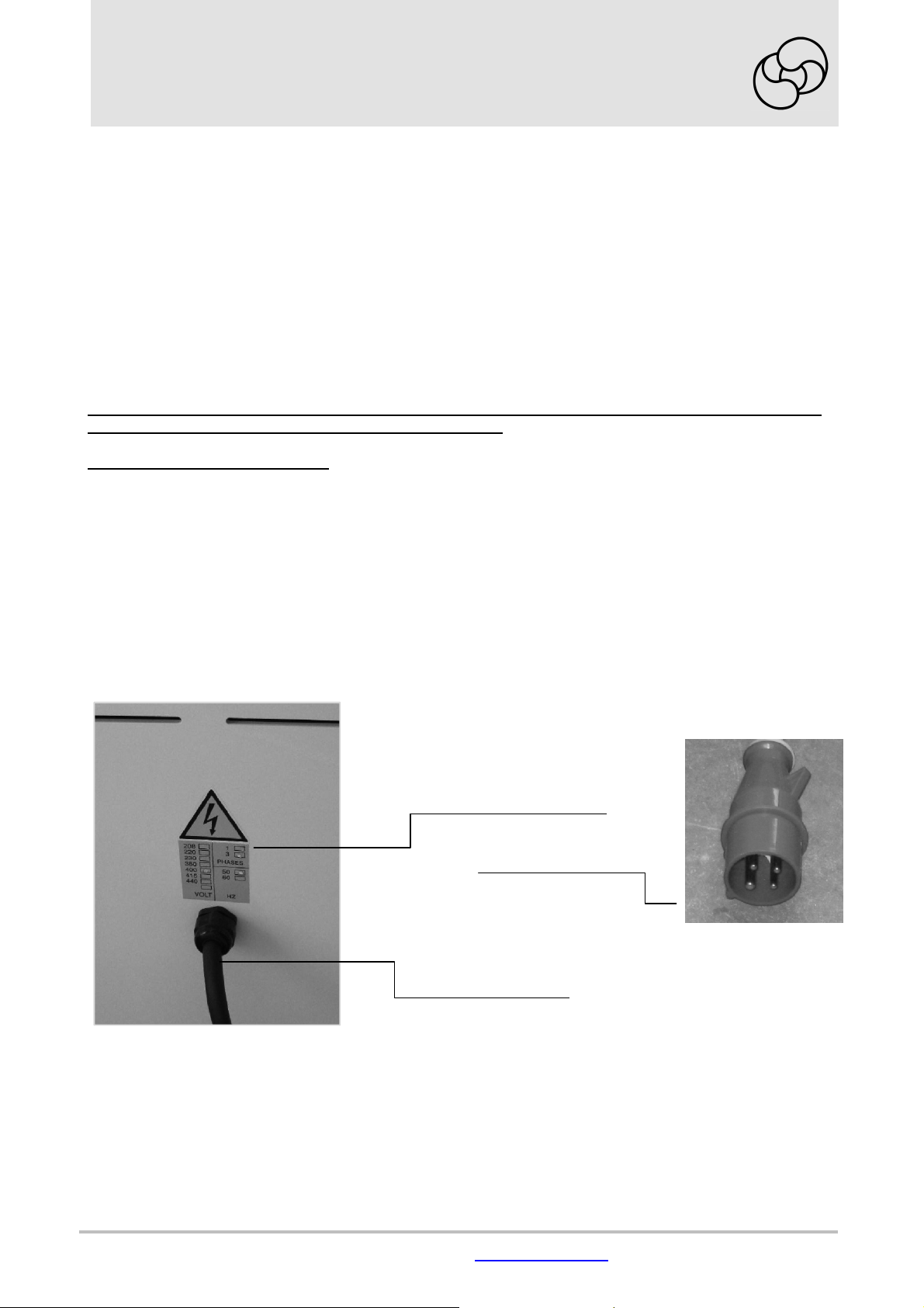
3.2.1 ELECTRICAL CONNECTION
Any elctrical intervention involving the working site is to be carried out by qualified and skilled technicians,
having a technical knowlege and a knowlegde of the standards concerned to carry out operation properly
done and on safety conditions according to the existing laws and standards; they shall be able to issue the
declaration of conformity concerned and required by the law. After delivering the machine and before
proceeding to the electrical connection, ensure that voltage, frequency and number of phases are the
same declared by the Manufacturer and shown on the identification plate; voltage, frequency and
number of phases are also reported on a adhesive label placed at the back of the machine, in vicinity of the
point where the power supply cable enters the base. In any case, refer always to the technical
specifications shown on the identification plate only (paragraph 2.5).
The machine is delivered complete with cable and 4-pole plug ( 3-phase poles + 1 ground pole PE); see
Picture 11.
Use the ground system concerned , the efficiency of which has to be periodically tested and do not connect
to any gas or water pipes or other generic metallic structures .
For connections in the US/Canada:
An electrician licensed under the jurisdiction (city, municipality, county, state, etc.) in which the mixer will be
installed must install the plug that meets requirements in sub-clauses 4.5.2.2 of C22.2 No. 195
and 6.2.1, 11.1.1, 15.1.6 of UL 763.
The power supply cable is to be kept far of warm parts and/or parts in motion and has not to be an obstacle
for people, animal or things.
The plug has to be easily accessible and as visible as possible too.
Once the plug has been connected to the power supply socket, check the correctness of the bowl and spiral
arm rotation direction: i.e. clockwise on normal conditions (overhead view); if the rotation direction is not
correct, invert the two phases in the plug ( do not disconnect the ground cable from its clamp) but this
operation has to be carried out by a professionally qualified electrician only.
Picture 11 - Power Supply Cable with Plug
Adhesive label showing
Voltage, Frequency and no.
of Phases
Electrical Connection Plug
Power Supply Cable
Page 19
p. 84
Esmach S.p.A.
Grisignano di Z
occo (VI)
- I
SPI 30-200 F
Instructions for use
and maintenance
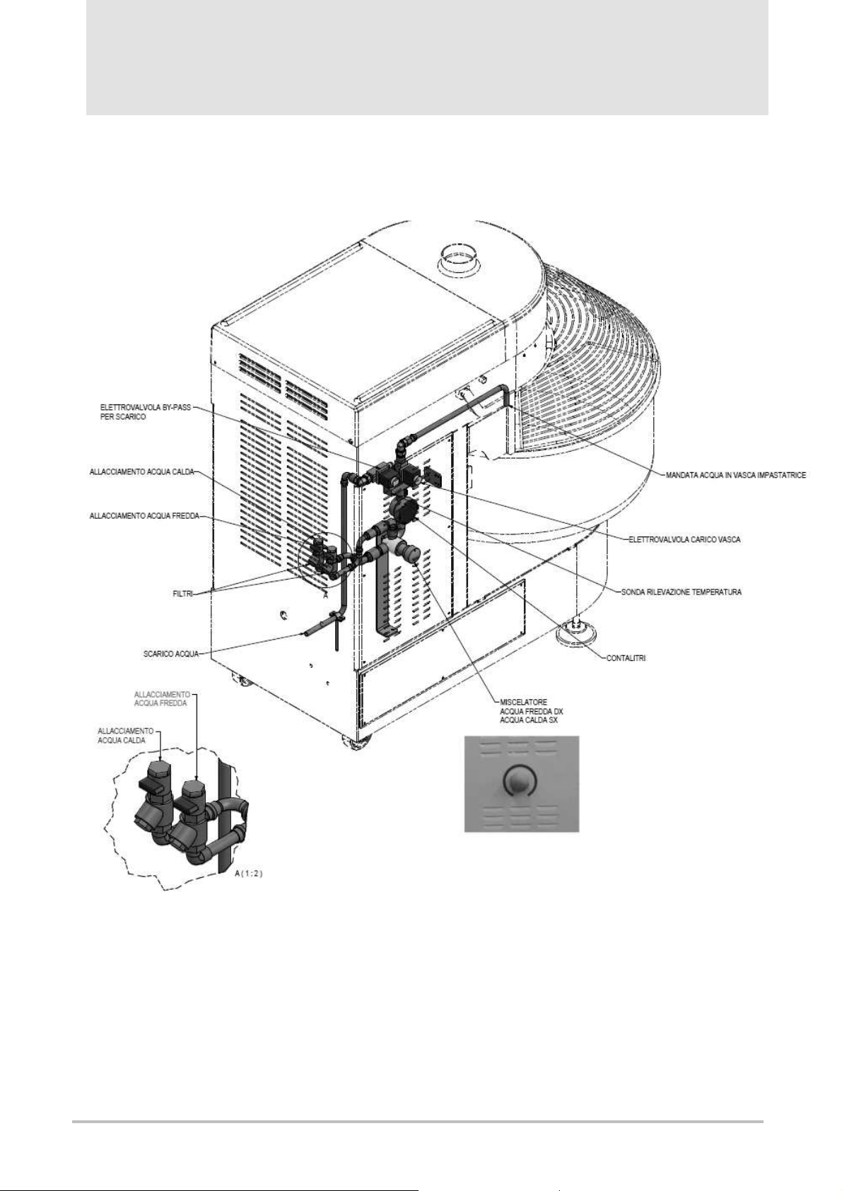
3.2.2 HYDRAULIC CONNECTION
(for machine equipped with “water dispenser” system only)
Picture 12 – Hydraulic System on Machine Board (option)
Page 20

s
ervice@esmach.com phone +
39 0444 419762
www.esmach.com
p. 85
English
3.3 OPERATING AND USE
The use of the machine is allowed to authorized and qualified personnel only, skilled and able to use
machines for bakery and pastry mixture, properly educated and trained about the correct and safe
use of the machine and informed on the risks concerned and the measures to take in order to
eliminate or reduce them accordingly.
An only one operator at a time is allowed and has to work at the machine.
The instructions contained in the present manual are sufficient and adequate; however, on specific request
and previous agreements, the Manufacturer can provide education and training , as well as information
required for a safe and correct use of the machine at its manufacturing facilities or at the principal’s/user’s.
It is under the user’s responsibility to choose and nominate the most suitable people to operate the machine,
inform and train them accordingly.
ATTENTION!
It is strictly forbidden to carry out operations on and/or through the machine without owing the
necessary skills required and described in this manual.
In compliance with the existing laws regarding health and safety at work place, the Company employer has
to carry out a suitable and adequate information, education, training activity for the personnel
authorized to the use of the machine and implement any any operational procedures suitable for reducing
as much as possible the exposure to any eventual residual risk ( see par. 5.2).
The manufacturing company declines any responsibility for damage to people, animals and things due to a
non-observance of the instructions described in this manual.
3.3.1 GENERAL INFORMATION ABOUT THE NORMAL USE
Before starting the normal user, the following important remarks are to be taken into consideration:
1. At the beginning of each working day and/or shift, check the integrity and fixation of the protection
covers and the efficiency of the safety devices according to paragraph 5.2.3.
2. To load the flour in the bowl, do not empty the flour sack quickly into it; instead, whenever possible, lean
the sack, possibly and already partially discharged, on the bottom of the bowl, according to the
instructions given here below, and then open the sack at the bottom base and let the flour spill out
slowly in order to generate as few flour dust as possible; each next sack, after lightening according to
the following instruction, is to be held slightly inclined, with the opening near the flour already
poured in; then let the flour go out slowly in order to limit the flour dust development as much as
possible. During the mixing operations, do not scatter the flour on the dough by using the hands from
the above, through the cover openings; try instead to stop the machine, to lift up the cover and scatter the
flour in a due necessary quantity with the hands or by means of a bailer and staying as near as possible
to the dough and without any sudden movements.
CAUTION!
A manual handling of flour sacks may carry ergonomic risks causing possible muscle and skeletal
injuries; it is safer to unload the sack before, in removing as much flour as possible, by means of a
bailer, and then when just a few kilograms of flour remain in the sack, to lift it up manually and pour it
into the bowl, following the above mentioned instructions.
3.The same procedure is to follow when water is to pour into the bowl; add just a few litres at once instead
of full and large recipients. If possible, install an automatic “water dispenser” system to implement nearby.
4. During the normal use of the machine in production, no particular IPD (individual protection devices) are
requested, except for particular requirements and specifications which may arise from the risk assessment
regarding the health and the safety of operators and that the company employer has to carry out in
compliance with the existing law regulations. If, for example, sacks of flours were poured quickly into the
bowl and/or from the edge of the bowl, despite the instructions mentioned above, this would cause a flour
dust dispersion wave in the air, with a consequent risk for the health of people exposed nearby, in case of
inhalation ( asthma, rhinitis, tearing etc.); in this case, besides the safety reinforced toe shoes, the operator
shall have to wear a respiratory apparatus protection mask with filtrating capacity suitable for the flour dust
granulometry (reported in the technical sheet of the flour, if available, or, in any case, to be defined and
measured by the company employer) and make sure that nobody is nearby before emptying the flour sack
into the bowl. It is responsibility of the company employer to identify further IPD to wear for different
purposes, as for ex. to preserve the hygiene of the food ingredients.
Page 21

p. 86
Esmach S.p.A.
Grisignano di Z
occo (VI)
- I
SPI 30-200 F
Instructions for use
and maintenance
5. During any cleaning operations, wear reinforced toe shoes, water-proof gloves and dust-proof
protection mask, as above described.
6.The machines equipped with a bowl grid cover are conceived and developed in such a way that at the
start the spiral arm and the bowl rotate at the lower speed (1
contain as much as possible the development of flour dust dispersed in the air; even if the operator sets a
lower time than 120 seconds, the display concerned shall start the countdown starting from 120 seconds.
For the machines equipped with bowl full cover, the minimum rotation time in 1
7.Do not try to reclaim the flour stored on the inside walls of the machine; this might cause a contamination
of the food ingredients with a consequent risk for the consumers’ health and a risk for the operator’s safety
in case of hand, finger etc. introduction in the limited spaces reserved to any gears in motion ( for ex.:
between bowl board and cover, wall and base column etc. )
8.To activate the normal stop, press STOP (16) Picture 2 - E Version: Control Panels and Control Devices.
9.If the emergency stop button is pressed (17) Picture 2 - E Version: Control Panels and Control Devices
the machine stops immediately and the electrical power supply to the motor(s) is set to zero. To re-start the
machine, it is necessary to set up the emergency button ( rotate it in the direction shown by the arrow). The
emergency stop button is to be used in case of real emergency only.
10.The same result is obtained in lifting up the bowl cover for a few centimetres; in this case close the cover
completely before restarting the machine. On normal conditions, do not stop the machine by lifting up
the cover in order to keep the safety system efficient as longer as possible, but use the button (16) Picture 2.
11. Before dipping ( for machine equipped with this option only) the probe to measure the temperature of the
dough, stop the machine through the button (16) Picture 2. After stopping the machine only, lift up the
cover of the bowl, if required, to proceed with the temperature measurements.
12.The access to the adjustment devices and the adjustments of the same are permitted to a trained and
authorised personnel only; it is responbibility of the company employer to identify the most suitable
personnel and inform the other workers about their obligations to address to them if needed.
13. In the farest point on the bowl cover, compared to the spiral arm, is a small opeing to allow the operator
to “touch” the dough consistency with one hand; in carrying out this operation keep the hand in the shape
of the opening and touch just the dough on the surface only, and take some small pieces if needed. For
any reasons do not put the hand in the dough while the bowl is in motion: the risk that the arm is
involved and pushed against the opening edge would be high and could cause injuries, even if
probably slight. Do not put the hand towards the operating area of the spiral arm due to the risk of
crushing and shearing between spiral arm and central bar with severe affection for the safety of
the operator exposed.
14.After removing the finished dough from the bowl, divide it into small portions, according to size and
weight to be easily worked and without any risk. A very heavy and bulky dough is difficult to lift up and
“keep still”; the dough is in fact extremely unstable ( and the more unstable the higher is the water
percentage compared to the flour ), it stretches downwards and it is difficult to hold in the hands, except for
small portions. This instability may cause continuous variations in the barycentre of the mass handled
manually and also on the balance and effort conditions the operator has to carry out to keep it.
Considering that the operator has to bend his breast in taking and lifting up the portion, it is easy to
understand how higher the ergonomic risk is ( and of muscle-skeletal injuries) while increasing the portion
mass to handle manually.
15. For any reasons do not put your hands between the bowl while rotating and the wall of the base column;
the distance between the two parts meets the safety requirements, however the residual risk of gripping
and pulling remains if a person puts heavy the hand or also the arm into this passage way.
16. IMPORTANT NOTICE! If the machine is associated to a lifting/pouring device from our manufacturing
line, please read carefully the user’s manual referred to this machine.
17. IMPORTANT NOTICE! Before starting the machine, observe the following instructions:
a) Ensure that the voltage in the socket, the power supply cable plug has to be connected to, refers to
the one declared by the Manufacturer ( par. 2.4) and shown on the identification plate (par. 2.5). If
not, do not carry out any electrical connection and contact the supplier or the manufacturing
company.
b) Check the rotation direction of the spiral arm, which has to be counter-clockwise ( overhead view)
st
speed ) for 120 seconds at least, in order to
st
speed is 2 seconds. .
Page 22

s
ervice@esmach.com phone +
39 0444 419762
www.esmach.com
p. 87
English
3.3.2 MACHINE START-UP
After connecting the machine to the power supply socket, switch on (ON) the main power switch (18)
3.3.3 “MANUAL” OPERATING MODE
E Version ( ELECTRONICAL COMMANDS; see picture below )
To operate in MANUAL mode the led (12) has to be off and the display (8) has to show “H”; if the led (12) is
on, press the button (1) once.
To start the machine in 1st speed , press the button (15); the display (2) starts to count and shows the 1st
speed working time run.
To let the machine operate in 2nd speed, press again the button (15); the display (5) starts to count and
shows the 2nd speed working time run; if the display(5) is blinking, this means that the 1st speed minimum
working time ( 2 minutes or 2 seconds depending on the bowl cover, i.e. grid or full cover) has not yet
elapsed.
To return to 1st speed operating, it is sufficient to press again the button (15).
To stop the machine on normal conditions, press the button (16); in this case the timers remain stopped at
the time shown after stopping; if the button (15) is pressed again, they re-start to count from the point it had
been interrupted.
To set both timers to zero, press the button (16) twice; the displays (2) and (5) shall indicate “000” and “000”.
Page 23

p. 88
Esmach S.p.A.
Grisignano di Z
occo (VI)
- I
SPI 30-200 F
Instructions for use
and maintenance
M Version (ELECTRO-MECHANICAL CONTROLS; see picture below)
To let the machine operate continuously in1st speed, put the selector (11) in position 1.
To let the machine operate continuously in 2nd speed, put the selector (11) in position 2; before switching to
the 2nd speed, the machine shall operate in 1st speed for the minimum working time ( 2 minutes or 2
seconds depending on the bowl cover, i.e. grid or full cover)
Through the selector (13) it is possible to reverse the rotation direction of the bowl or to stop it ( for all
models, except for SPI 30 and SPI 45)
3.3.4 “AUTOMATIC” OPERATION MODE
E Version (ELECTRONIC CONTROLS )
To switch to AUTOMATIC operating mode, press the button (16) twice; the diplays (2) and (5) show “000”
and “000”.
Press the button (11) (the led (12) is on, then press again the button (9) until the number”0” is shown on the
display (8).
Set the 1st speed operating time on the display (2): press the button (3) to increase it, the button (4) do
decrease it.
Set the 2nd speed operating time on the display (5): press the button (6) to increase it, the button (7) do
decrease it.
To start the machine, press the button (15). The time on the display (2) decreases progressively; when it
reaches the 0 (zero), the machine switches automatically to the 2nd speed and starts decreasing the time on
the display (5).
To switch to the 2nd speed before the elapsing of the time set for the 1st speed, it is necessary to set to zero
the count on the display (2) in pressing the button(4); this shall be possible if the machine has already
operated at 1st speed for the minimum time foreseen for the default ( 2 minutes or 2 seconds, depending on
the type of cover the machine is equipped with, i.e. grid or full cover).
To stop the machine keeping in storage the elapsed time, press the button (16) once, to re-start press the
button (15) ( the count of time starts again from the point it was interrupted).
To stop the machine and set to zero the operating time already elapsed, press the button (16) twice; the
time set at the beginning will appear again on the displays (2) and (5)
Page 24

s
ervice@esmach.com phone +
39 0444 419762
www.esmach.com
p. 89
English
M Version (ELECTROMECHANICAL CONTROLS )
To let the machine operate according to the time set on the timers (2) and (5) , through the automatic
switching from the 1st to the 2
nd
speed, take the selector (11) in position , once the time set for
the 1st speed has elapsed and without prejudice to the minimum operating time at 1st speed ( 2 minutes or
2 seconds, depending on the type of cover the machine is equipped with, i.e. grid or full cover).
To set the time on the timers (2) and (5), turn the front disc until the red indicator coincides with the slot
referring to the time needed.
Through the selector (13), it is possible to reverse the rotation direction of the bowl or to stop it (the models
SPI 30 and SPI 45 are not equipped with the device (13) and the device (21)).
3.3.5 “E” VERSION MACHINE: WORKING CYCLE PROGRAMMING AND OTHER PARAMETERS
3.3.5.1 BASIC MACHINE: MIXTURE TIME PROGRAMMING
To select a program, press the button (9) more times, until on the display ( 9) the number of the program
requested is shown. The program numbering is from “0” to “9”, but only the programs from “0” to “9” are
developed in such a way, that it is necessary to go on PROGRAMMING to modify the time stored; the program “0”
(zero) keeps in storage the latest value, set up by the operator, through the AUTOMATIC operating mode.
Page 25

p. 90
Esmach S.p.A.
Grisignano di Z
occo (VI)
- I
SPI 30-200 F
Instructions for use
and maintenance
As an example : if, after selecting the program “0”, the operator sets up 4 minutes for the 1st speed and 8
minutes for the 2
program “0”, the operator sets up 3 minutes for the 1st speed and 6 minutes for the 2
will be stored and next time the machine shall operate according to the latest times set up and stored, if no
new times to set up are required.
For all the other programs from “1” to “9”, instead, the stored times remain unchanged; once the program has
been loaded and should the operator have to change the time on the displays (2) and (5) ( for ex.: because
he realizes that the mixture needs different times at that moment), the times effectively stored in the program
can be loaded again at the end of the cycle; it is possible to change the times by entering through the
PROGRAMMING mode and acting as mentioned here below:
-select the number of the program needed by pressing repeatedly the button(9)
-keep the button (9) pressed for about 3 seconds: the display (8) starts blinking and the led(8) switches on
-set the 1st speed operating time on the display (2): press the buttons (3) to increase it, (4) to decrease it
-set the 2nd speed operating time on the display (5): press the buttons (6) to increase it, (7) to decrease it
To store the set up times in the selected program, press the button (9) for about 3 seconds: the display (8)
stops blinking and the led (10) switches off.
To quit the program without storing the set up data, press the button (16)
At this time, after selecting the program concerned, by pressing the button (15), the machine shall carry out
the mixture cycle observing the times stored for the two speeds through an automatic switching from the 1st
to 2nd speed, once the time set up for the 1st speed has elapsed.
To switch to 2nd speed before the time given for the1st speed has elapsed, set to zero the count on the
display (2) by pressing the button (4); this shall be possible however if the minimum time foreseen per
default for the 1st speed (2 minutes or 2 seconds, depending on the type of cover the machine is equipped
with, i.e. grid or full cover).
To stop the machine keeping in storage the elapsed time, press the button (16) once; to re-start press the
button (15) ( the count of time starts again from the point it had been interrupted).
To stop the machine and set to zero the operating time already elapsed, press the button (16) twice; the
time set at the beginning will appear again on the displays (2) and (5).
3.3.5.2 MACHINES WITH MIXTURE TEMPERATURE MEASUREMENT SYSTEM
The temperature value measured is shown on the display (19); in the machines without any temperature
measurement system of the mixture, the display (19) is not activated ( not powered electrically).
The parameter P06 (see par. 3.3.5.6) allows to display the temperature in °C or °F.
While switching on, besides the functional control of the led, etc. C or F are also displayed in order to
understand if the unit of measurement has been selected ( i.e. Celsius or Fahrenheit grade).
nd
speed, these times shall be stored in the program “0”; if later, while using the same
nd
speed, these latter
Page 26

s
ervice@esmach.com phone +
39 0444 419762
www.esmach.com
p. 91
English
To measure the temperature of the mixture, the machine can be supplied complete with one of the following
devices:
-PT100 “immersion” probe ( par. 3.3.5.2.1)
-device for “infra-red” temperature measurement ( par. 3.3.5.2.2)
3.3.5.2.1 MACHINE WITH PT100 “IMMERSION” PROBE
If the machine is equipped with this device, the temperature measurement of the mixture is not allowed while
the machine is operating, because the dipping of the probe in the dough is to be carried out manually by the
operator. If the machine is in motion, the operator would not only be able to measure the temperature but
he would incur in the risk of being exposed to impacts or injuried if the probe were involved in the rotation
from the mixture. It not possible to associate a stop of the cycle after achieving a certain temperature, as the
machine stands still when the temperature is measured.
The probe can be dipped in the dough after stopping the machine only; this operation has to be carried out
when the bowl cover is open ( do not measure any temperature in introducing the probe through the opening
used to take a sample of dough : this operation is not only uncomfortable but also dangerous in case of an
accidental start given to the machine and with the probe dipped in the dough).
Do not press any key on the control panel when the probe is dipped in the dough inside the bowl.
The temperature value measured is shown on the display( 19).
3.3.5.2.2 MACHINE WITH “INFRA-RED” MEASUREMENT DEVICE
In this case the temperature measurement does not require any direct operation of the operator ( the device
is permanently installed under the head of the machine and executes its function without interruption).
According to the value assigned to parameter P07 ( see 3.3.5.6) the following alternatives are possible:
P07 = 0 check the mixture temperature without stopping the cyle; if the temperature value measured
exceeds the value set up, an acoustic alarm is activated through flashing and the display (19)
blinks showing the value of the temperature every 4 seconds.
P07 = 1 if the temperature value measured exceeds the value set up, this is detected through the
activation of a flashing acoustic alarm; the system controls the stop of the ongoing cycle and the
display (19) blinks showing the value of the temperature every 4 seconds. The operator can
allow the cycle to proceed by pressing the button START (15) or cancelling it by pressing the
button STOP (16).
P07 = 2 the value of the temperature measured is displayed only (flashing) without any further effect.
IMPORTANT REMARK: the acoustic alarm is activated the first time only when the temperature
measured exceeds the value set up in the program; for later exceedings, no acoustic alarm is
activated. In MANUAL operating mode, the temperature is shown on the display (19) only and no value
can be set up for it.
Page 27

p. 92
Esmach S.p.A.
Grisignano di Z
occo (VI)
- I
16
2 5
9
10
19
3
4 6 7
A
15
8
B
SPI 30-200 F
Instructions for use
and maintenance
3.3.5.2.2.1 HOW TO SET UP THE TEMPERATURE VALUE IN A PROGRAM
For each program ( from 0 to 9) a different temperature value can be set, but in the range between 0 °C and
65 °C (32 °F and 149 °F). To set and store the temp erature value in a program, proceed as follows:
-press repeatedly the button (9) until the program required is shown on the display (8)
-press the key PROGRAM (9) for about 3 seconds and keep it pressed until the led (10) switches on and the
display (8) starts blinking.
-press again the key (9) ( the display (19) blinks); set the temperature through the keys (3),(4),(6),(7)
-if the machine has no ingredient dispenser systems, by pressing the key (9) for 3 seconds, it is possible to
go out from PROGRAMMING (the led (10) switches off and the display (8)stops blinking), and the data are
saved; otherwise switch to the programming of the 1° dispenser ( par. 3.3.5.3)
If the set up temperature value has been exceeded, this may depend on the following :
a)machine not in operation: the display (19) blinks, showing the value of the temperature every 4 seconds
b)machine in operation: the display (19) blinks, as in case a), and ( only the first time when the temperature
value set exceeds, then no more) the acoustic alarm is activated for a time of 10 seconds.
The warning time is set up through the parameter P05 ( see par. 3.3.5.6)
3.3.5.3 INGREDIENT DISPENSER (D1 – D2 DISPENSER)
The machine is equipped with one or two dispensers; or it may be without any dispenser according to the
contractual agreement.
It is possible to program the delay time for each D1 and/or D2 dispenser, through which the ingredients to
distribute are to be added after the START or the advance time through which the beginning of the ingredient
addition is possible compared to the scheduled end of the cycle. The distribution occurs when the machine
is operating only, independent from the ongoing operation step, but it does not happen if the machine is in
STOP mode.
If the distribution has begun and the STOP button (16) is pressed or the bowl cover is lifted, the ongoing
distribution shall be completed.
The distribution time has to be always lower than the entire time of the cycle, i.e. than the sum of 1st e 2
speed mixture time ; in the case a higher time is set up ( and this is wrong!), while programming, the display
(2) shows ERR 009, the display (5) shows “d1” or “d2” depending of the dispenser concerned; it shall be
impossible to go out from PROGRAMMING.
For each program (from 0 to 9) it is possible to schedule different dispenser times:
-keep the key (9) pressed for about 3 seconds until the led (10) switches on and the display (8) starts
flashing
- press the key (9) until the display (19) shows a flashing “d1”; through the keys (3),84),(6),(7) ( - decrease +
increase ), set up the time needed ( advance or delay depending on how the parameter P09 has been set up).
If the machine is equipped with one D1 dispenser only, by pressing the key (9) for 3 seconds, it is possible to
go out from the PROGRAMMING and the data set are saved. Instead, if the machine is equipped with a
second dispenser, it is possible to switch to D2 dispenser programming, and this scheduling will follow the
same operation mode as described per D1 dispenser.
The choice of the “delay” time ( select “r”; see scheme below, Picture A) or “advance” time (select “A”, see
scheme below, Picture B) to begin the ingredient dosage is made in setting the parameter P09 for D1
dispenser and parameter P11 for D2 dispenser; for the two both the pre-set data is “delay”.
nd
Page 28

s
ervice@esmach.com phone +
39 0444 419762
www.esmach.com
p. 93
11 8
20
2
5
13
19
15
16
9
English
To modify the parameter P09 or P11, go to the user’s menu (see par. 3.3.5.6)
When the display (2) shows:
“_ d1” the parameter P09 is set up on “r” (see example below)
“_ d2” the parameter P11 is set up on “r”.
“d1_” the parameter P09 is set up on “A”.
“d2_” the parameter P11 is set up on “A”.
where: r = delay of distribution beginning compared to start
A = advance of distribution beginning compared to the end of the cycle scheduled
During the ingredient distribution, the acoustic alarm shall be activated for 5 seconds and the display (2)
shows “_d1” or “_d2” in an intermittent way
In the example shown below, the setting for D1 dispenser is the following:
« 5 minutes delay to start the ingredient dosage compared to the cycle start command ».
3.3.5.4 WATER DISPENSER
Check that the water pipe taps are running. To reach the water dispenser program, press the button (11)
the bowl cover has to be taken down), until the display (8) shows the letter “W”.
If no button is pressed after “W” displaying, the program of the previous mixture appears automatically after
30 seconds.
If after selecting the “W” program, the button +/- or the button (13) is pressed, the “W” mode remains
activated.
To go out from “W” selection, press the button (11), the system turns to the MANUAL program “-“
When the “W” program is selected, the blue led (20)
between the two displays (2) and (5) switches on.
The display (2) shows the number of litres to pour
into the bowl and to set up through the keys (3) and
(4).
The display (5) shows the number of deciliters to
pour into the bowl and to set up through the keys (6)
and (7).
To adjust the water temperature to put into the bowl,
turn the mixing handle control at the side of the
machine ( see picture 12, page 15) and at the same
time keep the button pressed (13) ( a by-pass valve
shall be activated allowing the water drainage
outside the bowl) until the value of the temperature is
shown on the display (19); in turning the handle
control clockwise, the water temperature decreases; it increases in counter-clockwise direction.
To start the water dosage, press the button (15) start.
The display (5) shows the value of the decilitres and the display (2) the value of the litres decreasing
progressively.
By pressing the button (16) stop, the water flow to the bowl is interrupted and the displays (2) and (5) blink.
By pressing the button (15) start, the water flow re-start from the point it had been suspended
Page 29

p. 94
Esmach S.p.A.
Grisignano di Z
occo (VI)
- I
MACHINE
LITRE MAX. VALUE TO SET FOR
SPI 30-200 F
Instructions for use
and maintenance
By pressing the button (16) twice, the water supply is set to zero, the displays (2) and (5) show the initial
values again.
When the water dosage is completed, the system switches to the previous mixture program automatically
(automatic from 0 to 9).
The values of litres and decilitres remain set up even if you switch from the mixture program and then you
come back to “W” program.
IMPORTANT NOTICE!
If during the dispenser, the voltage is lacking/missing, the count of the litres remains stored; when
the tension is re-established, the display (2) and (5) blink.
Press the button (15) to complete the dosage cycle, in this case take into account that the water
temperature might have changed considerably, or press the button (16) to terminate it.
In dispenser mode, each output signal is deactivated for the operating of the bowl and spiral arm, which
remain still.
The parameter P12 (see par. 3.3.5.6) allows to set the max.value of litres to supply for each water dosage
cycle; this parameter is adjusted according to the bowl capacity ( see table and picture below)
PARAMETER P12
SPI 60 E 60
SPI 80 E 80
SPI 100 E 100
SPI 130 E 130
SPI 160 E 160
SPI 200 E 200
3.3.5.5 ( “E ” VERSION ONLY ) PROGRAMMING STEPS SUMMING UP
In presence of the machine with infra-red temperature probe, D1 and D2 dispenser, the following setting
parameter sequence is given when the system is in programming mode:
-no. of programs: through the button (9) choose the number of the program needed (from 0 to 9) on the
display (8):
Set the the 1st and 2nd speed operating time on (2) and (5) through the keys -/+
concerned
- mixture temperature: press (9) (the display (8) blinks), and then set up the temperature value needed
through the keys -/+
- D1 dispenser: press (9) ( the display (2) shows “_d1”), then set up the dosage time for D1 on the display
(5) through the keys -/+ concerned .
- D2 dispenser: press (9) (the display (2) shows “_d2”), then set up the dosage time for D2 on the display
(5) through the keys -/+ concerned
Page 30

s
ervice@esmach.com phone +
39 0444 419762
www.esmach.com
p. 95
Parameter Description
Options
OFF
ON
Default
Remarks
nd
exceeding the temperature set up. The operator proceeds
6 7 15
16
English
3.3.5.6 USER’S PARAMETERS PROGRAMMING – CODE NO. 111
To reach the configuration “parameters set up” mentioned here below, do not press the emergency button
(17), the led (12) is to be off and the machine not in operation.
On displays (2) and (5) the following “ooo” and “ooo” are to be shown.
Press and keep pressed at the same time the keys -/+ (3) - (4) - (6) - (7)
for 4 seconds.
The display (2) shows “Cod” and the display (5) shows “000”
2 5
Through the keys +/- (3) and (4) set up on (5) the number 111;
confirm it through the keys (15) (see picture by side).
The display (2) shows the number of the parameter P01.
Through the keys +/- (6) e (7), the parameter is activated
(ON) or deactivated (OFF) or the value it to set up.
2
5
Through the keys +/- (3) and (4) the number of the parameter
is changed progressively from P01 to P19.
After the parameter set up, press the keys (16) to store the set
4
3
up carried out and go out.
USER’S PARAMETER LIST
Min
P01 Bowl reverse exclusion
P02 Alarm activated ON
P03 Bowl rotation direction for
unload ( through lift only)
P04 Activate sign from to 1st to 2
speed
P05 Acoustic alarm operating time
to signalize:
- switching from 1a to 2 a
speed(only if P04 = ON)
- exceeding of temperature
set up (for infra-red probe
machine only)
P06 Temperature scale °C or °F C F C
P07 Infra-red temperature
measurement probe usage
mode
ON Set by ESMACH S.p.A. a OFF for SPI30 and SPI45
ON For SPI 60-80-100-130-160-200
LH
OFF
2 20 10
0 2 2 If this type of probe is present, the options are:
Max
normal
direction
0 = mixture temperature control without stopping the
cycle. Intermittent acoustic alarm if the temperature set
up exceeds.
1 = cycle stop through intermittent acoustic alarm while
with the cycle by pressing the key (15) or terminates the
cycle by pressing the key (16).
2 = Display of the measured temperature only.
Page 31

p. 96
Esmach S.p.A.
Grisignano di Z
occo (VI)
- I
SPI 30-200 F
Instructions for use
and maintenance
… continue
P08 D1 dispenser time (seconds) 2 120 30
P09 D1 dispenser mode Advance Delay Delay Default value “delay from the initial START ” (see
Remark)
P10 D2 dispenser time (seconds) 2 120 30
P11 D2 dispenser mode Advance Delay Delay Default value “delay from the initial START ” (see
Remark)
P12 Litre dispenser max. limit 1 999 150 Set the value according to the mixture capacity of the
machine (see par.3.3.5.4)
P13 Acoustic alarm activation time
(seconds) for D1 or D2
dispenser
P14 - - -
P15 - - -
P16 - - -
P17 - - -
P18 - - -
P19 - - -
Remark.
Delay = the distribution begins once the dispenser time set up has elapsed after the start
Advance = the distribution begins when the dispenser time set up is missing to reach the end of the cycle
0 sec 30 sec 5 sec If = 0 loads the values of P08 or P10
If > 0 loads the value set on P13 for both D1 and D2.
3.4 MIXTURE PRODUCTION CYCLE
1. Select the AUTOMATIC or MANUAL operation mode through the button (11) for E version, through the
selector (11) for M version.
2. If the AUTOMATIC mode is selected, set up the working time on the 1st (2) and 2nd speed (5) timers.
3. Put all initial ingredients into the bowl and then close the bowl cover.
IMPORTANT NOTICE! Do not introduce into the bowl any quantity of ingredients exceeding the
capacity given by the Manufacturer in the present manual; otherwise this might cause severe
damage to the machine and in particular to the motion transmission system.
The manufacturer will be not responsible for any reasons and for any eventual damages caused from a
non-observance of the instructions given in the same.
4. Close the main power switch (18) Picture 4, and put it in position ON - I
5. If the machine is an E version, load the working program needed, after setting up again and storing the
working parameters.
6. Press the button START (15) (the rotation direction of the bowl and spiral arm have to be already checked
and eventually adjusted ); the machine shall operate however at 1st speed for the minimum time
foreseen (2 seconds or 2 minutes depending on the type of cover the machine is equipped with, i.e. full
or grid cover respectively). If during the ongoing cycle the cover is being lifted, the residual cycle time
remains stored while stopping the cycle. To re-start the cycle from its interruption, take down the cover
and press the button START (15). If during the ongoing cycle the emergency button (17) is pressed, the
machine stops and the timers return to the initial values.
7. After completing the cycle, lift the cover and remove the dough produced; to facilitate this operation it is
possible to let the bowl rotate with its cover lifted ( allowing to take the dough in the best position for the
operator) by pressing the button (13) (E Version) or the button (21) ( M Version, except for Models no.
SPI 30 M and SPI 45 M); by releasing the button (13) or (21) the bowl stops.
8. After using the machine, open the main power switch (18) Picture 4 and put it in position OFF - O; in case
of long stop, provide an accurate cleaning of the machine (par.4.8)
Page 32

s
ervice@esmach.com phone +
39 0444 419762
www.esmach.com
p. 97
English
3.5 OPERATORS’ THEORETICAL AND PRACTICAL TRAINING TO THE MACHINE USE
As often told in the present manual, the company employer has to provide adequate information, theoretical
and practical training to the operators about a safe and correct use of the machine ( they have to be simple
and easy to understand and related to the perspicacity expected from the people concerned).
In the following table a list of the minimum topics is given on which to focus the information, the theoretical
and practical training; for further information read the following definitions:
information: transfer of news, knowledge etc. without any learning test
theoretical training: transfer of news, knowledge, etc., on particular and specific topics through a
comprehension test regarding the subjects examined, but without any practical
demonstration
practical training: transfer of news, knowledge etc. with practical demonstration of application on particular
and specific topics and with comprehension test through practical application of case study
Topic
Dangers and risks related to the
machine.
Machine limits and destination for
use. Use allowance and prohibition
Use of the control panel.
Programming. Machine stop mode
Information
X 5.2 - 5.2.1
X 2.1
X X X
Theorical
Training
Practical
Training
Chapter/Paragraph
2.2 – 0 - 3.2.2
3.3 - 0
Possible anomaly and eventual
remedy. Error/ Failure code on
X 4.9
display
Machine handling
X X 3.2
Use of the mixture temperature
measurement “immersion” probe
Aim and correct use of the opening
on the bowl cover to a manual
extraction of dough samples
How to load the flour into the bowl
Maintenance and cleaning
operations
Use of IPD
Residual risks and measures related
to in order to limit them
Noise from the machine
Risks related to ergonomic factors
Risks related to flour dust
Safety device outfit and control of
their efficiency
Safety warning signs
X X 3.3.1 - 3.3.5.2.1
X X 3.3.1
X 3.3.1
X X X 4
X X 3.3.1 - 4
X X
3.3.1 - 4.6
5.2.4 - 5.2.5
X 5.2.6
X 3.3.1 5.2.4
X 4.6 - 5.2.4
X 5.2.2 - 5.2.3
X X 5.2.3
Page 33

p. 98
Esmach S.p.A.
Grisignano di Z
occo (VI)
- I
SPI 30-200 F
Instructions for use
and maintenance
4 MAINTENANCE
4.1 PREAMBLE
If not otherwise specified, each maintenance operation described herewith is to be considered routine
maintenance; any maintenance service, not mentioned in this manual, has to be considered unpredictable
maintenance ( for the definitions related to routine and unpredictable maintenance see par. 1.4). In case of
doubt, please contact ESMACH S.p.A.
ATTENTION!
Unless otherwise specified, every maintenance work is to be carried out only after :
- pressing the emercency button (17) Picture 2
- disconneting the main power switch (18) Picture 4
- removing the plug (Picture 11) from the electrical socket; after the plug removal, the plug has to
remain visible so that everybody can check the absence of mains supply to the machine and avoid any
machine part or machine parts start by others.
Should it be necessary to remove a protection guard or deactivate a safety device, take all measures
concerned to avoid any risks to thirds ( i.e. delimit the operation zone through red-white chains and
display warning signs of the risks for ongoing work); any protection guard is to be remounted and fixed by
means of the fixation tools concerned; each safety device reactivated as soon as the reasons for their
temporary removal/deactivation are ceased.
Whoever is a direct or indirect cause of damage to people, animals and things - owing to a non-observance
of the instructions given in the present manual and/or improper or, however, non-conforming use of the
machine- will take full responsability upon himself.
4.2 MAINTENANCE AND PERIODIC CONTROLS
Before starting any operation, carry out all safety measures as per par. 4.1.
• At the end of the day or work shift, carry out an accurate cleaning of the machine (par. Errore. L'origine
riferimento non è stata trovata.)
• At the beginning of each day or work day, ensure the efficiency of the guards and the safety devices
in carrying out the controls described as per par.5.2.3.
4.3 ADJUSTMENT OF THE MOTION TRANSMISSION BELTS TENSION
Keep a Phillips and flat head screwdriver set and a set of hexagon wrenches at disposal.
4.3.1 HOW TO VERIFY THE CORRECT BELT TENSION
Check regularly the belt tension in the first 24/48 working hours (running in).
The belt tension is to be adjusted every time an irregular or difficult motion ( this is the sign that the belt is
slipping) in the rotation of the operating gears (bowl and spiral arm) is remarked.
With reference to Picture 13, to check if the belt tension is correct, proceed as follows:
a) Measure the length of the free stretch L, the value of which is shown in the sub-paragraphs concerned
below
b) In the centre of the free stretch L and perpendicularly to the same, the force F necessary to bend the belt
as per value D, shown in the sub-paragraphs below, is equal to 1 mm every 100 mm of L ( for ex.: for a
free stretch of 500 mm, D = 5 mm); to check the flexion use a graph reference
c) The belt tension is correct if the force F applied to get a D flexion is between the values shown in the
different sub-paragraphs; to measure the force use a dynamometer or a tensiometer (this latter normally
is equipped with a reading system of D measure), both are easily available on the market.
For a better comprehension of the force data, remind that 9.81 [N] = 1 kg
Page 34

s
ervice@esmach.com phone +
39 0444 419762
www.esmach.com
p. 99
D
IMPORTANT NOTICE!
A too tensioned belt is destinated to wear out quickly; if , instead, it is too loosen it does not carrry
out the function requested and does not transmit any motion.
Picture 13 – Correct Belt Tensioning
4.3.2 HOW TO REACH THE SPIRAL AND BOWL TRANSMISSION BELTS AND THEIR TENSION
ADJUSTMENT SYSTEMS
With reference to Picture 14, to reach the spiral transmission belts, disassemble the head cover (1) as
follows : unscrew the 2 screws (2) and remove the cover from the carter (3).
To re-assemble the cover (1), introduce the board under the cover (3) (see Picture A), and fix it by using the
screws (2).
With reference toPicture 15, to reach the bowl transmission belts, disassemble the carters (1); in some
models these covers are in number of two for each side of the machine: unscrew the screws (2) (they do
not release from the carter). In re-assembling the carters (1) fix them by using the screws (2).
2
3
Picture 14 – Access to the Spiral Belts
Picture 15 – Access to the Bowl Belts
1
L
F
3
2
1
English
1
A
2
Page 35

p.
100
Esmach S.p.A.
Grisignano di Z
occo (VI)
- I
View from below
SPI 30-200 F
Instructions for use
and maintenance
4.3.3 MIXERS - MOD. 30 - 45
4.3.3.1 BOWL BELTS TENSION ADJUSTMENT
With reference to Picture 16 to adjust the belt tension (1), loosen the nut (2) and turn the nut (3) (by using
suitable allen wrenches): the rod (4) moves the support (5) of the pulley (6), which can rotate on the pin (7),
in changing the belt tension (1). After completing the adjustment, tighten the nut (2).
With reference to par. 4.3.1, p.ti a) – b) – c): L = 314 mm D = 3.1 mm 11 [N] < F < 16 [N]
IMPORTANT REMARK! The adjustment of the bowl belts(1) could involve the adjustment of the spiral
tension as well; in this case follow the instructions as per par.4.3.3.2.
2 4 3
1
Picture 16 – Bowl Belts Tension Adjustment ( for Mod. 30 - 45)
4.3.3.2 SPIRAL BELTS TENSION ADJUSTMENT
With reference to Picture Picture 17:
A. To adjust the belts tension (1)
- loosen the four screws (2)
- loosen the nut (3)
- turn the screw (4) until the correct belts tension is achieved (1); the pulleys (5) and (6) remain still and so
the belts (7) tension does not change
- tighten the nut (3) and the screws (2)
With reference to par. 4.3.1 p.ti a) – b) – c): L = 209 mm D = 2.1 mm 11 [N] < F < 16 [N]
B. To adjust the belts tension (7)
- loosen the nut (2) Picture 16
- loosen the nut (8) Picture 17
- turn the nut (9) until the correct belts tension is achieved (7); similarly follow the same adjustment described
in par. 4.3.3.1 so that the shaft (10) has no flexion whichmay be dangerous
- tighten the stop nut (8) and the nut (2) Errore. L'origine riferimento non è stata trovata.
- check and eventually adjust the belts tension (1) according to the instructions given at point Errore.
L'origine riferimento non è stata trovata.
- tighten the nut (3) and the screws (2)
With reference to par. 4.3.1 items a) – b) – c): Errore. L'origine riferimento non è stata trovata. L = 155
mm D = 1.6 mm 10 [N] < F < 15 [N]
6 7 5
+ -
Page 36

s
ervice@esmach.com phone +
39 0444 419762
www.esmach.com
p.
101
Overhead view
6
4.3.4 MIXERS - MOD. 60 - 80 - 100
4.3.4.1 BOWL BELTS TENSION ADJUSTMENT
With reference to Picture 18, to adjust the belts tension (1), loosen the nut (2) and turn the nut (3): the rod (4)
moves the support plate (5) of the geared motor (6) on the shaft of which an engine pulley is mounted, plate
which can rotate on the pin (7), changing the belts tension (1).
After completing the adjustment, tighten the nut (2).
With reference to par. 4.3.1, items a) – b) – c): L = 329 mm D = 3.3 mm 11 [N] < F < 16 [N]
1
5
7
2
4
9
8
Picture 17 – Spiral Belts Tension Adjustment (for Mod. 30 - 45)
10
English
3
1
Page 37

p.
102
Esmach S.p.A.
Grisignano di Z
occo (VI)
- I
View from below
Overhead view
SPI 30-200 F
Instructions for use
and maintenance
1
6
Picture 18 – Bowl Belts tension Adjustment (for Mod. 60 - 80 - 100)
4.3.4.2 SPIRAL BELTS TENSION ADJUSTMENT
With reference toPicture 19, to adjust the belts tension (1):
- loosen the four screws (2)
- loosen the nut (3)
- turn the screw (4) until the correct belts tension is achieved (1)
- tighten the nut (3) and the screws (2)
With reference to par.4.3.1. items a) – b) – c): L = 366 mm D = 3.7 mm 7 [N] < F < 11 [N]
1
Picture 19 – Spiral Belts Tension Adjustment (for Mod. 60 - 80 - 100)
7
5
3
2
2 3 4
4
Page 38

s
ervice@esmach.com phone +
39 0444 419762
www.esmach.com
p.
103
4
6
5
1
3
2
3 2
English
4.3.5 MIXERS - MOD. 130 - 160 - 200
4.3.5.1 BOWL BELTS TENSION ADJUSTMENT
With reference to: Picture 15
A. To adjust the belts tensions (1)
- tighten the nut (2)
- turn the nut (3) until the correct belts tension is achieved (1)
- tighten the stop nut (2)
- check and eventually adjust the belts tension (4) as described in item Errore. L'origine riferimento non è
stata trovata.
With reference to par. par.4.3.1. items a) – b) – c): L = 412 mm D = 4.1 mm 7 [N] < F < 11 [N]
B. To adjust the belts tension (4)
- tighten the nut (5)
- turn the nut (6) until the correct belts tension is achieved (4)
- tighten the stop nut (5)
With reference to par. par.4.3.1. items a) – b) – c): L = 235 mm D = 2.4 mm 7 [N] < F < 11 [N]
Figura 20 – Bowl Belts Tension Adjustment (for Mod. 130 - 160 - 200)
Page 39

p.
104
Esmach S.p.A.
Grisignano di Z
occo (VI)
- I
1
2
2
3
4
1
SPI 30-200 F
Instructions for use
and maintenance
4.3.5.2 SPIRAL BELTS TENSION ADJUSTMENT
With reference to Picture 21, to adjust the belts tension (1)
- looosen the six screws (2)
- loosen the nut (3)
- turn the screw (4) until the correct belt tension is achieved (1)
- tighten the nut (3) and the screws (2)
With reference to par. par.4.3.1. items a) – b) – c): L = 427 mm D = 4.3 mm 9 [N] < F < 14 [N]
Picture 21 – Spiral Belts Tensions Adjustment (for Mod. 130 - 160 - 200)
4.4 BOWL PUSHER GROUP REPLACEMENT AND ADJUSTMENT
The bowl pusher groups are used to prevent any bowl deformation from the spiral push.
4.4.1 MIXERS - MOD. 30 - 45
With reference toPicture 22, the bowl pusher group (1) is unique and composed of a plastic properly shaped
material group according to the external diameter of the bowl (2); it is fixed and held in position by means of
two screws (3), and washers concerned; to reach them, the cover concerned (4) at the side of the machine
column is to be removed.
4
Picture 22 – Bowl Pusher (for Mod. 30 - 45)
3
2
Page 40

s
ervice@esmach.com phone +
39 0444 419762
www.esmach.com
p.
105
4
13
14
5
4.4.2 MIXERS - MOD. 60 - 80 - 100 - 130 - 160 - 200
With reference to Picture 23, the two bowl pusher groups (1), for one of which the exploded component
drawing is given, are composed of rollers (2)and support concerned (3) and covers (4). Usually it is not
necessary to replace the entire group, but the roller only (2) (supplied by Esmach S.p.A. complete with
bearings (10) already assembled) when an excessive wear or blocked bearing makes it useless :
- remove the scres (5) and washers concerned to disassemble the group (1)
- remove the screws (6) ans washers concerned to disassemble the cover (4)
- through suitable pliers, usually available on the market, remove the seeger rings (7) and (8)
- hold the group by means of a grip clamp on the support (3)
- position the pindriver on the pin (9); by means of a hard plastic hammer, tap on it until it goes out from the
bearings (10)
- remove the roller (2) and bearings concerned (10); pay attention not to loose the ring couple (11) and (12)
which are to be absolutely kept separate the one from the other
- position the rings (11) and (12) close to the bearings, and then introduce them in the support (3) so that the
bearing hole (10) fits together with the support (3) holes (13).
- put the pin (9) into the hole (12) of the support and in the central hole of the roller (2), then tapping on the
pin by means of a pindriver and a hard plastic hammer; by means of the pliers install the seeger ring(7)
before, then let the pin (9) go down until it rests on the seeger ring (7) on the support (3), and lastly mount
the seeger ring (8) by means of the pliers concerned
- re-assemble the group on the machine without the cover (4) by screwing , but without tightening , the two
screws (5), and washers concerned, into the holes of the column after running them across the loopholes
(14) of the support (3)
- as the bowl (15) is not perfectly cylindrical, it is necessary to position the roller (2) in a way it does not
touch the bowl wall at the point it goes near the same roller; to do that move the support (3) along the
loopholes (14),and then, once the right position has been chosen, lock the support (3) by tightening the screws (5)
- keep the bowl still at the point above described and assemble the cover (4) by screwing (without tightening)
the two screws (6) and washers concerned; move the cover (4) until its edge approaches the bowl wall
(15), without touching it; at that moment tighten the the screws (6).
ATTENTION! A correct cover adjustment (4) is of primary importance in order to reduce the risk of
meshing, dragging, crushing between roller (2) and bowl (15).
Picture 23 – Bowl Pusher (for Mod. 60 - 80 - 100 - 130 - 160 - 200)
1
3
9
2
6
14
15
8
9
3
13
15
English
12
10
2
10
12
11
11
Page 41

p.
106
Esmach S.p.A.
Grisignano di Z
occo (VI)
- I
SPI 60
- 80 -
SPI 30-200 F
Instructions for use
and maintenance
4.5 ADJUSTMENT AND REPLACEMENT OF MICROSWITCH CONNECTED TO BOWL COVER
3
1
5
With reference to Picture Picture 24, the safety microswitch (1) coupled with the cover (2) is fixed on the
support (3) with two screws (4) and two nuts (5) (these latter coupled with unscrewing washers ). If for any
reason it needs to be replaced, it is sufficient to disconnect the cables, remove the screws (4) and the nuts
(5), and washers concerned, to disassemble it. The new microswitch (1) is and has to be electrically
connected by a qualified electrician only, skilled in board machine electrical equipment.
The microswitch has to operate with contacts normally closed ( forced opening of the contact by opening the
cover).
8
4
6 7
Picture 24 – Safety Microswitch connected to Bowl Cover
5
10
9
2
Page 42

s
ervice@esmach.com phone +
39 0444 419762
www.esmach.com
p.
107
English
The position of actuator stake (6) compared to the activation (cam) disc hollow (7) has to be that the
opening of the microswith contacts (and also the stop command) occurs when the distance between the
lower edge of the cover (2) and the upper edge of the bowl is < 75 mm (for details see par. Errore. L'origine
riferimento non è stata trovata.).
The new microswitch must have equal or better physical and performance characteristics than the replaced
one, in particular, the same dimensions and the same center distance of the fixation holes, capability to
adjust the service point as mentioned above, stable contacts clamping when the cover is lowered. If the
above is observed, no microswitch position adjustment should be needed; however, if needed, loosen the
screws (4) and nuts (5) and move the microswitch (1) by using the slots (10) until the right position is found;
after completing the adjustment, tighten the screws (4) and nuts (5).
A socket set screws (8) (dowel), is to be introduced in the hole slot of the rotation pin (9) preventing the cam
(7) from running along the pin (9); in circumferencial direction it is the square section of the pin which does
not allow the movement of the cam (7). Should it be necessary to remove the socket set screws (8), before
re-screwing it check that the threaded hole and pin slot are aligned and put just a few LOCTITE 243 or
equivalent ( thread-brake )on the dowel thread . Check often the tightening of screws (4) and nuts (5),
and dowel (8) as well.
4.6 SPIRAL ASSEMBLY/DISASSEMBLY
The operation is to be carried out by one person only when the spiral weight does not exceed 15 Kg (see
instruction below), in other cases a simultaneous work of two operators is needed.
With reference to PicturePicture 25, to disassemble the spiral (1) proceed as follows:
- unscrew the three screws slowly taking turn with them (2) until the spiral (1) rests on the bowl bottom (3)
- hold the spiral in vertical position (1), while removing the screws (2) and washers concerned ; pay
attention not to let the cover (6) and the discs (7) and (8) fall down (re-assemble them as soon as
possible), move the spiral (1) outside the head area (4) of the base and then remove it
To re-assemble the spiral:
- position the spiral (1) in the bowl with the cover (6) and the discs (7) and (8); align the flange (9) clearance
holes with the threaded holes concerned of the head
- put the screws (2) into the clearance holes and screw them without tightening
- check visually that the spiral axis (1) is parallel to the central bar (5), and screw alternately the three screws
(2) in tightening them, and checking the parallelism of the spiral axis (1) with the central bar (5)
- switch on the machine and stand by to press the emergency button (17)Picture 2, operate the start: verify
that the spiral (1) turn on its axis without any swinging and without impacting the central bar (5), otherwise
press the emergency button and repeat the assembly operation.
ATTENTION!
Due to the weight, the spiral for models no. SPI 130 - SPI 160 - SPI 200 is to be lifted and lowered and,
in general, handled through the simultaneous work of two operators. Avoid bending the trunk as
much as possible, but flex the knees in keeping the trunk upright; this to reduce the risk of muscleskeletal injuries; observe the instruction given by the company employer during all training
activities regarding safety and health at work place.
Page 43

p.
108
Esmach S.p.A.
Grisignano di Z
occo (VI)
- I
SPI 30-200 F
Instructions for use
and maintenance
4.7 ELECTRICAL MAINTENANCE
Due to the high risk and the seriousness of the damage in case of accident, any even simple operation ( for
ex.: a fuse replacement ) involving directly or indirectly the electrical equipment of the machine, is to be
carried out by qualified and expressely authorised technicians only, owing the due skills in terms of
technical knowledge and law regulations to carry out a well done work and on safety conditions; for this
reasons they have to read carefully this manual before.
4.8 CLEANING
Before starting any operation, carry out the safety measures described in par 4.1.
Ensure the perfect hygienical conditions of the machine: clean it carefully at the end of each work day and/
or shift. A complete and accurate cleaning is to be carried out each time a machine stop is expected
to exceed twelve hours in order to avoid any biologic risk due to moulds, bacteria etc. The machine
cleaning is to be carried out as follows:
- make sure that nobody is near the machine,
- wear a protection mask against dust inhalation ( the filtering capacity is to be compared to the
- by means of an extractor fan remove any flour dust and any dried dough lumps or remains etc from the
- by means of a clean and drinking water wet tissue, clean all surfaces designed to enter in contact with the
4
6
5
3
Picture 25 – Spiral Disassembly/Assembly
granulometry of the flour dust ) and full protection glasses; ventilate the room during the operations
for 15 minutes at least after their completion; if possible carry out the cleaning in an open space,
inside bowl, flour guard and bowl cover ( for the grid covers use an extractor fan with a thin lip); if needed,
try to remove the hardest remains by means of a plastic paddle and, in particular a middle size synthetic
bristle brush for the “grid” cover. Before using the extractor fan and if strictly requested only, use short
air compressed blows to remove the remains from those parts difficult to reach,
ingredients ; in particular, the internal and the upper edge of the bowl, the flour guard, the central column
and the spiral arm. If needed, disassemble the spiral ( se instructions at par.4.6) ; it can be cleaned through
drinking water and eventually by using a neutral washing-up liquid for kitchenware, however on condition
9
7
8
1
2
Page 44

s
ervice@esmach.com phone +
39 0444 419762
www.esmach.com
p.
109
English
a meticulous rinse is carried out by using drinking water; before re-assembling it, make sure to dry the spiral
fully in all of its parts, in particular the coupling flange and the clearance holes for the fixation screws.
- by means of a clean and drinking water wet tissue, clean the other surfaces reached by the machine and
then dry them by means of a clean tissue.
Do not use any metallic object to avoid any damage to the parts. Do not use water splashes/jets.
Before re-using the machine ensure that all parts are perfectly dry, otherwise flour deposits or lumps mixed
to water might appear in some points, that might be difficult to remove in the time.
4.9 POSSIBLE FAILURE AND/OR ANOMALIES
Herewith some possible failure and/or anomalies. The consequent operations are to be to carried out
according to the instructions, whenever existing, and , in any case, after taking all preventive safety
measures only , as for example, the ones mentioned in par. 4.1 whenever possible.
SPI 30 E - SPI 45, E Version
Failure/Anomaly Possible Cause Possible Remedy
By pressing the key “1” of
the main power switch the
card leds do not switch on
By pressing the key start, the
machine does not start
During operating, the
machine stops and the card
is no more powered
The machine in AUTOMATIC
mode does not switch from
st
1
to 2a speed ( 2nd speed
time ≠ 0)
Card displays show ERR 001 ▪ Card keys pressed while switching on
▪ Fuse in glass (in the card) has a fault
▪ Transformer protection fuses burnt
▪ External power switch on “O”
▪ Main power switch has a fault
▪ Emergency button pressed
▪ Start button defective
▪ Bowl cover lifted up
▪ Excessive bowl filling up
▪ Magnetotermic switch disconnected
▪ Bowl protection microswitch
▪ Card has a fault
Check and, if needed, replace the
defective parts.
Re-set the emergency button in turning
it in clockwise direction.
Check and, if needed, replace the
defective parts.
Close the cover bowl
Check the magnetotermic switch.
Check the efficiency of the bowl
protection cover micro.
If no positive result is achieved,
contact the Technical Service
Check and eventually contact the
Technical Service .
Check the state of keys; if needed
contact the Technical Service.
Replace the card.
Card displays show ERR 003 ▪ EEPROM memory malfunctioning
Contact the Technical Service.
Replace the card.
Page 45

p.
110
Esmach S.p.A.
Grisignano di Z
occo (VI)
- I
By pressing the button start,
SPI 30-200 F
Instructions for use
and maintenance
… continue SPI 30 E - SPI 45, versione E
Card displays show “---“ “--“
While operating the bowl
swings noticeably
Card display shows ERR
007
▪ Emergency button pressed
▪ Check the play to be 2-3 mm between bowl
and sliding block
▪ Grid protection safety microswitch NC and NO entry are both present on
SPI 60 - 80 - 100 - 130 - 160 - 200, “E” Version
Failure/Anomaly Possible Cause Possible Remedy
Re-establish the emergency button in
turning it in counter-clockwise direction.
Check bowl pusher sliding block and, if
needed, replace it (par.4.4.1).
the card. Check the operating of card
and micro.
Main power switch in
position ON - I, the card
leds do not switch on
the machine does not start
During operating, the
machine stops and the card
display shows ERR 002
In AUTOMATIC mode the
machine does not switch
from 1st to 2a speed ( 2nd
speed time vel.≠ 0)
Card displays show ERR
001
▪ Glass fuse ( in the card ) has a fault
▪ Transformer protection fuses burnt
▪ External power switch on: OFF-O
▪ Main power switch has a fault
▪ Emergency button pressed
▪ Start button defective
▪ Bowl cover lifted up
▪ Excessive bowl filling up
▪ Magnetothermic switch disconnected
▪ Bowl protection microswitch
▪ the machine has reached the max. time set
for the 1st speed ; after 2 seconds the
errors re-establish automatically
▪ Card has a fault
▪ Card keys pressed while switching on
Check and eventually carry out the
works needed by replacing the defective
parts.
Re-establish the emergency button in
turning it in clockwise direction.
Check and, if needed, replace the
defective parts.
Close the cover bowl
Check if the external power switch is on
OFF- O and open the electrical box :
check the magnetotermic switch
Check the efficiency of cover micro.
If no positive result is achieved, contact
the Technical Service.
Check and eventually contact the
Technical Service .
Check the state of keys; if needed
contact the Technical Service.
Replace the card.
Card displays show ERR
003
Card displays show ERR
004
Card displays show ERR
005
Card displays show ERR
007
▪ EEPROM memory malfunctioning
▪ Brale has a fault/ brake control circuit
▪ Fuse has a fault
▪ Brake power relay has a fault
▪ Grid protection safety microswitch
Contact the Technical Service.
Replace the card.
Check the brake funtion .
Check the glass fuse (1.6 A) on the
electronic card.
Check and eventually contact the
Technical Service .
Check and, if needed, contact the
Technical Service to replace the card.
NC and NO entry are both present on
the card. Check the operating of card
and micro.
Page 46

s
ervice@esmach.com phone +
39 0444 419762
www.esmach.com
p.
111
SPI 30
- 45 -
60 -
80 -
100 -
130 -
160 -
200, M Version
… continue SPI 60 – 80 – 100 – 130 – 160 – 200 , versione E
Card displays show “---“ “--“
One or more keys of the
membrane control panel do
not operate
Card displays show ERR
008
After setting of the cycle
time, distribution etc, by
pressing the key
PROGRAMM to store the
program, the card display
shows ERR 009 or ERR
010
▪ Emergency button pressed
▪ General damage of the membrane control
panel :
▪ a key ▪ a rail ▪ a flat cable
Water missing
Wrong programming of distribution time.
ERR 009 is displayed indistribution mode
r “ delay” _d1 only
ERR010 is displayed in distribution mode
r “delay” _d2 only
Re-set the emergency button in turning it
in counter-clockwise direction
Replace the membrane control panel.
Check water supply network and if
water taps are open. Check if the
counterlitre operates well (select
program “W”, then press the key (13): on
the display (5) the central line has to
move from the left to the right. Check the
eletrovalves.
Check the mixture time and ingredient
distribution time; this latter has to be
lower than the total cycle time (sum of
1st and 2nd speed time). If the
distribution time is wrong, it is not
possible to go out from the
programming; to do that, change the
distribution time.
English
During the execution of
mixture cycle, by pressing
keys 4 or 7, the display
shows ERR 009 or ERR
010
Temperature display shows
000
Temperature display shows
99.9
The cycle time has ben reduced to achieve
the distribution initial time of dispenser 1
(ERR 009) or dispenser 2 (ERR 010) and in
r “delay” mode
Probe has a fault Temperature probe in short circuit
Probe has a fault
If the mixture cycle has to be reduced,
change the distribution time in the
program. If distribution has started, this
runs on even if the work cycle shall be
suspended or terminated.
Temperature probe interrupted or
disconnected
Failure/Anomaly Possible Cause Possible Remedy
Main power switch in
position (ON – I), the leds
of the timers (2) and (5) do
not switch on
By pressing the key start
(15) the machine does not
start
Transformer fuses
Trasformer
Timer
Elergency button pressed
Start button defective
Bowl cover microswitch
Open the electrical box and check the
fuses of FU1-FU2 transformer.
Check the presence of tension in the
transformer secondary.
Check the funtion of timers.
Release the emergency button (turn it
clockwise ).
Check and, if needed, replace the
defective parts.
Page 47

p.
112
Esmach S.p.A.
Grisignano di Z
occo (VI)
- I
MIXERS SPI 60
- 80 -
100 -
130 -
160 -
200, “E” Version and “M” Version
Failure/Anomaly
Possible Cause
Possible Remedy
SPI 30-200 F
Instructions for use
and maintenance
… continue SPI 30 - 45 - 60 - 80 - 100 - 130 - 160 - 200, versione M
Trough selector (11) in
position (AUTOMATIC),
the machine does not
switch from 1st to 2nd
speed
The machine does not
stop after the time set on
nd
2
speed 2 timer (5)
( except for SPI 30 and
SPI 45 and SPI60)
The brake of the spiral
motor does not operate
(Except for SPI 30 and
SPI 45)
During machine operating
in 1st speed turning the
selector (13), there is no
bowl reverse
(Except for SPI 30 and
SPI 45)
With bowl cover open, by
pressing key (21), the
bowl does not rotate
Manual/automatic selector (11)
st
1
speed timer on panel
KT3 timer inside the electrical box
Timer (5)
KT4 additional relay
AC/DC power brake rectifier
Bowl protection microswitch
Brake
“KT4” additional timer
Selector
Bowl meter
Bowl rotation key
KT4 additional relay
KT5R additional relay
Check the selector contacts (11) and
eventually replace the defective parts.
Check if the delayed contact of timer
“2” switches when the time has
reached zero .
Check the timer KT3 in 1
operating inside the electrical box
Check and eventually replace the
defective parts.
Check and eventually replace the
defective parts.
Check and eventually replace the
defective parts.
Check and eventually replace the
defective parts.
st
speed min.
During mixture cycle
phase spiral and/ or bowl
slow down
While operating the bowl
swings noticeably
By lifting up the bowl cover
with empty bowl, the spiral
does not stop within 4
seconds
Strong burnign smell or
strong noise from the
spiral motor
▪ The transmission belts concerned are
loosen
▪ Check the play to be 2-3 mm between bowl
and rollers
▪ Possible safety brake lining wear Contact the qualified Technical Service
▪ Anomaly in the safety brake
▪ The brake holds the spiral
Adjust the belt tension (see par.4.3.1 -
4.3.4 - 4.3.5).
Adjust the rollers (par.4.4.2).
Replace the safety brake; Contact the
qualified Technical Service
4.10 SPARE PARTS
In the last part of this manual the component lists and drawings related to are reported. Each component
is identified through a number or an acronym on the drawing, making it univocally identifiable in the list
concerned. To place orders for spare parts, please refer to the drawing and to the component lists
concerned, reporting a short description of the part and/or its use and its identification number; kindly remind
to mention the registration no. of the machine as well.
4.11 LONG STOP OR OUT OF ORDER
In case of long stop or out of order, disconnect the machine from the main supply network.
Clean it in all parts and cover it by means of water-proof ground cloth to protect it from weathering agents,
dust, insects, rats etc. Take all suitable measures to avoid any risks of impact, violation or damage etc.
Before re-establishing its operating, a careful preliminary examination is deemed as necessary to check its
integrity; then operate as it would be the first start up.
Page 48

s
ervice@esmach.com phone +
39 0444 419762
www.esmach.com
p.
113
English
5 SAFETY
5.1 PREAMBLE
The considerations, made in this chapter, are based on condition that:
•••• The conditions and the destination for use of the machine, foreseen and described in this manual, are
well known to the principal/user and to any other operator in charge of the use of the machine.
•••• The operators have been adequately informed and , if needed, trained in relation to the risks existing at
work place and in compliance with the existing laws.
•••• The access to the work place is prohibited to non-authorized people, lay-users and minors.
5.2 HAZARDS, SAFETY DEVICES AND RESIDUAL RISKS
Some information concerning the hazards being typical of the machine and risks related to are given
herewith along with the measures to be taken to eliminate them or reduce them; wherever a risk had not
been not eliminated , some information regarding the residual risks and any eventual measure to be taken
by the user , in order to limit more an more their extent, are given as well.
5.2.1 TYPICAL MACHINE HAZARDS
Referring to Picture 26 the machine is characterized by the following hazards:
Mechanical :
A. Crushing, shearing, dragging, impact: volume involved through the spiral in motion
B. Dragging: space between the bowl in motion and the base column ( also between the bowl base and the
base area of the base, but the risk is almost null and void); the hazard is present on both sides of the
machine considering that the rotation motion of the bowl can be reversed by the operator
C. Shearing, dragging, crushing, impact: transmission gears of the motion to the spiral
D. Shearing, dragging, crushing, impact: transmission gears of the motion to the bowl
E. Impact, crushing, injury: in case of quick fall of the cover: between the upper edge of the bowl and the
cover, between the side edges of the flour guard and cover.
Electrical :
F. Electrocution: per contact with parts in tension V ≥ 50V a.c. ( for ex. inside the electrical box )
E
Picture 26 – Typical Mechanical and Eletrical Machine Hazards
C
E
F
B
D
A
Page 49

p.
114
Esmach S.p.A.
Grisignano di Z
occo (VI)
- I
SPI 30-200 F
Instructions for use
and maintenance
The machine is also characterized by the following hazards and risks due to:
Dust inhalation
G. Damage to the breathing apparatus (rhinitis, tearing,“professional” athsma , etc.) caused from flour dust
inhalation and/or other ingredients
Hygiene
H. Damage to health people due to contact with moulds, rotten substances, insect penetration, rats etc.
I. Unacceptable modification of the food product ( for ex. contamination due to microorganism
development or foreign materials )
Non-observance of the ergonomic principles
J. Injuries/ damage to the body due to non-correct posture
K. Lifting up and handling of heavy loads ( flour sack pouring into the bowl, dough mass driving out from
the bowl, etc.)
The risks concerned have been eliminated or reduced as much as possible in taking the measures and the
safety devices as described in the par. 5.2.2, 5.2.3, 5.2.5 e 5.3 and/ or can be further reduced if the user
carry out the measures described in the par. 5.3, 5.2.4, 5.2.5 e 5.3.
5.2.2 MACHINE SAFETY EQUIPMENTS
1. Movable cover coupled with safety microswitch located to protect the inside of the bowl and, in
particular, the area of the spiral rotation. It can be composed of welded circle shaped metallic rods (grid)
as the one shown in Picture 25, or of plastic thermoformed material. If the cover is lifted up, while the
machine is operating, the safety device controls the emergency button in each part, otherwise dangerous
when the space between the bowl edge and cover is lower than 75 mm; the stop of the spiral and bowl is
instantaneous for mixers mod.no. SPI 80 - 100 - 130 - 160 - 200 (equipped with brake system), instead is
less quick, but within a time of max. 4 seconds for the mod. no. SPI 30 - 45 - 60.
To re-start the working gears, it is necessary to close completely the cover before resting it downwards.
2. Fixed covers : they are guards held fixed by means of fixation elements, that cannot be disasssembled
without using a tool; if correctly installed and fixed on the base, they do not allow any access to the
transmission gears giving motion to the spiral and bowl. In detail, the transmission gears giving
motion to the spiral are protected by means of covers ( 1) and (3) Picture 14, instead the transmission
gears giving motion to the bowl are protected by means of cover (1) Picture 15 .
3. Also the flour guard (6) Picture 1 is a fixed guard, because, combined with the one described in pos. 1
and the bowl, does not allow any access to the spiral in rotation ( except what mentioned in
par.5.2.4RESIDUAL RISKS.)
Other fixed guards, similar to the one above described , are the two carters located at the side of the base
column, one of the two ones is a closing panel of the electrical box .
Finally, at the bottom of the base, a drilled metal sheet is fixed, the function of which is to avoid or to
hinder in particular any penetration of rats or large size insects.
4. “Dead man” button for open cover bowl rotation
It is a button (21), for the machines M Version, or (13), for machines E Version.
After completing the mixture, it allows the operator to put the dough in the best position to extract the
mixture .
In case of release of the button, the rotation of the bowls stops .
In the E Version machines, each time the button (13) is pressed, after releasing it, the bowl rotates in a
reverse direction compared to the previous one.
5. Emergency button (17) Picture 2; by pressing it ( to be done in case of real need and never as normal
stop), the stop in each part in motion and the machine setting to zero of electricity to all of its parts ,
otherwise dangerous, are operated . To re-start the machine it is necessary to re-establish the
emergency button (turn it in direction as shown in the arrow on the same ).
6. Gas cyclinder (springs), to avoid a sudden descent movement of the bowl cover and facilitate the
lifting up; they allow a position of the cover, when it is open, as much as stable as possible.
Page 50

s
ervice@esmach.com phone +
39 0444 419762
www.esmach.com
p.
115
English
ATTENTION!
Do not open/remove any protection guard and/or deactivate the safety devices for any reasons,
unless in case of real need and in adopting previously all necessary measures suitable for eliminating the
risks related to or to reducing them as much as possible.
These measures are to be carried out by qualified and authorized personnel only. Re-assemble the guards
and fix them by using the suitable fixations means and re-activate the safety devices as soon as the reasons
for their temporary removal /deactivation are ceased. Whoever does not observe the instructions above
mentioned is fully responsible for any eventual direct or indirect damage to people, animals, things which
may occur .
5.2.3 SAFETY EQUIPMENT EFFICIENCY CONTROLS
The efficiency and the integrity of the safety equipment described in par.5.2.2, have to be checked at the
beginning of each work day and/or shift as follows:
1 Movable bowl cover check related to safety microswitch
The check is to be carried out with empty bowl. Operate the start of the machine and wait it to switch in 2nd
speed operating; lift up the cover very slowly and stop as soon as the microswitch clicks ; then:
- check the microswitch to operate the emergency button of each gear in motion when the cover is far less
than 75 mm from the upper edge of the bowl (75 mm is not an acceptable value)
- check that in the models no. SPI 30 - 45 - 60 the spiral and the bowl stop within 4 seconds from the click of
the microswitch (check by means of a chronometer; in case of doubt, the check is to be carried out by
using an oscilloscope done by a qualified and skilled electrician), instead, for all other models the stop has
to be instantaneous due to the brake system they are equipped with.
- check that, on the microswitch conditions described above, it is not possible to carry out any start command
Should the control result negative, do not use the machine and contact immediately a qualified
technician skilled in board machine electrical equipment.
2 Fixed Covers
Check visually that all guards are at their place, and in a good state (without dent or break etc.) and fixed
through suitable fixation means. Every time a fixed cover is disassembled , check that the screws, used to
hold it fix in position, remain and do not release from the cover.
Should the control result negative, do not use the machine and contact immediately a qualified
engineer skilled in machine assembly; in case of need, contact the manufacturing company.
3 “Dead man” button for open cover bowl rotation
Open the cover and keep the button (21) pressed, for M Version, or (13), for E Version. When the bowl is in
motion, check that it rotates at the slowest speed (1
st
speed); release the button: the bowl has to stop.
Should the control result negative, do not use the machine and contact immediately a qualified
engineer skilled in machine assembly; in case of need, contact the manufacturing company.
4 Emergency stop button check
The check is to carry out with empty bowl. Operate the machine start and wait it to switch in 2
nd
speed
operating; press the emergency button and :
- check that each gear in motion stops and the button stays in position pressed
- check that for the mod. no. SPI 30 - 45 - 60 the spiral and the bowl stop within 4 seconds from the pressing
of the button (check it by using a chronometer; in case of doubt, the check is to be carried out by using an
oscilloscope done by a qualified and skilled electrician), instead, for all other models the stop has to be
instantaneous due to the brake system they are equipped with.
- check that , by keeping the button pressed, it is not possible to carry out any start command
Should the control result negative, do not use the machine and contact immediately a qualified
technician skilled in board machine electrical equipment.
Page 51

p.
116
Esmach S.p.A.
Grisignano di Z
occo (VI)
- I
SPI 30-200 F
Instructions for use
and maintenance
5 Gas spring check
The check is visual only. In lifting up the cover, no particular strain must be necessary; in closing the cover,
release it 200 mm before its closing completion: it has to remain fix or execute a very slow movement.
5.2.4 RESIDUAL RISKS
Meshing or dragging risk between the bowl and the base. Despite the distance between the bowl and
the machine structure meets the requirements of UNI EN 453:2010, a residual risk of meshing, dragging
remains in the case a person introduces a part of the body in this area. The risk is the higher, the higher is
the push through which the person exposed , forces the way (for ex.:an upper limb).
A similar residual risk, but of moderate extent, remains the area between the bottom of the bowl and the low
part of the base. It is strictly forbidden to go close to the hazard areas with the parts of the body when the
machine is in motion ; in case of need, it is compulsory to switch off precautionally the machine and
disconnect the plug from the supply power socket.
Crushing, shearing, dragging, impact risk in case of contact with the spiral in motion. Despite the
bowl cover (either full or grid) meets the requirements of UNI EN 453:2010, it exists a chance, even remote,
that a person reaches the spiral in motion through the opening (to extract dough samples or pour into some
ingredients) on the cover, through the free space between the cover and the bowl in lifting up the cover
before the safety microswitch switches in operating the emergency button. Avoid any temptation to reach the
tool through these above mentioned actions, there is no predictable reason to do that and the risk of
exposure to serious injury for the own safety is high.
You may incur into the same risk when the bowl is open and if you try to reach the spiral through a sudden
movement of the arm, in particular when the bowl is empty. The UNI EN 453:2010 allows a tool max. stop
time of 4 seconds, this time is widely observed from the machine ( from mod. no. SPI 80 till mod. no. SPI
200 the machines are equipped with brake system ), but it allows to reach the tool before it stops ; the risk is
particularly important when the bowl is empty (the dough would contribute to reduce appreciably the stop
time) and in the mod. no. SPI 30, SPI 45 and SPI 60, considering that the other ones are equipped with
brake system allowing a very quick stop of the spiral.
Dragging risk in case of hand dipping in the mixture with the bowl in motion through the opening on
the cover (to extract dough samples or pour ingredients in ) and consequent chance to be injuried and/or
being painfully pressed from the opening cover edge. Avoid similar actions and try to extract samples
from the dough surface.
Contusion risk due to dragging while using the button (21), for M version, or button (13) for E version,
with open bowl cover. If the operator dips the hand into the dough in vicinity of the spiral and/ or central
column, when the bowl start rotating, it could be pulled and pushed against these gears with the consequent
risk of slight contusion. The risk is slightly higher for the machine E version, considering that, by each
pressing of the button, the motion of the bowl reverses. To further reduce this risk, the operator has to keep
his hands far from the spiral arm and the central column.
Health risk due to inhalation of flour dust ; follow instructions as per par.3.3.1, items 2, 4, 5 and par. 4.8
Muscle-skeletal injury risk due to ergonomic factors; follow instructions as per par.3.3.1, items 2 -3 -4 -14)
It is responsibility of the company employer to inform and train adequately the operators in charge
of the machine use about the residual risks it presents and about a safe use of the same on safety
conditions, precautions and behavior to avoid ( see also par 3.5)
5.2.5 ELECTRICAL RESIDUAL RISKS
On the closing panel of the electrical box ref.( 8) Picture 1Errore. L'origine riferimento non è stata trovata.
and on each other casing containing parts in tension an appropriate warning sign has been affixed ( see par.
5.3). The risk is mostly connected to any
Page 52

s
ervice@esmach.com phone +
39 0444 419762
www.esmach.com
p.
117
63,4 dB[A]
61,5 dB[A]
65,6 dB[A]
61,3 dB[A]
English
eventual accidental contacts ( impossibile on normal conditions ) where parts are in tension during
maintenance; as noticed more times, it is compulsory to cut off the power Picture 11Errore. L'origine
riferimento non è stata trovata., before carry out any operation; the plug cutting off has to be clearly
visible so that everyone can make sure that no power supply is in the machine.
It is highly recommended to have electrical operations executed by qualified and skilled personnel
only, able to carry out operations properly done, on safety conditions and owing technical
knowledge and knowledge of the standards concerned.
5.2.6 MACHINE NOISE INFORMATION
Measurements, carried out by means of Class 1 noise meter integrator in more points around the operating
empty machine at max. speed, by means of a microphone put at 1.6 m from the ground and at 1000 mm
distance from the same, in presence of a background noise characterized by LAeq= 39,5 dB[A], have
highlighted that the same emits a LAeq (acoustic pressure level of assessed emission A ) appreciably lower
than 70 dB[A] (see Picture 27).
The max. error of the measurements is to assess in the order of 2 dB[A].
1 m
1 m
1 m
1 m
Picture 27 – Machine Noisy Emission Measurement Points
5.3 SAFETY AND WARNING SIGNS
The following safety and warning signs are affixed on the machine:
A
D
B
C
Danger – High Voltage !
(on the external part of each casing having electrical parts in tension inside)
CAUTION! Danger of hands crushing, meshing, dragging
(on both machine sides close to the B hazard area B; see par. Errore. L'origine
riferimento non è stata trovata.)
Do not remove any protection guards and/or deactivate the safety devices
( on the fixed guards of the base and the column of the base and behind the cover
ref. 1 Errore. L'origine riferimento non è stata trovata. of the head and on the fixed
guards ref. 1 Errore. L'origine riferimento non è stata trovata.)
Do not clean, lubricate gears of the machine in motion (as in B)
Page 53

p.
118
Esmach S.p.A.
Grisignano di Z
occo (VI)
- I
SPI 30-200 F
Instructions for use
and maintenance
ATTENTION!
Check the integrity of the pictures and the warning sign colours; should they show any even slight
degradation/discoloration, replace them immediately.
6 SCRAPPING
In case of machine scrapping, separate the different parts according to material type and provide the
scrapping in compliance with the existing laws and regulations.
Remove any lubricants used, if existing, and dispose them separately.
Contact the company in charge of garbage disposal in compliance with the existing laws .
Page 54

s
ervice@esmach.com phone +
39 0444 419762
www.esmach.com
p.
119
7 LIST OF COMPONENTS
SPI 30 - 45 400V/3 PH/50 HZ
48
8
11
48
18
60
55
54
53
57
56
53
55
61
18
48
8
11
48
13
12
44
22
4 3
2
31
63
62
15
46
52
17
47
19
51
9
51
58
59
10
10
43
34
37
7
22
English
29
27
43
6
5
35
65
24
25
28
40
49
50
30
23
36
14
16
34
33
45
28
26
39
6664
21
68
67
42
38
41
20
32
1
Page 55

p.
120
Esmach S.p.A.
Grisignano di Z
occo (VI)
- I
P/No.
Description
SPI 30-200 F
Instructions for use
and maintenance
Pos. Ref.
3A100001/M PAINTED STRUCTURE
1
3A100001X STAINLESS STEEL STRUCTURE
SPI 30 3A100023/M
SPI 45 334909/M
2
SPI 30 3A100023/R
SPI 45 334909/R
3 3A100024 SPIRAL ARM
4 3A100025 CENTRAL BAR
SPI 30 3A100028
5
SPI 45 3A100021
6 3A100033 RIGHT HAND FLANGE
7 3A100034 LEFT HAND FLANGE
8 434691 SPACER
9 434778 TRANSMISSION SHAFT
10 434779 TIE ROD CONNECTING PLATE
11
12 495018 SPIRAL ARM BEARING PROTECTION
13 495021 SPIRAL ARM SHAFT
14 495022 SPACER
15 495539 SPACER
16 495541 PULLEY
17 495542 PULLEY
18 495620 SPACER
19 495623 SPACER
20 4A100002/R10 LEVER
21 4A100003/R10 CAM
22 4A100024 PIN
23 4A100025 PIN
24 4A100027 PLATE
25 4A100032 FLANGE
26 4A100052 CONTROL PANEL SUPPORT
27 4A100058 SPACER
28 4A100059 SPACER
29 4A100060 PLATE
30
31
32
33
495001/M PAINTED BOWL AND SPIRAL ARM SHAFT SUPPORT
495001/R INOX SPIRAL ARM AND BOWL SUPPORT
4A100061/M ROTATION BATTING PAINTED
4A100061/R ROTATION BATTING, INOX VERSION
4A100065/M PAINTED LOWER SHEET
4A100065X INOX LOWER SHEET
4A100066/M PAINTED SIDE CARTER
4A100066X INOX SIDE CARTER
4A100067/M PAINTED MOTOR SLIDE
4A100067/R PAINTED MOTOR SLIDE – INOX VERSION
BOWL WITH PAINTED EDGE
BOWL WITH INOX EDGE
BOWL PROTECTION GRID
Page 56

s
ervice@esmach.com phone +
39 0444 419762
www.esmach.com
p.
121
Pos. Ref. P/No. Description
34 4A100068 PIN
35 4A100069 BOWL PUSHER
36
37
38 4A100072 REAR HEAD COVER
39 4A100073 FRONT HEAD COVER
40
41 4A100078 BUSH
42 4A100079 PIN
43 4A100087 COUNTERFLANGE
44
45 902825 MOTOR 400V 50Hz
46 910124 BEARING
47 910125 BEARING
48 910137 BEARING
49 910470 LOCKRING
50 910480 LOCK WASHER
51 910533 SUPPORT
52 911007 BELT
53 911008 BELT
54 911012 BELT
55 911182 TAPER BUSH
56 911190 PULLEY
57 911191 TAPER BUSH
58 911192 PULLEY
59 911193 TAPER BUSH
60 911194 PULLEY
61 911195 PULLEY
62 911196 PULLEY
63 911197 TAPER BUSH
64 913334 JOINTED FOOT
65 913361 CASTER WHEEL
66 913399 FIXED WHEEL
67 920700 RUBBER WASHER
68 920792 RESTRAINT WASHER
4A100070/M PAINTED ELECTRICAL BOX COVER
4A100070X INOX ELECTRICAL BOX COVER
SPI 30 4A100071
SPI 45 4A100064
4A100076/M PAINTED SUPPORT.
4A100076/R PAINTED SUPPORT – INOX VERSON
SPI 30 4A100093
SPI 45 4A100094
FLOUR GUARD
BOWL PROTECTION COVER
English
Page 57

p.
122
Esmach S.p.A.
Grisignano di Z
occo (VI)
- I
SPI 30-200 F
Instructions for use
and maintenance
SPI 60-80-100 E Grid 400V/3 PH/50 HZ
13
56
81
16
66
9
17
65
33
32
24
72
74
70
69
76
75
46
65
17
47
9
66
81
16
22
18
14
31
5
19
60
43
44
23
25
61
73
71
20 80
12
59
40
58
10
11
7
21
8
36
39
62
58
15
38
1
41
40
2
63
77
53 50
42
45
52
6
37
78
2
83
84
64
29
64
49
84
83
51
52
68
67
27
54
79
86
28
30
4
86
48
82
55
26
57
35
36
3
87
34
85
Page 58

s
ervice@esmach.com phone +
39 0444 419762
www.esmach.com
p.
123
Pos.
P/no.
Description
Ref.
SPI 80 SPI
1
2
3
4
5
6
7
8
9
10 3A100035 RIGHT HAND FLANGE
11 3A100036 LEFT HAND FLANGE
12 412018 SUPPORT SHAFT WASHER
13 412034 BOWL CENTERING PIN
14 412037 BUSH
15 414352 SPACER
16
17 440003 INTERNAL SPACER
18 440047 SPIRAL ARM BEARING PROTECTION
19 440057 TIE ROD
20 495171 BOWL GEARED MOTOR SHAFT
21
22 495509 SPIRAL ARM SHAFT
23
24 495520 SPACER
25 4A100001/M PAINTED MOTOR SLIDE
100
SPI 60 3A100018
2A101003 ROLLER ASSEMBLY
2A101003X INOX ROLLER ASSEMBLY
3A100002/M PAINTED STRUCTURE
3A100002X INOX STRUCTURE
3A100004/M PAINTED BOWL PUSHER SUPPORT
3A100004X INOX BOWL PUSHER SUPPORT
3A100005/M PAINTED MOTOR SLIDE
3A100005/R PAINTED MOTOR SLIDE – INOX VERSION
3A100007/M PAINTED SUPPORT
3A100007/R PAINTED SUPPORT – INOX VERSION
SPI 80 3A100010
SPI 100 3A100012
SPI 60 3A100019/M
SPI 100 3A100040/M
SPI 60 3A100019/R
SPI 100 3A100040/R
3A100031/M PAINTED BOWL AND SPIRAL ARM SHAFT SUPPORT
3A100031/R
440002/M PAINTED COVER
440002/R PAINTED COVER – INOX VERSION
SPI 60 3A100022
SPI 80 SPI
100
SPI 80 SPI
100
SPI 60 4A100086
214741
495191
495512 PULLEY
SPIRAL ARM
BOWL PROTECTION GRID SPI 60 3A100011
BOWL WITH PAINTED EDGE SPI 80 3A100039/M
BOWL WITH PAINTED EDGE – INOX VERSION SPI 80 3A100039/R
PAINTED BOWL AND SPIRAL ARM SHAFT SUPPORT – INOX
VERSION
CENTRAL BAR
English
Page 59

p.
124
Esmach S.p.A.
Grisignano di Z
occo (VI)
- I
SPI 30-200 F
Instructions for use
and maintenance
Pos. Ref. P/No. Description
4A100001/R PAINTED MOTOR SLIDE - INOX VERSION
26 4A100002/R10 LEVER
27 4A100003/R10 CAM
28 4A100006 PIN
29 4A100007 ROLLER
30 4A100008 CARTER
31 4A100009 PIN
32
33
34
35
36
37
38
39
40 4A100024 PIN
41 4A100025 PIN
42
43
44
45 4A100032 FLANGE
46
47 SPI 60 4A100046 SPACER
48 4A100048 REAR HEAD COVER
49 4A100049 FRONT HEAD COVER
50 4A100052 CONTROL PANEL SUPPORT
51 4A100058 SPACER
52 4A100059 SPACER
53 4A100060 PLATE
54 4A100061/R PAINTED ROTATION LEDGE/PIECE
55 4A100078 BUSH
4A100010/M PAINTED COVER
4A100010X INOX COVER
4A100011/M PAINTED COVER
4A100011X INOX COVER
4A100012 SPACER
4A100015/M PAINTED LATERAL CARTER
4A100015X INOX LATERAL CARTER
4A100016/M PAINTED LATERAL LOWER CARTER
4A100016/X INOX LATERAL LOWER CARTER
4A100017/M PAINTED ELECTRICAL BOX COVER
4A100017X INOX ELECTRICAL BOX COVER
SPI 80 4A100019
SPI 60 4A100028
SPI
100
SPI 80
SPI
100
SPI 80
SPI
100
SPI 80
SPI
100
SPI 60 4A100047
4A100029
4A100023/M PAINTED LOWER PROTECTION
4A100023X INOX LOWER PROTECTION
4A100027 PLATE
4A100030/M SUPPORT
4A100031 BRAKE SHAFT
4A100039
4A100061/M ROTATION LEDGE /PIECE- INOX VERSION
FLOUR GUARD
SPACER
Page 60

s
ervice@esmach.com phone +
39 0444 419762
www.esmach.com
p.
125
Pos. Ref. P/No. Description
56
4A100083/M PAINTED BOWL SHAFT
4A100083/R PAINTED BOWL SHAFT – INOX VERSION
57 4A100085 PIN
58 4A100088 COUNTERFLANGE
SPI 60 4A100094
SPI 80 4A100095
59
SPI
100
4A100096
BOWL PROTECTION GRID
SPI 80
60
SPI
902125 ELECTROMAGNETIC BRAKE
100
SPI 60 903122
SPI 80
61
SPI
903123
MOTOR 400V 50Hz
100
62 903124 MOTOR 400V 50Hz
63 906888 CAP
64 910121 BEARING
65 910151 BEARING
66 910152 BEARING
67 910470 LOCKRING
68 910480 LOCKING WASHER
69 911003 BELT
70 911004 BELT
71 911178 PULLEY
72 911179 PULLEY
73 911181 TAPER BUSH
74 911182 TAPER BUSH
SPI 60 911176
SPI 80
75
SPI
911199
PULLEY
100
SPI 80
76
SPI
100
911200
TAPER BUSH
SPI 60 911215
77 913386 CASTER WHEEL
78 913394 JOINTED FOOT
79 913396 FIXED WHEEL
80 914184 REDUCER
81 915525 TIGHTENESS RING
82 920700 O-RING
83 920774 WASHER
84 920775 WASHER
85 920792 RESTRAINT WASHER
86 922215 SEEGER
87 923552 GAS SPRING
English
Page 61

p.
126
Esmach S.p.A.
Grisignano di Z
occo (VI)
- I
SPI 30-200 F
Instructions for use
and maintenance
SPI 130-160-200 E Grid 400V/3 PH/50 HZ
17
71
14
97
81
84
9
13
79
43
92
93
87
89
16
15
39
24
23
80
21
27
22
83
98
20
19
77
25
37
32
18
36
90
91
88
35
82
34
33
82
73
8
29
12
49
53
74
58
59
40
5
76
31
41
30
75
38
72
24
50
1
28
42
54 10
72
11
67
65
56
57
66
66
86
85
68
55
54
2
60
6
49
94
96
2
103
70
103
99
61
52
351102
46
48
60
4
62
69
45
100
101
78
64
47
78
101
63
100
7
44
104
95
Page 62

s
ervice@esmach.com phone +
39 0444 419762
www.esmach.com
p.
127
Pos.
Ref. P/No.
Description
SPI 130 212141
1
SPI 160
SPI 200
2
3
4
5
6
7
8
9
10 3A100038 RIGHT HAND FLANGE
11 3A100038 LEFT HAND FLANGE
12
13
14 412014/R10 BOWL UPPER COVER
15 412025 WASHER
16 412026 LOCKING PLATE SCREW
17 412034 PIN
18 412037 BUSH
19 412109 SPIRAL SHAFT
20 412110/R10 SPIRAL LOWER COVER
21 412111 SPACER
22 412112 SPACER
23 412113/R10 SPIRAL UPPER COVER
24 412114 SPACER
25 412130 BEARING LOWER PROTECTION
26 414354 SPACER
27
28
2A101003 ROLLER ASSEMBLY
2A101003X INOX ROLLER ASSEMBLY
3A100003/M PAINTED STRUCTURE
3A100003X INOX STRUCTURE
3A100004/M PAINTED BOWL PUSHER SUPPORT
3A100004X INOX BOWL PUSHER SUPPORT
3A100006/M PAINTED MOTOR SLIDE
3A100006/R PAINTED MOTOR SLIDE – INOX VERSION
3A100009/M PAINTED ELECTRICAL BOX COVER
3A100009X INOX ELECTRICAL BOX COVER
3A100013/M PAINTED CONTROL PANEL SUPPORT
3A100013/R PAINTED CONTROL PANEL SUPPORT – INOX VERSION
SPI 160 3A100014
SPI 200 3A100030
3A100032/M PAINTED BOWL SUPPORT
3A100032/R PAINTED BOWL SUPPORT – INOX VERSION
SPI 130 3A100041/M
SPI 200 3A100043/M
SPI 130 3A100041/R
SPI 200 3A100043/R
412012/M PAINTED SUPPORT SPACER
412012/R PAINTED SUPPORT SPACER – INOX VERSION
495002/M PAINTED SPIRAL SUPPORT
495002/R PAINTED SPIRAL SUPPORT – INOX VERSION
495069/M PAINTED BOWL MOTOR SLIDE
495069/R PAINTED BOWL MOTOR SLIDE – INOX VERSION
212211
SPIRAL
BOWL PPROTECTION GRID SPI 130 3A100029
BOWL WITH PAINTED EDGE SPI 160 3A100042/M
BOWL WITH PAINTED EDGE – INOX VERSION SPI 160 3A100042/R
English
Page 63

p.
128
Esmach S.p.A.
Grisignano di Z
occo (VI)
- I
SPI 30-200 F
Instructions for use
and maintenance
Pos. Ref. P/No. Description
29 495094 CENTRAL BAR
30 495097 TIE ROD
31 495192 PIN
495254/M PAINTED TRANSMISSION SHAFT SUPPORT
32
33 495255 EXTERNAL SPACER
34 495256 INTERNAL SPACER
35 495257 TRANSMISSION SHAFT
36 495258 PULLEY
37 495267 PIN
38 495271 PULLEY
39 495503 PULLEY
40
41
42 4A001157 TIE ROD
43 4A001190 SPACER
44 4A100002/R10 LEVER
45 4A100003/R10 CAM
46 4A100006 PIN
47 4A100007 BOWL PUSHER ROLLER
48 4A100008 ROLLER PROTECTION CARTER
49
50
51
52
53
54 4A100024 PIN
55 4A100025 PIN
56 4A100027 PLATE
57 4A100032 FLANGE
58
59
60 SPI 130
61 4A100040 SPACER
495254/R
SPI 160 -
SPI 200
SPI 130 4A100074
4A001156/M PAINTED BRACKET
4A001156/R PAINTED BRACKET – INOX VERSION
4A100013/M PAINTED WHEEL SUPPORT PLATE
4A100013/R PAINTED WHEEL SUPPORT PLATE – INOX VERSION
SPI 160 4A100014
SPI 200 4A100036
4A100020/M PAINTED LOWER LATERAL CARTER
4A100020X INOX LOWER LATERAL CARTER
4A100021/M PAINTED LATERAL CARTER
4A100021X INOX LATERAL CARTER
4A100022/M PAINTED LOWER PROTECTION
4A100022X INOX LOWER PROTECTION
4A100033/M PAINTED BRAKE SUPPORT
4A100033/R PAINTED BRAKE SUPPORT – INOX VERSION
SPI 160 -
SPI 200
SPI 130 4A100075
495522
4A100034
4A100037 PAINTED SPACER
4A100037/R PAINTED SPACER – INOX VERSION
PAINTED TRANSMISSION SHAFT SUPPORT INOXVERSION
PULLEY
FLOUR GUARD SPI 130 4A100035
BRAKE SHAFT
Page 64

s
ervice@esmach.com phone +
39 0444 419762
www.esmach.com
p.
129
Pos. Ref. P/No. Description
62 4A100050 REAR HEAD COVER
63 4A100051 FRONT HEAD COVER
64 4A100052 CONTROL PANEL SUPPORT
65 4A100058 SPACER
66 4A100059 SPACER
67 4A100060 PLATE
68
4A100061/M ROTATION BATTING PAINTED
4A100061/R ROTATION BATTING, INOX VERSION
69 4A100078 BUSH
70 4A100080 PIN
71
4A100084/M PAINTED BOWL SHAFT
4A100084/R BOWL SHAFT – INOX VERSION
72 4A100089 COUNTERFLANGE
SPI 130 4A100098
73
BOWL PROTECTION COVER SPI 160 4A100099
SPI 200 4A100100
SPI 130 902125
74
SPI 160 -
SPI 200
902126
ELECTROMAGNETIC BRAKE
75 902817 MOTOR 400V 50Hz
SPI 130 902837
76
SPI 160 -
SPI 200
902844
MOTOR 400V 50Hz
77 906888 CAP
78 910121 BEARING
79 910127 BEARING
80 910128 BEARING
81 910129 BEARING
82 910137 BEARING
83 910147 BEARING
84 910177 BEARING
85 910470 LOCKRING
86 910480 LOCK WASHER
87 910999 BELT
88 911000 BELT
89 911015 BELT
90 911170 PULLEY
91 911172 TAPER BUSH
92 911204 PULLEY
93 911205 TAPER BUSH
94 913383 CASTER WHEEL
95 913387 FIXED WHEEL
96 913394 JOINTED FOOT
97 915530 TIGHTNESS RING
98 915540 TIGHTENESS RING
99 920700 O-RING
100 920774 WASHER
English
Page 65

p.
130
Esmach S.p.A.
Grisignano di Z
occo (VI)
- I
SPI 30-200 F
Instructions for use
and maintenance
Pos. Ref. P/No. Description
101 920775 WASHER
102 920792 RESTRAINT WASHER
103 922215 STOP RING
104 923553 GAS SPRING
 Loading...