

Page 1

ASSEMBLY INSTRUCTIONS
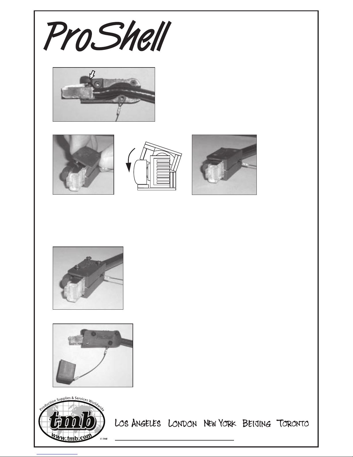
1
2
3
5
4
Insert RJ45 and cable into ProShell housing by
“rolling”, bottom rst, over the small hump until RJ45
“snaps” completely into position. A distinct snap
must be felt to ensure proper alignment.
Prior to inserting cable into ProShell
housing, bend the cable to simulate the
shape of the internal strain relief mold of the
housing.
If installing optional protective cap, place
tether loop on tether post (bottom screw
standoff).
Lay non-logo side of ProShell housing (i.e.
side of housing without “ProShell” logo) on
hard surface with internal section facing up.
Using a small screwdriver, gently pry up the
RJ45 latch-tab 45-50 degrees. (Standard
procedure with RJ45s, as the tab may
compress during assembly.) Caution: Do not
lift too high and risk breaking the tab.
Page 2
R101909
6
7
8
9
www.tmb.com/products/ProShell
Check to see that the latch moves freely.
Check that the optional protective cap tether
loop, if installed, also moves freely and is not
pinched.
Insert three screws. Tighten the two rear screws
rst, then the front screw near the latch. Do not
overtighten, especially the front screw.
“Roll” the logo side of the ProShell housing onto the housing/cable/
thumb lock assembly. Bottom section of housing must contact
assembly rst. When mating the two housing halves, a distinct
“snap” must be felt in order to ensure proper alignment.
Place the ProShell thumb lock tab on
the top front screw standoff.
ASSEMBLY INSTRUCTIONS
 Loading...