

Page 1
ProPlex 0-10V DMX Co nverter DIN Rail
Quick Start Guide
TMB 24/7 Technical Support
US/Canada: +1 818.794.1286
Toll Free: 1 877.862.3833 (877.TMB.DUDE)
UK: +44 (0)20.8574.9739
Toll Free: 0800.652.5418
e-mail: techsupport@tmb.com
v.1.1 rev 070819
Page 2

Introduction
Part Number
PP010VCDIN
Control Channels
4
RDM support
Yes
Operating Voltage
12-24 VDC (Requires external power
supply)
Power Consumption
3 W Max.
Isolation Voltage
3000 V
Output Current
10 mA per output
Output Setting Time
5 msec
Input impedance (Theatre mode)
1 MΩ
Input sink mode current
1 mA
Output short circuit current
60 mA
Output short restoring time
6 sec
DMX step value
40mV / DMX step
Power Input
Phoenix MSTB 2-terminal
Data Input
Phoenix MSTB 3-terminal
Data Thru
Phoenix MSTB 3-terminal
Control Input/Outputs
4x Phoenix MSTB 2-terminal
Operating Temp
-22 °F - 104 °F [-30 °C - +40 °C]
Dimensions (HxWxD)
1.55” x 4.1” x 3.63” [39.5 x 104 x 92.3
mm]
Weight
5.6 oz [159 g]
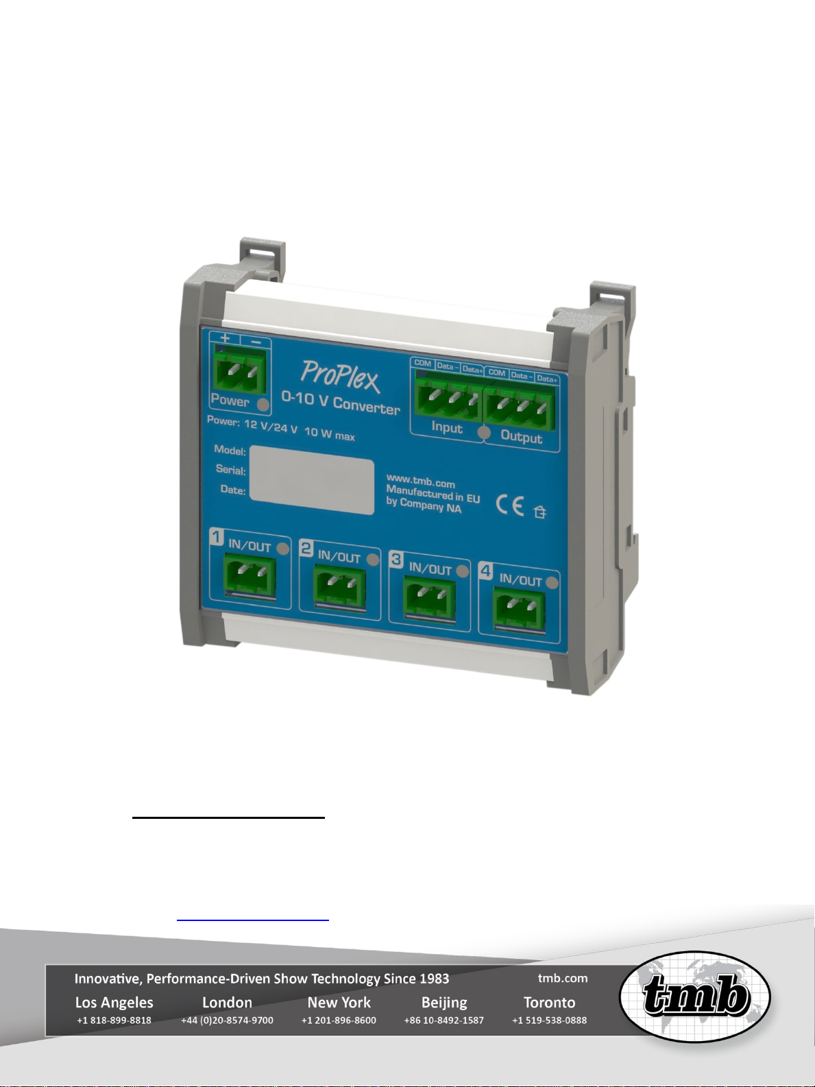
0-10V DMX Converter DIN Rail Mount converts 0-10V to DMX or DMX to 0-10V.
The device has four Input/Output ports and four operational modes: Theatre Out;
Ballast Out; Theatre In; Ballast In. Assign DMX channels, link with analog ports,
select analog modes via RDM.
• Bidirectional! Convert 0-10V to DMX or DMX to 0-10V
• Four operational modes: Theatre Out, Ballast Out, Theatre In, Ballast In
• 4x 0-10V inputs or outputs
• Assign DMX channels, link with analog ports, select analog modes via RDM
• Compatible with ANSI E1.3 (Theatre mode / 0-10V) and IEC Standard
• 60929 Annex E (Ballast mode / sink mode / 1-10V)
• Phoenix MSTB screw terminals for bare-wire, installation flexibility
Technical Data
Page 3
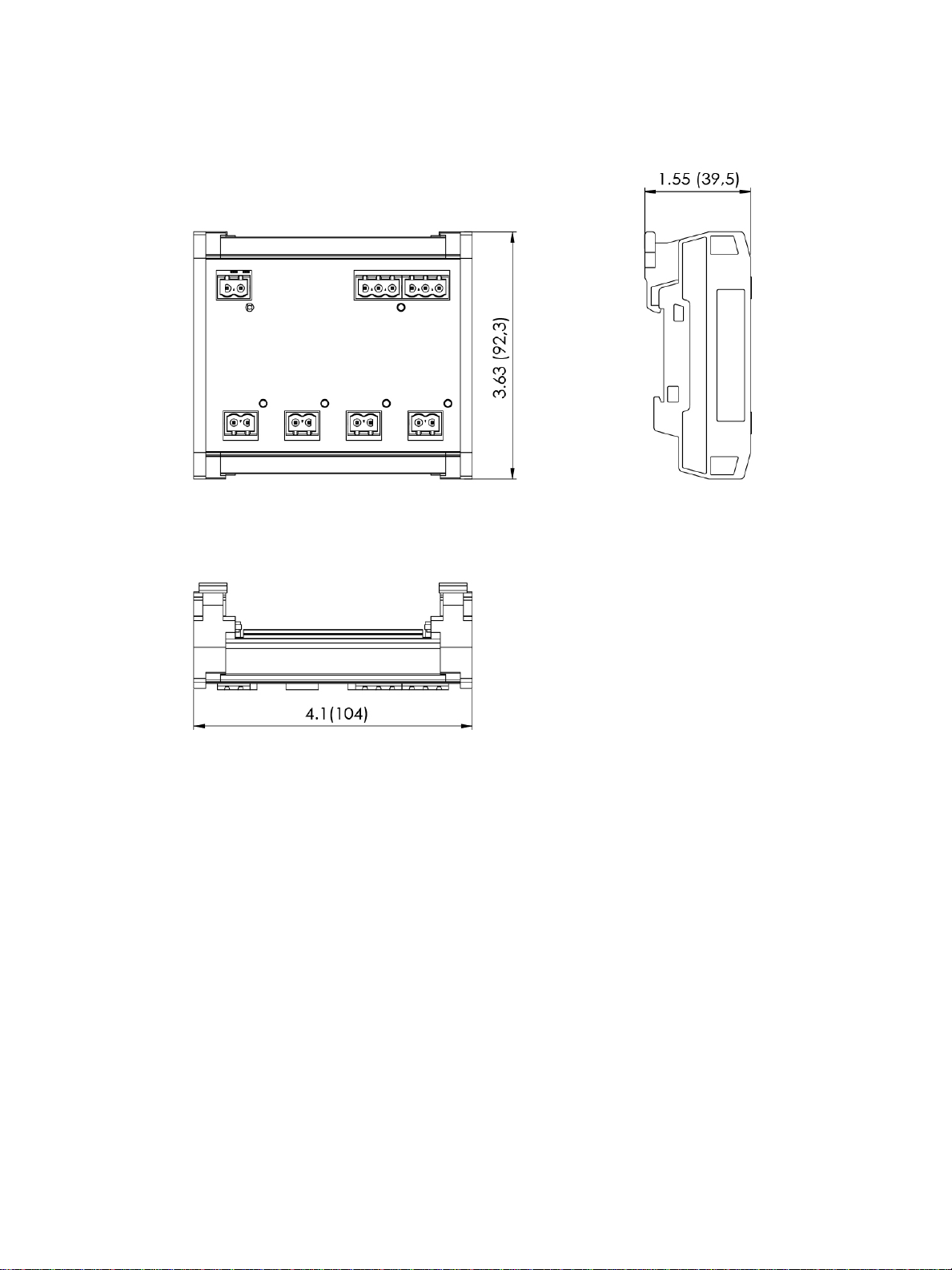
Dimensions
Page 4

Overview
Setup
Connect the DC power (12/24V) to the power input located in the left top corner. The
connector should be wired as follows:
Page 5

Connect the DMX signal input to the DMX input located in the right top corner of the
unit. The connector should be wired as follows:
Connect the DMX signal output to the DMX output located in the right top corner of
the unit. The connector should be wired as follows:
LED Status
The Power LED has two states: ON and OFF
Unit is receiving power.
Unit is not receiving power.
Page 6

DMX data LED has two states: Glowing red and flashing orange.
If there is no DMX signal, the Input LED will glow red. If there is an incoming DMX,
the LED will flash green and orange.
Input/Output LEDs indicate signal level or fault conditions:
Operation
Each mode coverts either DMX to 0-10V or 0-10V to DMX control. 0-10V inputs are
numbered 1-4 at the bottom of the unit and correspond with sequential DMX
addresses depending on the set starting address. DMX starting address can only be
changed via RDM compatible controllers.
For Example:
If the DMX start i ng address is 1, then each 0-10V input/output will correspond with
exactly the same DMX address as follows:
• 0-10V Input/Output #1 corresponds with DMX channel 1
• 0-10V Input/Output #2 corresponds with DMX channel 2
• 0-10V Input/Output #3 corresponds with DMX channel 4
• 0-10V Input/Output #4 corresponds with DMX channel 4
If DMX starting address is 37, then each 0-10V input/output will correspond with the
DMX starting address in sequence:
Page 7

• 0-10V Input/Output #1 corresponds with DMX channel 37
• 0-10V Input/Output #2 corresponds with DMX channel 38
• 0-10V Input/Output #3 corresponds with DMX channel 39
• 0-10V Input/Output #4 corresponds with DMX channel 40
Operational Modes
• Output Theatre (source 0-10V)
o Incoming DMX signal converted to 0-10V current source.
• Output Ballast (sink)
o Incoming DMX signal converted to 0-10V current sink.
• Input Theatre (hi-Z input )
o Incoming 0-10V current source converted to DMX.
• Input Ballast (source current 1 mA/10V)
o Incoming 0-10V current sink converted to DMX.
Current Source and Current Sink
ProPlex 0-10V DMX Converter is an analog lighting control protocol whereby a
control voltage between 0-10V DC produces varying intensity levels in a lighting
fixture.
There are two 0-10V standards that are not compatible with each other:
1) Current Source was originally used for controlling theatrical lighting,
standardized by ANSI E1.3;
2) Current Sink is a method of 0-10V control used mainly in controlling
ballasts, and more recently, LED Drivers. This method is standardized by
IEC Standard 60929 Annex E.
The fundamental difference between the two protocols is where the control voltage is
coming from. Current Source requires the controller to generate or “source” the low
voltage signal. In the case of current sinking, the device under control (ballast, driver
or dimmer) supplies the voltage, which “sinks” through the controller. When
specifying 0-10V controls, you must be certain that both the controller and the
lighting device being controlled utilize the same protocol.
 Loading...