

Page 1
GBS 10-Port Gigabit Switch
USER MANUAL
TMB 24/7 Technical Support
US/Canada: +1 818.794.1286
Toll Free: 1 877.862.3833 (877.TMB.DUDE)
UK: +44 (0)20.8574.9739
Toll Free: 0800.652.5418
e-mail: techsupport@tmb.com
Page 2

TABLE OF CONTENTS
1. INTRODUCTION .................................................................................................................. 3
PRODUCT OVERVIEW ....................................................................................................................................... 3
M
ORE ABOUT PROPLEX GBS 10-PORT ........................................................................................................... 3
U
NPACKING INSTRUCTIONS .............................................................................................................................. 4
P
OWER REQUIREMENTS .................................................................................................................................. 4
S
AFETY INSTRUCTIONS .................................................................................................................................... 4
F
USE REPLACEMENT ....................................................................................................................................... 5
W
IRING ........................................................................................................................................................... 5
P
ANEL FRONT/BACK ........................................................................................................................................ 5
LED
STATUS ................................................................................................................................................... 6
2. CONFIGURATION ................................................................................................................ 7
DATA PORT MODULE DISASSEMBLY ................................................................................................................. 7
C
ONNECTORS ............................................................................................................................................... 10
M
IXED MEDIA PORTS ..................................................................................................................................... 11
D
ATA PORT MODULE ASSEMBLY .................................................................................................................... 12
F
IBER OPTIC PORT INSTALLATION .................................................................................................................. 15
3. APPENDIX ....................................................................................................................... 17
LIMITED WARRANTY ...................................................................................................................................... 17
R
ETURN PROCEDURE .................................................................................................................................... 17
T
ECHNICAL SPECIFICATIONS .......................................................................................................................... 18
Page 3

GBS 10-port user manual version 1.2 090618
- 3 -
INTRODUCTION
PRODUCT OVERVIEW
ProPlex GBS Gigabit Ethernet switches are designed for portable entertainment production amd are part of
the ProPlex Data Distribution range of products for complete touring show data management. Just a few
features include:
• Reconfigurable! Any combination of data port modules can be moved between front and rear panels
for practical gig-specif ic w ir i ng.
•
Built for extreme conditions. Shock-mounted circuitry. Advanced thermal management.
• Fibre option via one or two heavy-duty OpticalCON QUAD connectors. OpticalCON DUO also
available by special order.
• Gigabit Ethernet: 10 ports with tour-grade EtherCON connec tors . Up to 10 tour-gr ade Eth erCO N
connectors or up to 8 EtherCON ports with optional fibre connectivity via 1 or 2 heavy-duty
OpticalCON QUAD connectors.
• PoE and non-PoE versions available
• Compatible with a wide range of entertainment-specific protocols, including sACN, ArtNet,
CobraNet, Dante, ETCNet, Ethersound, MA-Net, and more!
• Variable power input, 90-260 VAC, 50-60 Hz with PowerCON connector
• ProPlex “Blue Box” RackMount, rugged tour-ready enclosure
The rugged ProPlex GBS 10-port is suitable for high-volume, multicast, video, audio, or lighting data
streaming with forwarding rate of 14.88 million Packets per Second (64-byte packets ) and Switc hi ng
Capacity of 20.0 Gigabits per Second. ProPlex GBS supports:
• 4,096 simultaneous VLANs, port-based and 802.1Q tag-based VLANs and MAC-bas ed VL AN
• Internet Group Management Protocol with the ability to limit bandwidth-intensive multicast traffic
• IGMP Querier support to forward multicast traffic
• 802.1d Spanning Tree support
• Fast convergence 802.1w support
• Native IPv6 Internet Protocol support with option to deliver IPv6 multicast packets only to the
required receivers
• Previous version support for IPv4 routing with up to 512 static routes and up to 128 IP interfaces
• Built-in browser-based switch configuration utility
GBS RackMount and DIN Rail models are available with PoE functionality, enabled by default on
ports 1- 8 (PoE+ ports with 124W power budget and 10/100/1000 max.) Ports 9 and 10 does not
support PoE functionality. PoE technology enables Ethernet network cables to function as power
cords. In a PoE enabled network, electrical current flows over CAT5 or higher network data cable
together with normal Ethernet data traffic. No extra AC power cord is needed at the product location,
minimizing the amount of cables needed and/or the inconvenience of installing extra outlets
Note: For Managed Mode access, contact TMB Tech Support
Page 4

GBS 10-port user manual version 1.2 090618
- 4 -
UNPACKING INSTRUCTIONS
Upon receipt of the unit, carefully unpack the carton and check the contents to ensure that all parts are
present and in good condition. Notify the shipper immediately and retain packing material for inspection if
any parts appear to be damaged from shipping or if the carton itself shows signs of mishandling. Sa ve the
carton and all packing materials. In the event that a unit must be returned to the factory, it is important that it
be returned in the original factory box and packing.
POWER REQUIREMENTS
Before powering the unit, make sure the line voltage is within the range of accepted voltages. This unit
accommodates 90-26 0 VAC, 50/60Hz. All units must be powered directly from a switched circuit and cannot
be operated with a rheostat (variable resistor) or dimmer circuit, even if the rheostat or dimmer channel is
used solely for a 0-100% switch.
S
AFETY INSTRUCTIONS
• Keep this User Guide for future reference. If unit is sold to another user, make sure they also receive
this instruction booklet.
• Ensure the unit is connected to proper voltage, and that line voltage is not higher than that stated on the
device.
• Make sure there are no flammable materials close to the unit while oper ati ng.
• Always disconnect from the power source before servicing or fuse replacement. Always use the fuse
specified in this manual..
• Always use a safety cable when hanging unit overhead.
• Maximum ambient temperature (Ta) is 40°C (104°F). Do not operate unit at temperatures above this
rating.
• In the event of a serious operating problem, stop using the unit immediately. Repairs must be carried
out by trained, authroized personnel. Conact the nearest authorized technical assistance center. Only
OEM spare parts should be used.
• Do not connect the device to a dimmer pack.
• Make sure power cord is never crimped or damaged.
• Never disconnect power cord by pulling or tugging on the cord.
Please read these instructions carefully. This user guide
contains important information about the installation, us age
and maintenance of this product.
Page 5
GBS 10-port user manual version 1.2 090618
- 5 -
FUSE REPLACEMENT
The GBS 10-port RackMount uses a 1.5A, 250V barrel fuse, 5x20mm (0.2x0.8 in.).
To replace fuse:
1. With a screwdriver, turn the fuse cap counter-clockwise to remove fuse cap with fuse.
2. Replace fuse attached to fuse cap.
3. Reinsert fuse cap with new fuse and tighten clockwise.
W
IRING
Connect the 90-260 VAC (50- 60 Hz) power to the power input (PowerCON) at the back of the unit.
P
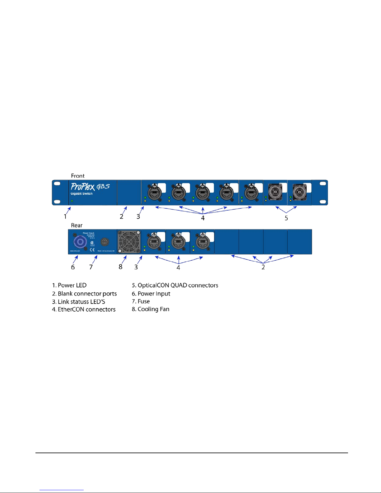
ANELS – FRONT / BACK
Page 6
GBS 10-port user manual version 1.2 090618
- 6 -
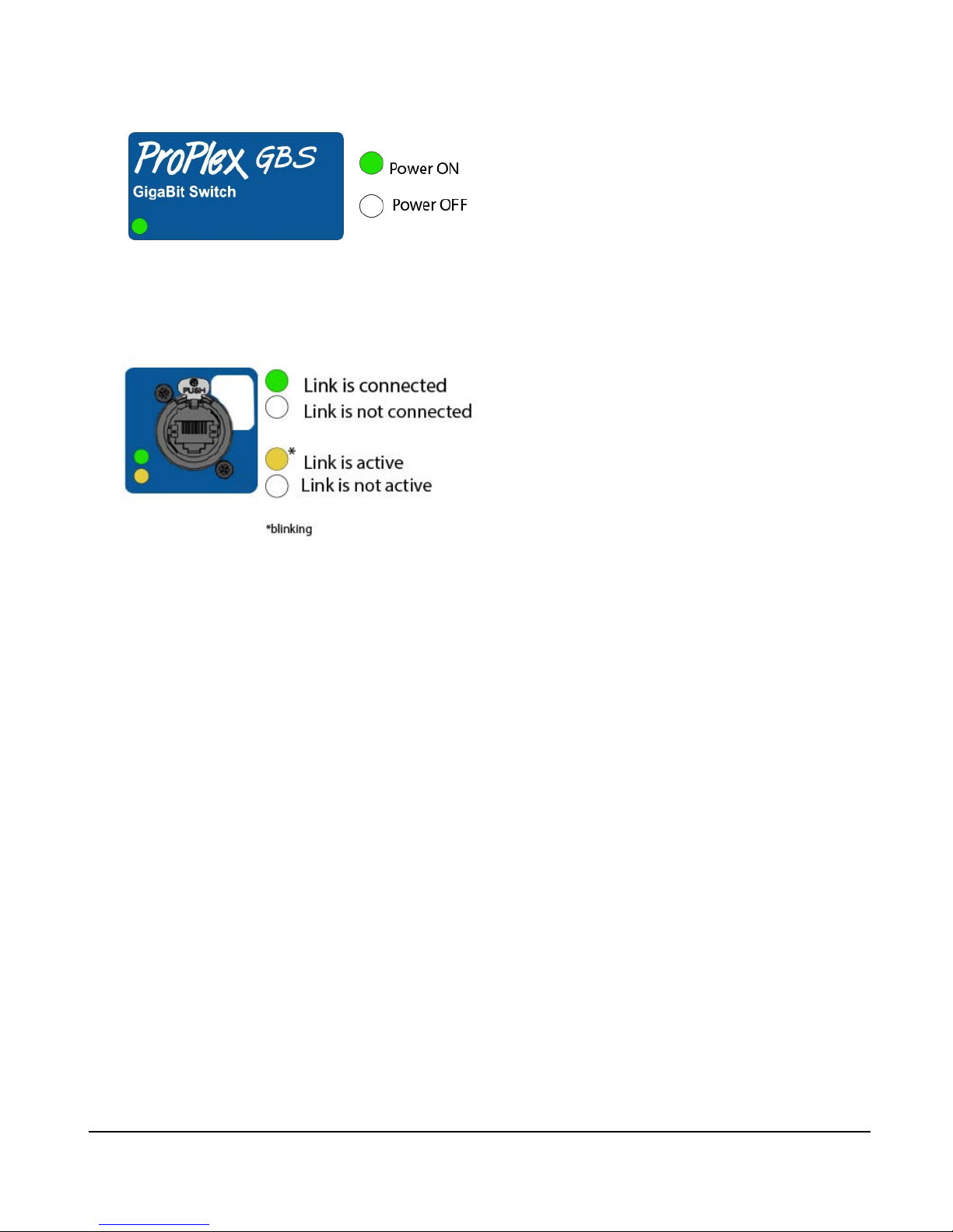
LED STATUS
The Power LED has two states: ON and OFF
• ON: Unit is receiving power
• OFF: Unit is not recei v ing po wer
The Link Connection LED has two states:
• Glowing green: There is a link connection
• OFF: There is no link connection
The Link Activity LED has two states:
• Blinking yellow : There is activ it y on the link
• OFF: There is no activity on the link
Page 7

GBS 10-port user manual version 1.2 090618
- 7 -
CONFIGURATION
DATA PORT MODULE DISASSEMBLY
To meet specific wiring needs of any entertainment application, it is possible to move data port modules
between the front and rear of the unit in any combination, giving more freedom when creating a multicast
network.
1. Using a Phillips #2 screwdriver, remove all 12 screws from the unit’s case lid.
2. Once the lid is removed, the grounding cable can be undone with 9/32-inch (7mm) wrench. (This step is
not obligatory as it is possible to work on the GBS switch without disconnecting the grounding cable.)
Step 2
Step 1
Page 8

GBS 10-port user manual version 1.2 090618
- 8 -
3. To unscrew a port housing, two Philips screws must be undone. One on the top, the other on the bottom
side of the ProPlex GBS switch. Remove the screws from ports which you want to swap places. Take
out the blank port housing and set it aside
4. The desired connector housing can be released from its mounting.
5. Unfasten twist-locks and cable management clips that can be undone and refaste ned b y hand.
Step 3
Step 4
Step 5
Page 9

GBS 10-port user manual version 1.2 090618
- 9 -
6 When the clips are unfastened, the connector can be disconnected from the port. To do so, push down
on the RJ-45 connector clip and slide it out. To disconnect the 3-pin LED connector, pull firmly with
your fingertips on both sides until the connector slides out.
7. Once the tail is disconnected from the main switch, slide it out of the unit.
Step 6
Step 7
Page 10

GBS 10-port user manual version 1.2 090618
- 10 -
CONNECTORS
Each port panel is fed by a 3-pin LED conn ec tor, ind ic atin g network activity, as well as a CAT5e RJ45 or
fibre jumper that connects to the EtherCon or OpticalCon QUAD connector on that panel. These cables are
bundled together inside a TechFlex
®
sleeve.
Page 11

GBS 10-port user manual version 1.2 090618
- 11 -
MIXED MEDIA PORTS
Fig. 1
Note! Ports 9 and 10 on the GBS switch are mixed media ports and can function as ether Ethernet or Fibre
Optic Ports. It is important to remember, that each port can only manage one data stream at a time.
Although it is possible to physically plug both fibre and Ethernet into the mixed media ports, do not do so,
because the different streams cannot operate on the same internal port.
Fig. 2 Fig. 3
Figures 2 and 3 illustrate that mixed media ports can function as either Ethernet or fibre optic ports.
Important: Do not plug in both Ethernet and fibre optic cables at the same time.
Page 12

GBS 10-port user manual version 1.2 090618
- 12 -
DATA PORT MODULE ASSEMBLY
1. The connector must be placed in to the new location from which the blank port housing was removed
making sure, that the white marking on the housing is towards the upper part of the unit and that the
port housing is seated firmly. Route the cable back into the unit to a free port.
Step 1
2. Connect the RJ-45 connector, making sure the clip is
facing upwards. Press it down and in until it clicks,
ensuring that the connector is in place.
Step 2
Page 13

GBS 10-port user manual version 1.2 090618
- 13 -
3. Connect the 3-pin LED connector by pressing it in firmly with
fingertips at both sides of the connector.
4. Once the connectors are in, situate the cable back into the
cable management system with twist-locks and cable
management ties, making sure that the cable is not stressed
or cramped on either end.
Step 3
Step 4
Page 14

GBS 10-port user manual version 1.2 090618
- 14 -
5. Insert the blank port housing into the empty slot.
6. Replace the screws on both panels, top and bottom.
7. Screw the grounding cable back to the unit if disconnected from the case lid. If not disconnected, put
the case lid back onto the unit and fasten it securely.
Step 5
Page 15

GBS 10-port user manual version 1.2 090618
- 15 -
FIBER OPTIC PORT INSTALLATION
If an OpticalCON QUAD connector is installed for the first time, you will need an SFP module to be inserted
in the fibre optic port to connect the LC Duplex connector. ProPlex GBS 1U models that come with
OpticalCON QUAD connectors as standard are equipped with a MikroTI K 1.25G SFP transc ei ver wit h a
850nm Dual LC connector, for up to 550 meter Multi Mode fibre connection, with DDM (Fig. 4). The adapter
can be exchanged if needed.
1. To install the SFP module, slide the SFP with the label facing upwards into the vacant slot.
2. When it is fully engaged, the black-handled lever must be pulled upwards to lock the SFP in place.
Fig. 4
Step 1
Step 2
Page 16

GBS 10-port user manual version 1.2 090618
- 16 -
3. Press the fibre cable into the SFP until the
clicking sound is heard. This means that the
Duplex connector is in place.
4.
Connect the 3-pin LED c onnec tor b y push ing it
with sfingertips until it clicks into place.
Note:
To undo the Duplex connector, push down
on the plastic clip and pull the connector out.
To disconnect the three pin LED connector, pull
firmly with your fingertips on both sides and
connector slides out.
Step 3 and 4
Page 17

GBS 10-port user manual version 1.2 090618
- 17 -
APPENDIX
L
IMITED WARRANTY
ProPlex Data Distribution Devices are warranted by TMB against defective materials or workmanship for a
period of two (2) years from the date of original sale by TMB.
TMB’s warranty shall be restricted to the repair or replacement of any part that proves to be defective and for
which a claim is submitted to TMB before the expiration of the applicable warranty periods.
This Limited Warranty is void if the defects of the Product are the result of:
• Opening the casing, repair, or adjustment by anyone other than TMB or persons specifically authorized
by TMB
• Accident, physical abuse, mishandling, or misapplication of the product.
• Damage due to lightning, earthquake, flood, terrorism, war, or act of God.
TMB will not assume responsibility for any labor expended, or materials used, to replace and/or repair the
Product without TMB’s prior written authorization. Any repair of the Product in the field, and any associated
labor charges, must be authorized in advance by TMB. Freight costs on warranty repairs are split 50/50:
Customer pays to ship defective product to TMB; TMB pays to ship repaired product, ground freight, back to
Customer. This warranty does not cover consequential damages or costs of any kind.
A Return Merchandise Authorization (RMA) Number must be obtained from TMB prior to return of any
defective merchandise for warranty or non-warranty repair. For all repairs please contact TMB Tech Support
Repair using the contact information below or email TechSupportRepairNA@tmb.com.
US UK
527 Park Ave. 21 Armstrong Way
San Fernando, CA 91340 Southall, UB2 4SD England
Tel: +1 818.899.8818 Tel: +44 (0)20.8574.9700
Fax: +1 818.899.8813 Fax: +44 (0)20.8574.9701
tmb-info@tmb.com tmb-info@tmb.com
www.tmb.com www.tmb.com
R
ETURN PROCEDURE
Please send returned merchandise prepa id and in the original packing. Freight call tags will not be issued
for shipping the product to TMB, but TMB will pay the freight for return to the customer. Clearly label
package with a Return Merchandise Authorization Number (RMA #). Products returned without an RMA #
will delay service. Please contact TMB and request an RMA # prior to shipping the unit. Be prepared to
provide the model number, ser ial num ber , and a brief description of the cause for the return. Be sure to
properly pack the unit; any shipping damage resulting from inadequate packaging is the customer’s
responsibility. TMB reserves the right to use its own discretion to repair or replace product(s). Proper UPS
packing or double-boxing will better ensure product integrity when shipped.
Note: If you are given an RMA #, please include the following information on a piece of paper inside
the box:
1) Your name
2) Your address
3) Your phone number
4) The RMA #
5) A brief description of the s ymptoms
Page 18

GBS 10-port user manual version 1.2 090618
- 18 -
PROPLEX GBS 10-PORT – TECHNICAL SPECIFICATIONS
Power input
90-260VAC, 50-60Hz with PowerCON connector
Operating temperature:
32° to 104° F (0°to 40°C)
Number of ports
10
Forwarding rate
14.88 Million of Packets per Second (mpps) (64-byte
packets)
Switching Capacit y
20.0 Gigabits per Second (Gbps)
IPv4 routing
Up to 512 static routes and up to 128 IP interfaces
Pv6 QoS
Prioritize IPv6 packets in hardware
Port grouping
Support for IEEE 802.3ad Link Aggregation Control
Protocol (LACP)
VLAN
Up to 4096 VLANs simultaneously
Buffer memory
8 MB
Jumbo Frames
Up to 9K (9216) bytes
Priority levels
4 hardware queues
Dimensions (H x W x D)
1.72 x 19.0 x 18.69 in (43,8 x 482,6 x 474,7 mm)
Weight
14 lbs (6,35 kg)
 Loading...