

Page 1

Revised: 24 August 2011
Operating Manual
Page 2

ProFan Operating Manual
2
TABLE OF CONTENTS
1. BEFORE YOU BEGIN....................................................... 3
ProFan Overview 3
Unpacking Instructions 3
Exploded Views 4
2. SAFETY INSTRUCTIONS................................................. 5
3. MOUNTING....................................................................... 6
Mounting Options 6
Attaching the Yoke Assembly 7
Overhead Rigging 8
Support Stand 8
4. REMOTE CONTROL........................................................ 9
Basics of DMX Control 9
DMX Data Cable 9
Cable Connectors 10
DMX Termination 10
3-Pin to 5-Pin Conversion 11
5. OPERATING INSTRUCTIONS......................................... 12
Back Pack Overview 12
Connecting the Back Pack Controller 13
DMX Mode 15
Manual Mode 16
Master/Slave Operation 17
Using ProFan with a Smoke Machine 18
6. TROUBLESHOOTING AND MAINTENANCE................. 19
Troubleshooting 19
Replacing the Fuse 20
Cleaning 20
7. APPENDIX....................................................................... 21
Limited Warranty 21
Technical Specifications 22
Contact Information 23
Page 3

ProFan Operating Manual
3
1. BEFORE YOU BEGIN
ProFan Overview
ProFan is a professional DMX-controlled fan capable of producing
high velocity air current. It can operate from 100 to 240VAC.
Multiple ProFans can also slave together to increase air flow or to
achieve complex flow patterns for special effects. The ProFan is
designed to mount upon a stand or (using ProBurger Accessory
clamps or couplers) suspend from a truss or other suitable support.
The external Back Pack controller allows DMX or manual control.
Manual control, using the onboard slide fader, adjusts fan speed
from zero to full.
The ProFan housing is molded lightweight polymer; the venting
area is protected with rugged tubular steel. The 11" one-piece
three-blade vane and spiral front grille creates a focused wind
effect.
ProFan applications range from general wind effects to blowing
smoke, haze, bubbles and confetti with programmable effect and
distance. Additionally, air circulation, ventilation and ambient
cooling can be equally controlled with repeatable characteristics
and effects.
Unpacking Instructions
Immediately upon receiving the fixture, carefully unpack the carton
and check the contents to ensure that all parts are present (see
exploded view) and have been received in good condition. Notify
the shipper immediately and retain packing material for inspection
if any parts appear damaged from shipping or the carton itself
shows signs of mishandling.
Page 4
ProFan Operating Manual
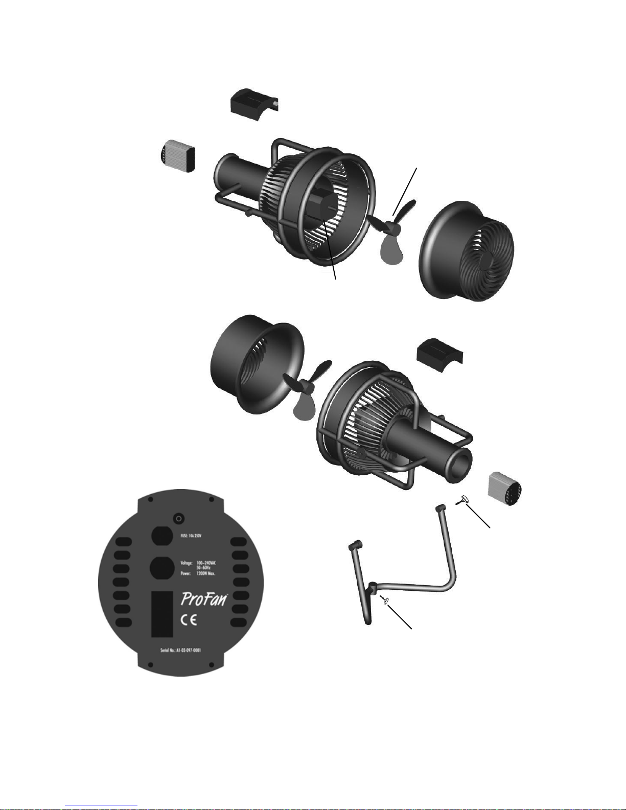
4
Back Pack Controller
Power
Supply
Motor
Grille
Body
Yoke
Back Panel Detail
Knob
Blade
Knob
Page 5
ProFan Operating Manual
5
2. SAFETY INSTRUCTIONS
Preventing Fire and Electric Shock
Always ground (earth) the machine electrically.
ProFan has a built-in speed control. Do not connect ProFan to
any external solid-state speed control device or dimmer circuit.
Disconnect the machine from power before removing any
components or servicing, and when not in use.
Moisture can cause dangerous electrical faults. Do not aim fog
output at electrical connections or devices.
Do not expose this machine to excess moisture. ProFan is
NOT waterproof.
Do not spill fluid over the machine. In the event of a fluid spill,
disconnect the machine from power and clean with a damp
cloth. If fluid is spilled onto electrical components, contact TMB.
Do not dismantle or attempt to repair a faulty machine. Refer
all service to TMB.
Do not operate the machine if the power cable or connector is
damaged. A damaged cable or connector must be replaced
with a new item, available from TMB.
Do not operate the machine with damaged, deformed or
missing parts.
Preventing Injuries
Never allow any object or part of the body to enter the path of
the fan blades. Ensure that clothing, cables or other items
cannot be sucked into the fan.
Disconnect power before removing cover or grille. Do not
operate unless all covers and grilles are installed and securely
fastened.
ProFan is designed to be used by professionals,
and is NOT intended for household use. Improper
use can cause severe injury due to electrical or
mechanical hazards.
Page 6
ProFan Operating Manual
6
Ensure that any supporting structure or surface can hold at
least 10 times the weight of all installed devices.
Use approved secondary attachment when possible, such as a
safety cable.
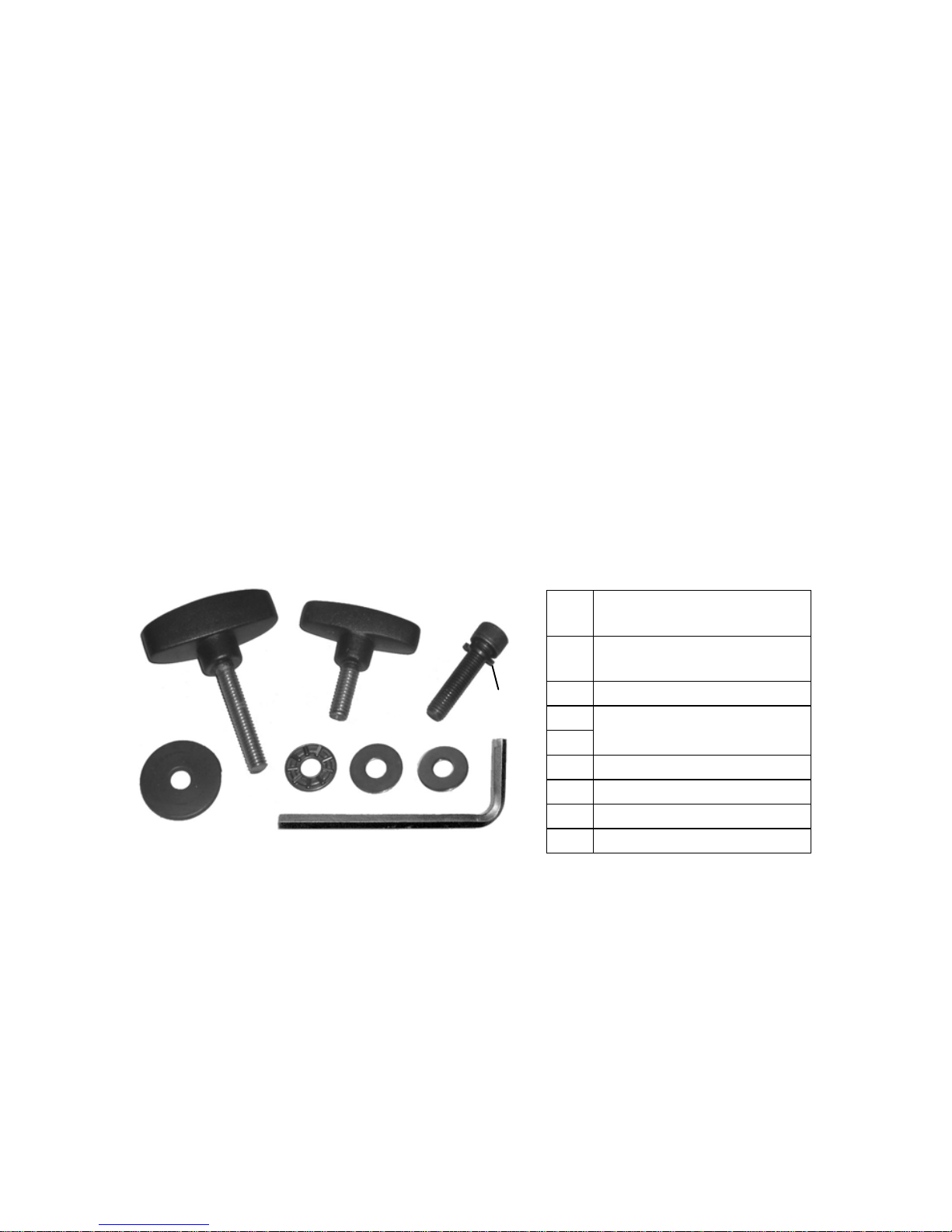
3. MOUNTING
Mounting Options
ProFan may be suspended, mounted on a suitable stand, or stood
alone on its own steel yoke.
As delivered, the ProFan is ready for stand alone use. Included
with the ProFan is a yoke assembly for mating the unit to a floor
stand or suspension clamp. The yoke assembly easily attaches to
the ProFan using the provided fasteners and wrench.
A1 Small head, short
shank, T-Handle Knob
B1
Large Head, long
shank, T-Handle Knob
B2 Thrust Washer
B3
B4
Flat Washer
B5 Aluminum Bushing
C1 Allen Bolt
C2 Split Washer
C3 Allen Wrench
B1
A1
C1
C2
C3
B2
B3
B4
B5
Page 7
ProFan Operating Manual
7
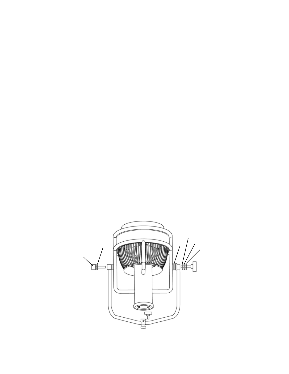
Attaching the Yoke Assembly
1. Place the ProFan face down upon its front grille with the hinge
barrel side on the left and the hinge flat side on the right.
2. Place Item B3 flat washer upon the shank of Item B1 T-Handle,
followed by Item B2 thrust washer and Item B4 flat washer.
3. Place the yoke bracket into position. Insert the shank of Item
B1 T-Handle through the flat face hinge until the shank just
protrudes from the flat face.
4. Insert Item B5 aluminum bushing between the ProFan
housing’s tubular bracket and the yoke assembly hinge’s flat
face.
5. Rotate the T-Handle clockwise until the T-Handle has
threaded into the ProFan tubular housing bracket. Do not
tighten completely at this point.
6. Place Item C2 split washer onto Item C1 Allen bolt. Place the
Allen bolt through the barrel portion of the ProFan hinge and
rotate the bolt until it threads into place.
7. Tighten the Allen bolt and the T-Handle until the yoke
assembly is fixed and not easily moved.
8. At this point the ProFan is ready for mating with a stand or
clamp. Grip the fan by its tubular housing brackets when lifting
or mounting to avoid pinching hands or fingers.
B1
A1
C1
C2
B2
B3
B4
B5
Page 8

ProFan Operating Manual
8
Overhead Rigging
Recommended ProBurger rigging clamps:
1. PRBHC3/8 or PRBHC1/2 Half Couplers
2. PRBSNC1/2 Snap Coupler.
It is recommended that any structure used to support the unit can
support at least 10 times the total weight of all installed fixtures,
clamps, auxiliary equipment, etc.
1. Check that all rigging clamps are undamaged and can support
at least 10 times the weight of the unit.
2. Clamp the fan to truss or similar support.
3. Loosen the swivel locks and tilt the fan to the desired angle.
Turn the swivel locks clockwise to tighten. Make sure that fan,
hardware, and safety attachment are secure before applying
power.
Support Stand
A professional stand, rated to support a weight greater than the
unit, must be used to support the ProFan. TMB ProStands,
supplied with a PRXTVMP adapter, provide a reliable floorstanding solution
Page 9

ProFan Operating Manual
9
4. REMOTE CONTROL
Basics of DMX Control
There are 512 channels in a DMX-512 connection. Channels may
be assigned in any manner. A fixture capable of receiving DMX512 will require one or a number of sequential channels. The user
must assign a starting address on the fixture that indicates the first
channel reserved in the lighting console. There are many different
types of DMX controllable fixtures and they all may vary in the
total number of channels required. Choosing a start address
should be planned in advance. Channels should never overlap. If
they do, this will result in erratic operation of the fixtures whose
starting addresses are set incorrectly. You can however, control
multiple fixtures of the same type using the same starting address
as long as the intended result is that of unison movement or
operation. In other words, the fixtures will be slaved together and
all will respond in the same way.
DMX fixtures are often designed to receive and transmit data
through a DMX daisy-chain. A DMX daisy-chain is where the DMX
THRU of one fixture connects to the DMX IN of the next fixture.
The order in which the fixtures are connected is not important and
has no effect on how a lighting console communicates to each
fixture. Use an order that provides for the easiest and most direct
cabling. Connect fixtures using shielded two-conductor twisted
pair cable with 5-pin XLR male to female connectors. The
shield/ground is pin 1, while pin 2 is Data Negative (D-) and pin 3
is Data positive (D+). Pins 4 and 5 are not used according to the
DMX-512 standard.
DMX Data Cable
Use a ProPlex® PC222P, PC224P, or equivalent cable which
meets the specifications for EIA RS-485 applications. Standard
microphone cables cannot transmit DMX data reliably over long
distances. The cable should have the following characteristics:
Page 10

ProFan Operating Manual
10
Minimum 2-conductor twisted pair plus a shield
Maximum capacitance between conductors – 22 pF/ft.
Maximum capacitance between conductor and shield – 41 pF/ft.
Maximum resistance of 14.5 ohms / 1000 ft.
Characteristic impedance of 80 – 110 ohms
Cable Connectors
Cabling must have a male XLR connector on one end and a
female XLR connector on the other end.
DMX connector configuration
The maximum recommended DMX data link distance between
fixtures is 300 meters (984 ft.)
DMX Termination
Use of a DMX terminator is strongly recommended for the last
fixture in a DMX chain. Comprised of a 120Ω resistor across XLR
pins 2 and 3, a terminator prevents electrical reflections from
traveling back down the signal chain and corrupting the DMX data
stream. External XLR terminators such as the ProPlex “Arnold”
are available for such use.
Page 11

ProFan Operating Manual
11
CAUTION: Another consideration to prevent the corruption
of DMX data is to not allow contact between the common (pin
1) of a DMX cable and the fixture’s chassis ground.
Grounding the common can cause a ground loop, and your
fixture may perform erratically.
Test cables and terminators with a continuity tester to verify
correct polarity and to make sure the pins are not grounded
or shorted to the shield or each other.
3-Pin to 5-Pin Conversion Chart
If you use a console with a 3-pin DMX output connector, you will
need to use a 3-pin to 5-pin adapter. The chart below details a
proper conversion:
3-Pin Male
(Input)
5-Pin Male
(Output)
Purpose
Pin 1 Pin 1 Ground / Shield
Pin 2 Pin 2 Data ( - ) signal
Pin 3 Pin 3 Data ( + ) signal
Pin 4 Not Used
Pin 5 Not Used
Page 12

ProFan Operating Manual
12
5. OPERATING INSTRUCTIONS
Back Pack Overview
XLR 3-pin male
connector to ProFan
DMX/MANUAL
Mode switch
LCD Display
Button:
1. Hold down and slide
fader to set DMX
address in DMX
Mode
2. Press to bump to full
speed in Manual
Mode
Slide Fader Control:
1. Fan Speed Control in
Manual Mode
2. DMX Address Setting in
DMX Mode
DMX512 input &
output XLR 5-pin
connectors
Input
Output
Page 13

ProFan Operating Manual
13
Connecting the Back Pack Controller
With rear fan power switch in OFF position:
Connect the integral male XLR on the Back Pack directly to the
integral female XLR on the fan body. If desired, the Back Pack
can be removed and connected using a standard 3-pin XLR
microphone cable up to 60 ft / 20 m in length.
Attaching the Back Pack to the Fan Housing
The Back Pack is secured to the fan housing by: 1) two snap-in
clips; 2) an internal magnet; 3) the XLR connection.
Prior to connecting the Back Pack to the integral female XLR on
the fan body, notice that two flat slots exist on the top and bottom
of the Back Pack housing. These flat slots mate with the mounting
bracket fixed to the top of the fan housing.
Page 14

ProFan Operating Manual
14
Place the Back Pack with the sliding fader to the left. Push the
Back Pack forward to mate with the integral female XLR while
gently pressing the Back Pack against the fan body. While
inserting the Back Pack onto the integral female XLR, ensure it
aligns with the slot in top face of the Back Pack. Once fully
connected to the integral female XLR, the bottom edge of the
mounting bracket will snap into place fixing the bottom of the Back
Pack by locating into the bottom housing slot.
CAUTION: Double-check that the Back Pack is securely fixed
to the fan housing prior to use.
Note: Ensure the ProFan is pointed in a direction where
considerable wind will not cause a disturbance or any safety
issues.
Turn ProFan on using rear Power switch.
Page 15

ProFan Operating Manual
15
DMX Mode
When the recessed switch on the Back Pack is switched to "DMX",
the display will indicate that the unit is in DMX Mode and will
display the current address of the ProFan. If no incoming DMX
signal is detected, the display will then read "No DMX Found".
To change the address of the unit, press and hold the Full Speed
button while adjusting the fader. With the fader moved all the way
up, the address will change to 512. With the fader moved all the
way down, the address will change to 1. Anywhere in between will
change the address proportionally between those values. To store
the new address, simply release the button.
Page 16

ProFan Operating Manual
16
Manual Mode
When the recessed switch on the Back Pack is switched to
"MANUAL", the display will indicate that the unit is in Manual
Mode. The display will also indicate the current speed of the fan,
based on the position of the fader and whether the Full Speed
button is depressed.
In this mode, a Back Pack controller also acts as a master
controller for up to nine ProFans slaved to it via the DMX OUT
connector. See Master/Slave Operation for details.
Page 17

ProFan Operating Manual
17
Master/Slave Operation
Up to nine ProFans can be locally controlled by one Back Pack
using a DMX data link. To link multiple ProFans, use 5-pin XLR
DMX cables between each pair of fans, as well as female and
male ProPlex "Arnold" DMX terminators on the first and last
ProFans in the chain respectively. Arnolds are wired per the ESTA
DMX512A specification and are available pre-wired from TMB.
Connect each controller to each fan via the XLR 3-pin line female
connector. Connect the 5-pin female Arnold to the 5-pin XLR male
connector on the "master" (i.e. first) ProFan Back Back controller.
Use 5-pin XLR cables to connect the master ProFan output to the
next "slave" ProFan input. Continue connecting ProFans output to
input as needed, up to nine units total. Connect the 5-pin male
DMX terminator to the DMX output of the last ProFan in the chain
Set the mode switch of the master controller to "MANUAL", and
set all the slave controllers to "DMX" at address 001.
Page 18

ProFan Operating Manual
18
Using ProFan with a Smoke Machine
When using ProFan with smoke, fog or hazer machines, place the
fan behind the machines as illustrated below. Do not place the fan
in front of the machine. This will cause residue build-up on the fan
blades and degrade the quality of the smoke, fog, or haze.
.
Correct ProFan placement
behind or to the side of
fogger/hazer
Incorrect
ProFan placement
in front of fogger/hazer
Page 19

ProFan Operating Manual
19
6. TROUBLESHOOTING AND MAINTENANCE
Troubleshooting
Problem Symptom/Cause Suggested Remedy
Display says "No
DMX Found"
Connect DMX
Incorrect DMX
address
Press button and move
fader until correct
address appears
Power is
supplied, but fan
does not operate
via DMX
In Manual Mode
Switch control switch to
DMX mode
No Power
Check power supply and
connection
Fuse blown
Replace fuse with one of
same type and rating
Back Pack
display is blank
Back Pack not
connected
Check connection
Reduced airflow Low voltage supply Check AC supply
Page 20

ProFan Operating Manual
20
Cleaning
Clean the outside of the fan with a damp cloth only. Do not use
solvents. Periodic cleaning of the fan blades and grilles is
necessary to maintain peak performance. Cleaning frequency
depends on the operating environment. Inspect the fan regularly
for dust and smoke residue buildup. Clean as soon as there is
significant dirt buildup on fan blades or if airflow through grilles
becomes restricted. Use a soft brush and vacuum to clean grilles
and fan blades.
Cleaning Steps:
1. Disconnect power
2. Remove the screws to clean the housing and blades
3. After cleaning, make sure that screws are securely tightened
Replacing the Fuse
The fuse can be replaced if necessary.
1. Turn the fuse knob counter-clockwise
2. Replace fuse
3. Turn fuse knob clockwise
Page 21

ProFan Operating Manual
21
7. APPENDIX
Limited Warranty
ProFan products are warranted against defective materials or
workmanship for a period of 12 months from the date of shipment.
Parts and components that are not the product of the Seller (TMB)
shall be subject only to the terms of any warranty that may be
extended by the original manufacturer. Seller’s warranty shall be
restricted to the repair or replacement of any part that proved to
be defective and for which a claim is submitted to the Seller before
the expiration of the applicable warranty periods.
This warranty shall not apply to any defect arising from accident,
misuse or improper or unauthorized adjustment or repair. No
warranty is given with respect to color media or lamps, or with
respect to normal wear and tear.
Any claim for defective merchandise, imperfect manufacture,
shortage in count, or for any other defect known by the Customer
to be existing at time of delivery is waived by the Customer unless
made in writing within 30 days after delivery.
All warranty parts will be charged to the customer until faulty parts
(or product) are returned to TMB for valuation. These parts must
be returned within 30 days of receipt or warranty is void and
parts/shipping become billable items.
Seller will not assume any responsibility for any labor expended or
materials used to replace and/or repair any equipment without
Seller’s prior written authorization. Any labor charges for repairing
or replacing equipment in the field will be negotiated only between
the Seller and general contractor. Freight terms on warranty
repairs are FOB Seller’s warehouse or factory. If warranty parts
and/or repairs are required, Seller agrees to pay destination
ground freight charges on the aforementioned items leaving the
Seller’s facility.
Page 22

ProFan Operating Manual
22
Technical Specifications
Width 19” (480 cm)
Height 22” (560 cm)
Depth 18” (460 mm)
Weight 27.6 lbs (12.5 kg)
Mounting Adjustable swivel yoke
PHYSICAL
Color Black
Nominal voltage 100-240VAC, 50-60Hz
ELECTRICAL
Maximum power
consumption
1200W
Air Volume 1,700 cubic meters/hr
Wind Speed 60 km/hr
RPM 0 to 3,500 variable
PERFORMANCE
Acceleration Zero to full within 2 sec.
Protocol DMX-512A in/out
Control Modes DMX and Manual
Electrical connection
to fan housing
3-pin XLR male
DMX data in 5-pin XLR male
DMX data out 5-pin XLR female
1
Shield/Groun
d
2 Data (-)
3 Data (+)
4 -
BACK PACK
CONTROLLER
DMX XLR pinout
5 -
Page 23

ProFan Operating Manual
23
Contact Information
TMB
US Phone: +1 818.899.8818
UK Phone: +44 (0)20.8574.9700
e-mail: tmb-info@tmb.com
web: www.tmb.com
24/7 Technical Support
US/Canada: +1 877.TMB.DUDE (+1 877.862.3833)
UK: +44 (0)800.652.5418
International: +1 818.794.1286
e-mail: techsupport@tmb.com
19" (480mm) 18" (460mm)
22" (560mm)
Page 24

ProFan Operating Manual
24
 Loading...