

Page 1

MUELLER
®
BAKERY CHILLER
MODELS PMC 40/50 AND PMC 70/120
INSTRUCTIONS FOR
INSTALLATION • OPERATION
Part No. 9842311
Effective February 23, 1999
Revised May 7, 2009
®
REFRIGERATION PRODUCTS
Page 2

BAKERY CHILLER MODELS PMC 40/50 AND PMC 70/120
INSTRUCTIONS FOR INSTALLATION AND OPERATION
Section 1.0 - Bakery Chiller Introduction
1.1 Introduction . . . . . . . . . . . . . . . . . . . . . . . . . . . . . . . . . . . . . . . . . . . . . . . . . . . . . . . . . . . . . . . . . . . .1
1.2 Mueller Bakery Chiller Evaporator Assembly . . . . . . . . . . . . . . . . . . . . . . . . . . . . . . . . . . . . . . . . . . . . .1
1.3 Dimensions and Weight . . . . . . . . . . . . . . . . . . . . . . . . . . . . . . . . . . . . . . . . . . . . . . . . . . . . . . . . . . . .1
1.4 Description of the Equipment . . . . . . . . . . . . . . . . . . . . . . . . . . . . . . . . . . . . . . . . . . . . . . . . . . . . . . .1
1.5 Refrigeration Components . . . . . . . . . . . . . . . . . . . . . . . . . . . . . . . . . . . . . . . . . . . . . . . . . . . . . . . . . .2
1.6 Liquid Solution Flow Components . . . . . . . . . . . . . . . . . . . . . . . . . . . . . . . . . . . . . . . . . . . . . . . . . . . .2
1.7 Electrical Components . . . . . . . . . . . . . . . . . . . . . . . . . . . . . . . . . . . . . . . . . . . . . . . . . . . . . . . . . . . . .2
Section 2.0 - Installation
2.1 Inspection . . . . . . . . . . . . . . . . . . . . . . . . . . . . . . . . . . . . . . . . . . . . . . . . . . . . . . . . . . . . . . . . . . . . . .3
2.2 Safety . . . . . . . . . . . . . . . . . . . . . . . . . . . . . . . . . . . . . . . . . . . . . . . . . . . . . . . . . . . . . . . . . . . . . . . . .3
2.3 Location . . . . . . . . . . . . . . . . . . . . . . . . . . . . . . . . . . . . . . . . . . . . . . . . . . . . . . . . . . . . . . . . . . . . . . .3
2.4 Chilled Water Piping . . . . . . . . . . . . . . . . . . . . . . . . . . . . . . . . . . . . . . . . . . . . . . . . . . . . . . . . . . . . . .3
2.5 Refrigeration Unit Installation . . . . . . . . . . . . . . . . . . . . . . . . . . . . . . . . . . . . . . . . . . . . . . . . . . . . . . . .4
Section 3.0 - First Time Start-Up and Cleaning the System
3.1 First Time Start-Up and Cleaning Procedure . . . . . . . . . . . . . . . . . . . . . . . . . . . . . . . . . . . . . . . . . . . . .5
3.2 Filling the System . . . . . . . . . . . . . . . . . . . . . . . . . . . . . . . . . . . . . . . . . . . . . . . . . . . . . . . . . . . . . . . .5
Section 4.0 - Programming and Troubleshooting
4.1 Power On Sequence of Operation . . . . . . . . . . . . . . . . . . . . . . . . . . . . . . . . . . . . . . . . . . . . . . . . . . . .6
4.2 Error Messages . . . . . . . . . . . . . . . . . . . . . . . . . . . . . . . . . . . . . . . . . . . . . . . . . . . . . . . . . . . . . . . . . .6
4.3 Locking and Unlocking Temperature Controller . . . . . . . . . . . . . . . . . . . . . . . . . . . . . . . . . . . . . . . . . .7
4.4 Programming Temperature Setpoints . . . . . . . . . . . . . . . . . . . . . . . . . . . . . . . . . . . . . . . . . . . . . . . . . .7
4.5 Changing Calibration Offset . . . . . . . . . . . . . . . . . . . . . . . . . . . . . . . . . . . . . . . . . . . . . . . . . . . . . . . . .7
4.6 Fahrenheit Celsius Conversion . . . . . . . . . . . . . . . . . . . . . . . . . . . . . . . . . . . . . . . . . . . . . . . . . . . . . . .8
Section 5.0 - Diagrams
5.1 Wiring Diagram, Part No. 9842313 . . . . . . . . . . . . . . . . . . . . . . . . . . . . . . . . . . . . . . . . . . . . . . . . . . . .9
5.2 Bakery Chiller PMC Model 70/120 Flow Diagram . . . . . . . . . . . . . . . . . . . . . . . . . . . . . . . . . . . . . . . .10
5.3 Bakery Chiller PMC Model 40/50 Flow Diagram . . . . . . . . . . . . . . . . . . . . . . . . . . . . . . . . . . . . . . . . .10
®
Table of Contents
Page 3

Table of Contents - Continued
Section 6.0 - Parts Illustrations
6.1 Control Box . . . . . . . . . . . . . . . . . . . . . . . . . . . . . . . . . . . . . . . . . . . . . . . . . . . . . . . . . . . . . . . . . . . .11
6.2 Control Box Parts List . . . . . . . . . . . . . . . . . . . . . . . . . . . . . . . . . . . . . . . . . . . . . . . . . . . . . . . . . . . . .11
6.3 Chiller Assembly Model PMC 40/50 . . . . . . . . . . . . . . . . . . . . . . . . . . . . . . . . . . . . . . . . . . . . . . . . . .12
6.4 Chiller Assembly Parts List Model PMC 40/50 . . . . . . . . . . . . . . . . . . . . . . . . . . . . . . . . . . . . . . . . . . .13
6.5 Chiller Assembly Model PMC 70/120 . . . . . . . . . . . . . . . . . . . . . . . . . . . . . . . . . . . . . . . . . . . . . . . . . .14
6.6 Chiller Assembly Parts List Model PMC 70/120 . . . . . . . . . . . . . . . . . . . . . . . . . . . . . . . . . . . . . . . . . .15
Section 7.0 - Refrigeration Units
7.1 Specifications/Electrical Data for Model PMC 40/50 with 2 HP Unit . . . . . . . . . . . . . . . . . . . . . . . . . . .16
7.2 Specifications/Electrical Data for Model PMC 70/120 with 3.5 HP Unit . . . . . . . . . . . . . . . . . . . . . . . . .16
7.3 Refrigeration Cycle Diagram . . . . . . . . . . . . . . . . . . . . . . . . . . . . . . . . . . . . . . . . . . . . . . . . . . . . . . . .17
7.4 EPA Refrigerant Regulations . . . . . . . . . . . . . . . . . . . . . . . . . . . . . . . . . . . . . . . . . . . . . . . . . . . . . . . .17
7.5 Thermal Expansion Valve (TEV) Superheat Adjustment . . . . . . . . . . . . . . . . . . . . . . . . . . . . . . . . . . . .17
7.6 Thermal Expansion Valve Superheat Adjustment Diagram . . . . . . . . . . . . . . . . . . . . . . . . . . . . . . . . . .18
Section 8.0 - Warranty . . . . . . . . . . . . . . . . . . . . . . . . . . . . . . . . . . . . . . . . . . . . . . . . . . . . . . . . . . . . . . . . 19
Section 9.0 - Installation and Service Notes . . . . . . . . . . . . . . . . . . . . . . . . . . . . . . . . . . . . . . . . . . . . . . 20
Page 4
SECTION 1.0 - INTRODUCTION
1.1 Introduction
The Mueller®bakery chiller is designed to provide chilled water at a preset temperature for batch
applications. This manual provides the basic information necessary to install, start-up, and operate this
Mueller bakery chiller. The information supplied in this manual must be followed to prevent damage to
the equipment.
1.2 Mueller Bakery Chiller Evaporator Assembly
1.3 Dimensions and Weight
1
PMC 40/50 PMC 70/120
Length 32" 42"
Width 24" 34"
Height 72" 84"
Approx. Shipping Weight 310 lbs. 705 lbs.
Bakery Chiller Models PMC 40/50 and PMC 70/120 Effective February 23, 1999
Installation and Operation Instructions, Part No. 9842311 Revised May 7, 2009
Condensing Unit
Liquid Line
Suction Line
Make-Up
Water In
S
LS
1
S
Bakery Mixer
Process
Field Installed
Process Flow Switch
FS
1
Valve
Pump
Bakery Chiller
TE
1
Page 5

Bakery Chiller Models PMC 40/50 and PMC 70/120 Effective February 23, 1999
Installation and Operation Instructions, Part No. 9842311 Revised May 7, 2009
1.4 Description of the Equipment
The Mueller bakery chiller evaporator assembly is available in two sizes and two model variations to
meet installation and application needs.
A. Sizes
1. PMC 40/50: Nominal 50-gallon storage capacity to be used with a 2 hp condensing unit.
2. PMC 70/120: Nominal 120-gallon storage capacity to be used with a 3.5 hp condensing unit.
B. Model Variations
1. RC: Evaporator assembly and remote condensing unit.
2. RS: Evaporator assembly and solenoid valve for a rack system.
Example: PMC 40/50 RC
1.5 Refrigeration Components
The refrigeration components of the evaporator assembly include a thermal expansion valve for
refrigerant control, a stainless steel evaporator that is outside of a baked, glass-lined water tank, and
inner-connect refrigerant piping. Single-point refrigeration piping connections are provided for ease of
installation that is described is Section 2.5.
1.6 Liquid Solution Flow Components
The liquid solution flow components include a baked, glass-lined, and insulated water storage tank,
water solenoid valve to control make-up water and recirculation, circulation pump, and inner-connect
piping. Single point 3/4" MPT connections are provided for water inlet and chilled water outlet. This
system is designed to maintain the water level in the storage tank after each batch of chilled water is
drawn. Make-up water will not enter the storage tank during the batch draw which eliminates
temperature blending of warmer make-up water and chilled water.
1.7 Electrical Components
All wiring must be performed in compliance with the National Electric Code and local codes and
regulations.
The control box contains fuses for system protection. Fuse failure requires troubleshooting to determine
the cause of failure and replacement with the same fuses as described in Section 5.0.
The electronic temperature control can be set for temperature control of chilled water and temperature
display in Fahrenheit or Celsius. Programming is described in Section 4.0.
2
Page 6

Bakery Chiller Models PMC 40/50 and PMC 70/120 Effective February 23, 1999
Installation and Operation Instructions, Part No. 9842311 Revised May 7, 2009
SECTION 2.0 - INSTALLATION
2.1 Inspection
Because it is possible for equipment to be damaged during shipment, we recommend that you make a
thorough inspection of all equipment before it is unloaded from the freight truck. Carefully inspect
equipment for hidden damage. It may be difficult to collect for damage if it is not found prior to
unloading. It is very important to note any damage on the bill of lading and have the driver sign it.
2.2 Safety
Installation and service should be performed by an authorized service technician who has the proper
training to install and service refrigeration equipment. Effective November 1994, the service technician
must be certified in refrigerant usage by an EPA-approved testing organization prior to installing or
servicing any refrigeration equipment.
All electrical connections must be performed by a qualified electrician in accordance with local and
NEC regulations.
2.3 Location
When choosing a location for the Mueller bakery chiller, consider these items:
• Environment: An indoor location will be necessary where the chiller section is protected from
freezing temperature.
• Serviceability: The chiller should be located with the circulating pump and the control panel
accessible for service. Keep in mind the chiller will require field connections to the main electrical
supply and water supply line. The chiller should be located close to a drain for service and
cleaning.
• Refrigeration Unit: The refrigeration unit (for PC and RC models) must be located where they are
protected from the environment and have adequate air-flow for the condenser. Be especially
cautious of conditions that would allow dust or oil to enter the condenser.
• Efficiency: Locate the chiller as close as possible to point of use for chilled water.
2.4 Chilled Water Piping
The bakery chiller supply water should be connected to the 3/4" inlet water solenoid valve located at
the top of the water tank (refer to Figure 3, “Flow Diagram”). The supply water line should be taken
from a source that provides adequate water flow and a minimum of 3/4" in size. It is recommended that
a full flow shut-off valve and union be installed just prior to the solenoid valve for service.
The chilled water supply should be connected to the 3/4" chilled water outlet located near the
circulation pump. Keep this line as short as possible to allow for chilled water of desired temperature
to be provided to point(s) of use. This line should be insulated to reduce external heat gain to the
chilled water.
Check all piping for leaks and repair if required. Clean and rinse lines and water storage tank prior to
usage.
3
Page 7

Bakery Chiller Models PMC 40/50 and PMC 70/120 Effective February 23, 1999
Installation and Operation Instructions, Part No. 9842311 Revised May 7, 2009
2.5 Refrigeration Unit Installation
All refrigerant piping should be in accordance to acceptable refrigeration practices. Distance between
refrigeration unit and bakery chiller assembly should be as close as possible. Long distance piping and
risers may require attention to reduce restriction of refrigerant flow and to provide adequate oil return.
The liquid line should be
3
/8" OD copper pipe and the suction line 7/8" OD copper pipe. A liquid line
drier of adequate size should be installed on all PMC 40/50 RS and RC models. A liquid line drier is
provided on 3.5 hp. units for PMC 70/120 RS and RC models. A liquid line sight glass should be
installed just prior to the thermal expansion valve (TEV) on the bakery chiller evaporator assembly.
Attach the thermal expansion valve sensing bulb to the suction line and insulate after refrigerant lines
are installed as shown in Section 7.3 and Figure 7.
Evacuation to 500 microns prior to charging with refrigerant is required. The system must hold 1,000
microns in a standing vacuum test, ensuring that it is leak free.
Refrigerant charging should be through the suction service valve in vapor form only. Charge with an
adequate amount of refrigerant prior to starting the compressor and make sure that water storage tank
is filled with water. Refer to Section 3.0 for start-up procedures.
The initial refrigerant charge for PMC 40/50 model with a 2 hp unit is 6 lbs R-22 or 5 lbs. R-507
refrigerant. The initial refrigerant charge for PMC 70/120 models with a 3.5 hp unit is 13 lbs R-22 or 12
lbs. R-507 refrigerant.
4
Page 8

Bakery Chiller Models PMC 40/50 and PMC 70/120 Effective February 23, 1999
Installation and Operation Instructions, Part No. 9842311 Revised May 7, 2009
SECTION 3.0 - FIRST TIME START-UP AND CLEANING THE SYSTEM
3.1 First Time Start-Up
1. Make sure that the water piping is complete as described in Sections 2.4 and 5.0, Figure 3, and
refrigeration piping is complete as described in Sections 2.5 and 7.0. Make sure that the wiring is
complete as described in Section 5.0.
2. The first step to start-up will be to open the supply water shut-off valve(s). Open the drain valve
located at the outlet of the water storage tank. A toggle switch that disables the circulation pump is
located inside the control box in the upper right hand corner of the back panel. The up position
will allow the pump to run and the down position will disable the pump. Any time the tank is
empty, or on initial start-up, the operator must disable the circulation pump. This will
allow the fill solenoid to fill the tank and prevent the pump from running dry. Turn the
toggle switch to the down position. Turn the power on to the control panel. Make sure the power
is off to the refrigeration unit during this part of start-up. Push the green push button switch on the
front of the control panel to energize the system. This will allow water to flow to the storage tank.
Allow water to flow until clean and clear water is flowing out of the drain. Close the drain valve
and allow the storage tank to fill.
3. Turn the toggle switch to the up position and allow the circulation pump to operate for 2 minutes
and turn the push button switch off. Open the drain valve again and drain the water from the
storage tank. If the water is not clean repeat the cleaning procedure.
3.2 Filling the System
1. Close the drain valve, turn the toggle switch to the down position, and turn the push button switch
on to fill the system with water again. Open the chilled water valve and allow water to flow until
clean. Close the chilled water valve and allow the storage tank to refill with make-up water. Turn
the toggle switch to the up position to operate the circulation pump.
2. Complete the initial refrigeration unit charging procedure. Final refrigerant charging is to be
completed in conjunction with the thermal expansion valve (TEV) superheat adjustment as
described in Section 7.0.
5
Page 9

Bakery Chiller Models PMC 40/50 and PMC 70/120 Effective February 23, 1999
Installation and Operation Instructions, Part No. 9842311 Revised May 7, 2009
SECTION 4.0 - PROGRAMMING AND TROUBLESHOOTING
4.1 Power On Sequence of Operation
A. When the push button is in the OFF (out) position:
1. Power is supplied to the temperature controller and a temperature is displayed. Setpoints may
be changed any time power is supplied to the temperature controller. The temperature
displayed may not be a true reading of tank temperature if the circulation pump is not
running.
2. All other functions of the bakery chiller are disabled.
B. When the push button is in the ON (recessed) position:
1. Power is supplied to the temperature controller and a temperature is displayed. Setpoints may
be changed any time power is supplied to the temperature controller. The temperature
displayed may not be a true reading of tank temperature if the circulation pump is not
running.
2. The system light at the center of the on/off button is on.
3. The fill solenoid will allow the tank to fill until the level switch stops the fill near the top of the
storage tank.
4. The circulation pump is on. Any time the tank is empty, or on initial start up, the
operator must disable the circulation pump. This will allow the fill solenoid to fill the
tank and prevent the pump from running dry. Refer to Section 3.1, “First Time Start-up”
for detailed information.
5. Water will flow through the chiller recirculation loop piping and solenoid to the top of the
tank.
6. The condensing unit will operate if the water temperature is above the setpoint.
7. When a batch is drawn, the flow through the process piping increases and will open the
process flow switch contacts, disabling the fill solenoid and condensing unit, and closing the
recirculation solenoid.
8. When the batch draw is complete, the process flow switch contacts close and the fill solenoid
will refill the storage tank. When the storage tank is full, the temperature controller again has
control of the condensing unit.
4.2 Error Messages
A display reading of “uuuu” is a designation of a disconnected or broken temperature sensor wire.
Should this occur, service is required to correct the problem.
6
Page 10

Bakery Chiller Models PMC 40/50 and PMC 70/120 Effective February 23, 1999
Installation and Operation Instructions, Part No. 9842311 Revised May 7, 2009
4.3 Locking and Unlocking the Temperature Controller
1. Press and hold the “SEL” key for 5 seconds until “AL1” is displayed. Press the “↓” down key once
to display “LoC.”
2. Press the “SEL” key once again to display the locking code (“0” for unlocked and “4” for locked).
3. Press the “↑” up key or the “↓” down key until either “0” for unlocked or “4” for locked is
displayed. (NOTE: You can enter any number between “0” and “5” but only “0” and “4” are active.)
4. Press the “SEL” key to save the change made. Controller will once again display “LoC.”
5. Press and hold the “SEL” key for 5 seconds until the setpoint value is displayed, indicted by a small
“SV” illuminating in the upper left-hand corner of the controller.
6. Press the “SEL” key to display the current tank temperature.
NOTE: If the “SEL” key is not pressed within approximately 25 seconds the controller will time out and
return to the current temperature, storing the new setpoint or any changes made.
4.4 Changing the Setpoint on the Temperature Controller
1. Unlock the controller as in Section 4.3.
2. Press the “SEL” once to display the setpoint. This is indicted by a small “SV” illuminating in the
upper left-hand corner of the controller.
3. Press the “↑” up key or the “↓” down key until the desired setpoint is displayed.
4. Press the “SEL” key to save the change made and to display the current tank temperature.
NOTE: If the “SEL” key is not pressed within approximately 25 seconds the controller will time out and
return to the current temperature, storing the new setpoint or any changes made.
4.5 Changing the Calibration Offset on the Temperature Controller
1. Unlock the controller as in Section 4.3.
2. Press and hold the “SEL” key for 7 seconds until “P-F” is displayed.
3. Press the “↓” down key once to display “PUOF.”
4. Press the “SEL” key once to display the calibration offset.
5. Press the “
↑” up key or the “↓” down key to adjust the calibration offset to the amount of offset
required to match the actual water temperature. (The calibration offset may be used to set the
actual temperature display should it not be the same as the water temperature in the storage tank.)
6. Press the “SEL” key to save the change made. Controller will once again display “PUOF.”
7. Press and hold the “SEL” key for 5 seconds until the setpoint value is displayed, indicted by a small
“SV” illuminating in the upper left hand corner of the controller.
7
Page 11

Bakery Chiller Models PMC 40/50 and PMC 70/120 Effective February 23, 1999
Installation and Operation Instructions, Part No. 9842311 Revised May 7, 2009
4.5 Changing the Calibration Offset on the Temperature Controller (Continued)
8.. Press the “SEL” key to display the current tank temperature.
NOTE: If the “SEL” key is not pressed within approximately 25 seconds the controller will time out and
return to the current temperature, storing the new setpoint or any changes made.
4.6 To Change the Units of Measure on the Temperature Controller:
NOTE: Once the display has been changed to the desired units of measure (°F or °C), the temperature
setpoint must also be changed to match the units (i.e., 36°F or 2.2°C). Call Paul Mueller Company for
assistance.
1. Unlock the controller as in Section 4.3.
2. Press and hold the “SEL” key for 7 seconds until “P-F” is displayed.
3. Press the “SEL” once to display the current temperature unit of measure (“F” for Fahrenheit and “C”
for Celsius).
4. Press the “↑” up key or the “↓” down key until either “F” for Fahrenheit or “C” for Celsius is
displayed.
5. Press the “SEL” key to save the change made. Controller will once again display “P-F.”
6. Press and hold the “SEL” key for 5 seconds until the setpoint value is displayed, indicted by a small
“SV” illuminating in the upper left hand corner of the controller.
7. Press the “SEL” key to display the current tank temperature.
NOTE: If the “SEL” key is not pressed within approximately 25 seconds the controller will time out and
return to the current temperature, storing the new setpoint or any changes made.
8
Page 12

Bakery Chiller Models PMC 40/50 and PMC 70/120 Effective February 23, 1999
Installation and Operation Instructions, Part No. 9842311 Revised May 7, 2009
SECTION 5.0 - DIAGRAMS
5.1 Wiring Diagram, Part No. 9842313
9
A Type T thermocouple is provided for the temperature sensor. It is important that the
thermocouple wires are connected to the temperature control properly. The constantan
(silver) wire is to be connected to terminal 10 on the temperature control. The copper
wire is to be connected to terminal 11 on the temperature control.
Page 13

Bakery Chiller Models PMC 40/50 and PMC 70/120 Effective February 23, 1999
Installation and Operation Instructions, Part No. 9842311 Revised May 7, 2009
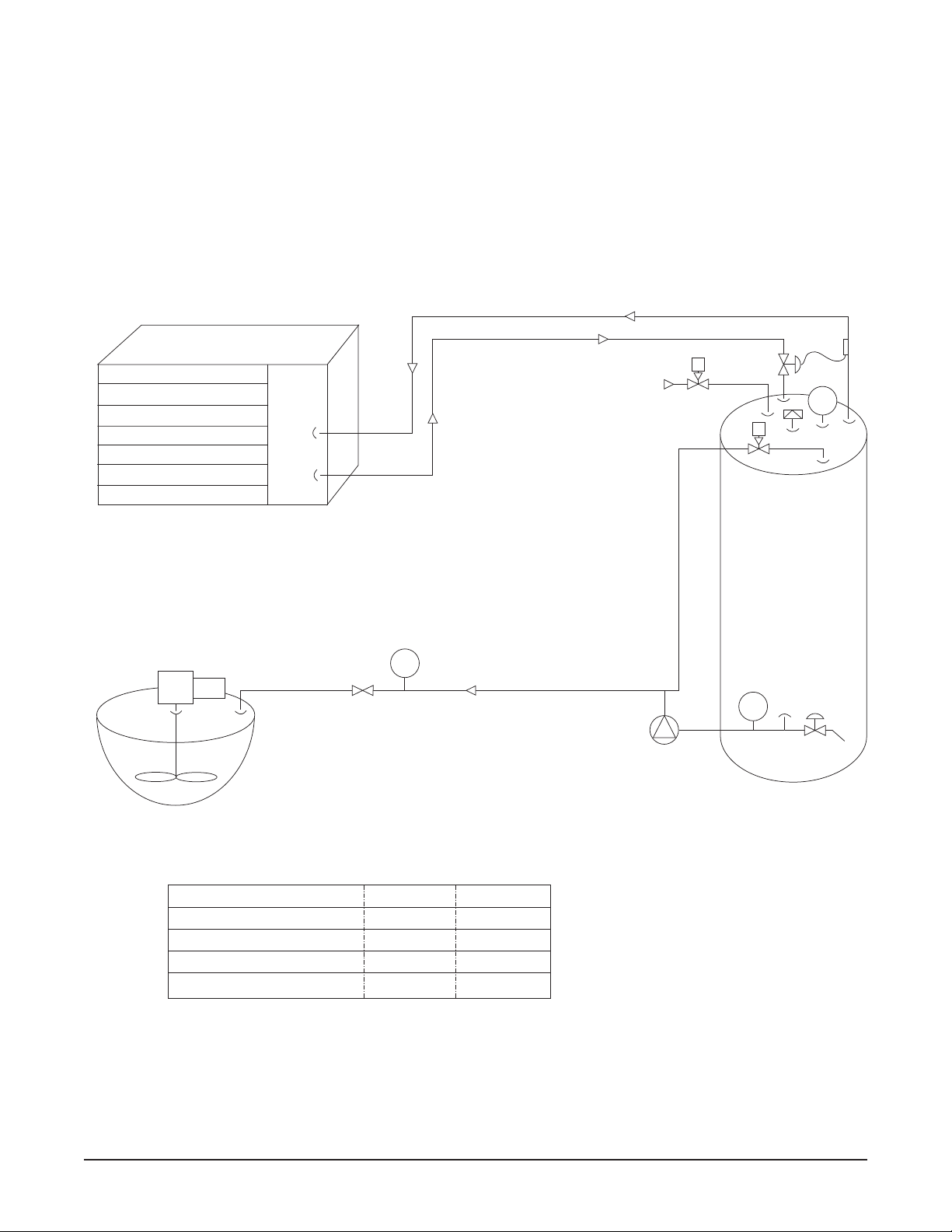
5.2 Bakery Chiller PMC Model 70/120 Flow Diagram
5.3 Bakery Chiller PMC Model 40/50 Flow Diagram
10
Inlet Water
Solenoid
Circulation Pump
Supply Water Inlet
Thermocouple
Drain
Valve
Water
Level
Switch
Chiller Barrel
Chilled
Water
Outlet
Process
Flow Switch
LS
1
TE
1
FS
1
S
Vent
S
Circulation Pump
Supply
Water
Inlet
Thermocouple
Drain
Valve
Water
Level
Switch
Chiller Barrel
Chilled
Water
Outlet
Process
Flow Switch
LS
1
TE
1
FS
1
Vent
S
Inlet Water
Solenoid
S
Page 14

Bakery Chiller Models PMC 40/50 and PMC 70/120 Effective February 23, 1999
Installation and Operation Instructions, Part No. 9842311 Revised May 7, 2009
SECTION 6.0 - PARTS ILLUSTRATIONS
6.1 Control Box
6.2 Control Box Parts List
11
ITEM NO.
NO. REQ’D. PART NO. DESCRIPTION
1 9842292 CONTROL BOX ASSEMBLY - BAKERY
1 1 9844261 CONTROLLER, TEMPERATURE
2 1 9842305 SWITCH, PUSH BUTTON, LIGHTED
3 1 8820718 TRANSFORMER, 208-240V, PRM, 24V SEC
4 1 9842306 SWITCH, RELAY, DPDT, 24VAC
5 2 9820091 FUSE BLOCK, 30 AMP, CLASS CC
6 1 505793 BARRIER, ELEC END FUSE
7 2 9823754 FUSE, CARTRIDGE, 7 AMP
8 2 8820703 FUSE, BLOCK, 30 AMP
9 1 8806523 FUSE, CARTRIDGE, 2 AMP
10 6 8805635 TERMINAL BLOCK
11 1 8805636 BARRIER, ELEC END
12 2 8805226 CLIP, RETAINER
13 2 8820240 RELAY, SWITCH, DPST, 24VAC
14 1 8820165 THERMOCOUPLE, SENSOR, TYPE “T”
15 1 30853 SWITCH, TOGGLE, DPST
®
8820261
PRODUCT
MODEL NUMBER PART NUMBER SERIAL NUMBER
VOLTS HERTZ PHASE LRG MTR AMPS FLA
DISCONNECT MAIN POWER SUPPLY BEFORE SERVICING.
ROMPRE LE CABLE DE DISTRIBUTION AVANT DE REPARER.
0007 30890
FRONT VIEW
BACK PANEL LAYOUT
Page 15

Bakery Chiller Models PMC 40/50 and PMC 70/120 Effective February 23, 1999
Installation and Operation Instructions, Part No. 9842311 Revised May 7, 2009
6.3 Chiller Assembly Model PMC 40/50
12
DETAIL C
DETAIL B
TOP VIEW
ELEVATION VIEW
DETAIL A
Page 16

Bakery Chiller Models PMC 40/50 and PMC 70/120 Effective February 23, 1999
Installation and Operation Instructions, Part No. 9842311 Revised May 7, 2009
6.4 Chiller Assembly Parts List Model PMC 40/50
13
ITEM NO.
NO. REQ’D. PART NO. DESCRIPTION
1 9842289 CHILLER, BAKERY MODEL PMC 40/50
1 1 9842259 WATER PUMP, CIRCULATING, .75HP
2 1 9842292 CONTROL BOX ASSEMBLY
3 1 9842309 SWITCH, FLOW, MAGNETIC
4 2 9842295 VALVE, SOLENOID, .75" NPT
5 1 9842300 VENT, TANK, .75" FPT
6 1 8802042 TUBE, INLET WATER
7 1 9843059 SWITCH, LEVEL
8 1 30041 CLAMP, HOSE
9 .007SF 3202023 RUBBER, .125" THK
10A 1 9842303 VALVE, EXPANSION, R-22
10B 1 9844289 VALVE, EXPANSION, R-507
11 3 93755 LEG, ASSEMBLY
12 1 9843187 REGULATOR FLOW .75", 10 GPM
Page 17

Bakery Chiller Models PMC 40/50 and PMC 70/120 Effective February 23, 1999
Installation and Operation Instructions, Part No. 9842311 Revised May 7, 2009
6.5 Chiller Assembly Model PMC 70/120
14
DETAIL A
DETAIL B
DETAIL E
TOP VIEW
DETAIL F
DETAIL D
ELEVATION VIEW
Page 18

Bakery Chiller Models PMC 40/50 and PMC 70/120 Effective February 23, 1999
Installation and Operation Instructions, Part No. 9842311 Revised May 7, 2009
6.6 Chiller Assembly Parts List Model PMC 70/120
15
ITEM NO.
NO. REQ’D. PART NO. DESCRIPTION
1 9842291 CHILLER, BAKERY MODEL PMC 70/120
1 1 9842259 PUMP, WATER, CIRCULATING, .75HP
2 1 9842292 CONTROL BOX ASSEMBLY
3 1 9842309 SWITCH, FLOW, MAGNETIC
4 2 9842295 VALVE, SOLENOID, .75" NPT
5 1 9842315 VENT, TANK, 1.25" FPT
6 1 8802042 TUBE, INLET WATER
7 1 9843059 SWITCH, LEVEL
8 1 30041 CLAMP, HOSE
9 .007SF 3202023 RUBBER, .125" THK
10A 1 8802355 VALVE, EXPANSION, R-22
10B 1 9844291 VALVE, EXPANSION, R-507
11 4 93755 LEG, ASSEMBLY
12 1 9842317 DISTRIBUTOR
13 1 9843187 REGULATOR FLOW .75", 10 GPM
Page 19

Bakery Chiller Models PMC 40/50 and PMC 70/120 Effective February 23, 1999
Installation and Operation Instructions, Part No. 9842311 Revised May 7, 2009
SECTION 7.0 - REFRIGERATION UNITS
7.1 Specifications/Electrical Data for PMC 40/50 With 2 HP Unit
7.2 Specification/Electrical Data for PMC 70/120 With 3.5 HP Unit
NOTE: The 2.0 hp remote condensing unit is suitable for outdoor operation with the addition of lowambient controls and weather protection. Call the factory for more information.
16
SPECIFICATIONS
Unit Overall Dimensions Liquid Suction Approximate
Part Model (inches) Line Line Shipping Weight Compressor
Number Number Length Width Height Valve Valve (lbs.) Model No.
9842322 F3AM-A201 24.1 18.3 16.9
3
/8FL7/8SWT 140 CRD1-0201
9844295 FJAM-A150 24.1 18.3 16.9
3
/8FL7/8SWT 140 CS10K6E
ELECTRICAL DATA
Unit 208-230/1/60
Model Elec. M/C Max
Number Code Amps Fuse
F3AM-A201 -CFV 19.7 30
FJAM-A150 -CFV 19.7 30
SPECIFICATIONS
Unit Overall Dimensions Liquid Suction Approximate
Part Model (inches) Line Line Shipping Weight Compressor
Number Number Length Width Height Valve Valve (lbs.) Model No.
8822363 OESE-A351 40.1 30.4 31.5
3
/8SWT7/8SWT 358 ZB26KA-PFV
8822362 OESE-A353 40.1 30.4 31.5
3
/8SWT7/8SWT 358 ZB26KA-TFS
ELECTRICAL DATA
Unit 208-230/1/60 208-230/3/60
Model M/C Max M/C Max
Number Amps Fuse Amps Fuse
OESE-A351 23.0 30
OESE-A353 16.5 20
Page 20

Bakery Chiller Models PMC 40/50 and PMC 70/120 Effective February 23, 1999
Installation and Operation Instructions, Part No. 9842311 Revised May 7, 2009
7.3 Refrigeration Cycle Diagram
7.4 EPA Refrigerant Regulations*
The Mueller bakery chiller system is designed to operate with R-22 (chlorodiflouromethane), a Class II
HCFC refrigerant. R-22 refrigerant is specified by ASHRAE Standard 34 Safety Classification as an “A-1”
refrigerant that represents low-flame propagation and low toxicity.
EPA regulations require that any technician performing refrigerant installation or service on a high
pressure appliance be certified as a Type II Technician in accordance with Section 608 of the Clean Air
Act.
*As adopted for the United States and Canada. These regulations may change or differ for your locality.
It is the responsibility of the technician performing the refrigerant service and/or installation to abide by
all regulatory requirements for the installation locality, state, and country.
7.5 Thermal Expansion Valve (TEV) Superheat Adjustment
Take the following readings with the water storage tank full of water at a temperature below 40°F.
1. Take an accurate suction pressure at the evaporator outlet.
SERVICE NOTE: The suction pressure must be taken at the evaporator outlet rather than the
suction-service valve due to unknown pressure drop in the refrigerant line between the evaporator
and compressor (refer to Figure 8). The technician should also make certain that the system is
charged with refrigerant as described in Section 2.0.
2. Utilizing an accurate electronic thermometer, take the actual suction line temperature near the TEV
sensing bulb.
17
Air-Cooled Condensing Unit
Suction Line
Service Valve
Liquid Line
Service Valve
Liquid Line
Suction Line
Liquid Line
Sight Glass
Thermostatic
Expansion
Valve
Bakery Chiller
Page 21

Bakery Chiller Models PMC 40/50 and PMC 70/120 Effective February 23, 1999
Installation and Operation Instructions, Part No. 9842311 Revised May 7, 2009
7.5 Thermal Expansion Valve (TEV) Superheat Adjustment (Continued)
3. Utilizing an R-22 or R-507 Pressure Temperature Chart, convert the suction pressure reading from
Step 1 to saturation temperature.
4. The superheat value is found by subtracting the saturation temperature determined in Step 3 from
the actual suction line temperature taken in Step 2.
5. If the superheat is not in the range of 8 to 10°F, at conditions as described above, adjust the TEV.
6. If the superheat is below 8°F, turn the TEV’S adjustment stem clockwise 1/8to 1/4of a turn. Allow
the system to operate for 5 minutes before repeating test.
7. If the superheat is above 10°F, turn the TEV’s adjustment stem counterclockwise 1/8to 1/4of a turn.
Allow the system to operate for 5 minutes before repeating test.
8. Any time adjustment is made to the TEV, the refrigerant charge should be checked.
9. Check the superheat setting and make final adjustments at a product temperature near setpoint for
best performance.
7.6 Thermal Expansion Valve Superheat Adjustment Diagram
18
Air-Cooled Condensing Unit
Suction Line
Service Valve
Liquid Line
Service Valve
Suction Line
Liquid Line
Thermostatic
Expansion
Liquid Line
Sight Glass
Valve
TEV
Sensing Bulb
Bakery Chiller
Thermometer
Suction Gauge
Page 22

Bakery Chiller Models PMC 40/50 and PMC 70/120 Effective February 23, 1999
Installation and Operation Instructions, Part No. 9842311 Revised May 7, 2009
SECTION 8.0 - WARRANTY
WARRANTY
Mueller®Bakery Chiller
One Year Parts Warranty
The Paul Mueller Company (hereafter referred to as Company) will repair or (at the Company’s option) replace
any part or portion of a Mueller Bakery Chiller found to be defective in workmanship or material under normal
use, service, and installation procedures, for a period of one (1) year from the date of installation by the
original purchaser-user, or eighteen (18) months from the date of shipment from the Company factory,
whichever occurs first. This warranty covers replacement of parts or repair of the equipment only. (See General
Provisions).
Claim Procedures for One Year Parts Warranty
All defective parts covered by the one year parts warranty, must be returned to the Company with an attached
Returned Goods Tag (Form O-209) and with transportation cost prepaid. Current instructions provided by the
Refrigeration Products Department for return procedures must be followed to receive warranty.
Five-Year Structural Warranty
The Company warrants to the original purchaser-user that the Mueller Bakery Chiller evaporator (cooling plate)
and water storage tank will remain free from defects in material and workmanship under normal use, service,
and installation procedures for a period of five (5) years from the date if installed by the original purchaser-user
or sixty-six (66) months from date of shipment from the Company factory, whichever comes first. Under this
warranty, the Company’s obligation shall be limited to the repair or, at the Company’s option, the replacement
of the Bakery Chiller evaporator or water tank. Damage caused by freezing is not covered by this warranty.
(See General Provisions).
Claim Procedures for the Five-Year Warranty
A return authorization number must be obtained from the Paul Mueller Company’s Refrigeration Products
Department prior to returning a Mueller Bakery Chiller evaporator or water tank. Current instructions, provided
by the Refrigeration Products Department for return procedures, must be followed to receive warranty.
General Provisions
Transportation and inspection cost incurred by the Company will be charged to the purchaser/user if returned
material is not found to be defective. This warranty does not cover items such as refrigerant, mileage, product
loss, cost of substitute storage facilities, parts and labor charged by others, or consumable items such as filter
driers, rubber goods, or glass. The above will constitute the Company’s total responsibility. The above
Warranties will not apply in the event of abuse, misuse, negligence, improper installation procedures alterations
by unauthorized service, damage by flood, fire, windstorm, lightning or acts of God. Oral statements made by
employees’ or representatives’ of the Company will not constitute warranties. The above Warranties apply only
to the original purchaser-user and original installation location and are not transferable.
This warranty is effective on Mueller Bakery Chillers purchased within the continental United States
and Canada. Contact the Mueller International Sales Department for warranty provisions and policies
outside of the continental United States and Canada.
Paul Mueller Company
P.O. Box 828 • Springfield, Missouri 65801-0828, U.S.A.
Phone: (417) 575-9000 • Fax: 1-800-436-2466
19
®
Page 23

Bakery Chiller Models PMC 40/50 and PMC 70/120 Effective February 23, 1999
Installation and Operation Instructions, Part No. 9842311 Revised May 7, 2009
SECTION 9.0 - INSTALLATION AND SERVICE NOTES
Customer Name: Dealer Name:
Address: Address:
Telephone: Telephone:
Quad Plate Chiller Model: Serial No.:
Compressor Model: Serial No.:
Date of Installation:
Notes:
20
Page 24

P.O. Box 828 • Springfield, Missouri 65801-0828, U.S.A.
Phone: (417) 575-9000 • 1-800-MUELLER • Fax: 1-800-436-2466
www.muel.com • E-mail: refrigeration@muel.com
©1999-2009 Paul Mueller Company (5/09) 9842311
®
 Loading...