

Page 1
Instruction manual
BKM 55-75-100
Page 2

Table of contents
Table of contents...............................................................Fout! Bladwijzer niet gedefinieerd.2
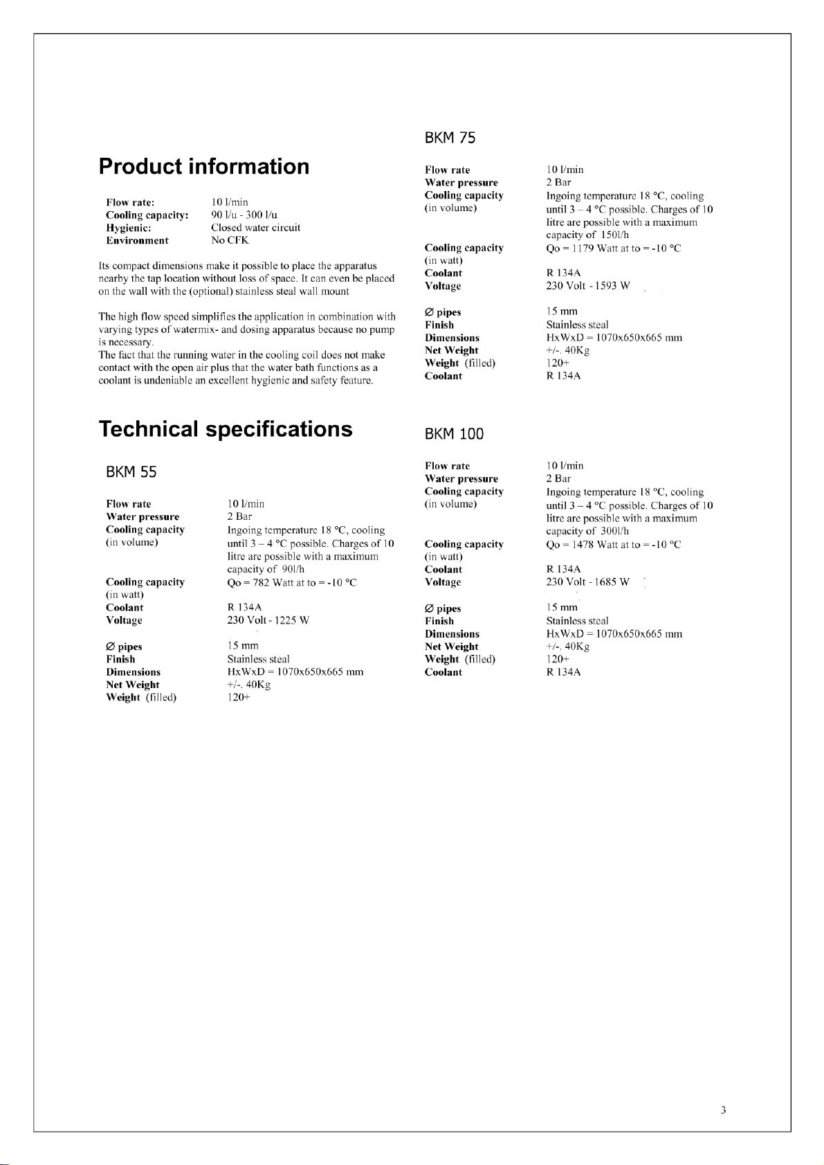
Productinformation.................................................................................................................. 3
Technical specifications ...........................................................................................................3
Makombi BKM 55................................................................................................................................. 3
Makombi BKM 75................................................................................................................................. 3
Makombi BKM 100............................................................................................................................... 3
Installation ................................................................................................................................4
maintenance........................................................................Fout! Bladwijzer niet gedefinieerd.
Elektrical sketch.................................................................Fout! Bladwijzer niet gedefinieerd.
Parts list..................................................................................................................................... 5
Temperature display................................................................................................................6
Electrical sketch conversion module (110 volt units only)....................................................7
2
Page 3
Page 4

Installation
• The chiller must be installed so that the suction and discharge of air can take
place properly. Keep free space surrounding the chiller at least 10 cm
• Connect the ingoing water pipe
• Connect the outgoing water pipe
• Fill up the water tank with fresh water ( ± 125 l )
• Plug the chiller in a earth connected wall connection
• Switch the chiller on by turning the thermostat knob clockwise
The electrical installation must be saved with a 16amp. fuse
…………………………………………………………………… Nr. 6 page 5
……………………..……………………………………………. Nr. 8 page 5
……………………………………………. Nr. 7 page 5
………………………………………… Nr. 9 page 5
Maintenance
• The water in the water tank must be refreshed once a year minimum
• Check the water level in the water tank on a regular basis and fill up if necessary
• The condenser must be cleaned regularly with a soft brush to remove dust for a proper airflow
Electrical diagram
Koelwaterthermostaat
Startrelais
Compressor koelventilator roerwerk
4
Page 5

Parts list
1 Thermostat
2 Cooling coil
3 Water coil
4 Flow control (10 l/min)
5 Temperature sensor (pt 100)
6 Ingoing water connection with tap
and flow back safety
7 Overflow
8 Outgoing water connection
9 Power connection (230 or 110 V)
11 Stainless steal casing
12 Lid
13 Waterfan motor connection (230 V)
14 Waterfan motor (230 V)
15 Condenser
16 Type plate with:
• Serial number
• Manufacturer
• Type
• Compressor type
• Power (Volt & Amp.)
• Year
• Coolant type and amount
• Max. pressure
• Test pressure
5
Page 6

Temperature display
Display
At the power up the unit shows “---” during 3 seconds approximately during which it performs a self check, then the current value
according to the configuration set appears. If the SIM is different from 0 it’s possible to display the instantaneous value by pressing
+ . The unit permanently stores the minimum and maximum values measured during the normal operation. The stored values are
displayed by respectively pressing button
If the readout exceeds the limits then “OR” is displayed, while in case of probe failure “PF” appears.
Configuration (setup)
Access to the configuration of the unit takes place through the following sequence: switch of the unit (unplug the power cord of the chiller),
keep buttons
get its value displayed with
10 seconds.
Param. Value default
SCL Readout scale
ACC Resolution 01=1, 02=0.l, 3=max resolution 03
TYP Type of sensor 0, 1 00
LOR Minimum range -199..999 -50
HOR Maximum range -199..999 150
SIM Display induction slowdown 0..100 00
LAD Zero calibration -- -1.0
HAD span calibration -- -1.0
+ pressed then switch on unit again. Scroll through the parameter list with or until you get the desired one, then
and change it with + or + . Exit from the setup takes place by letting the keypad untouched for
or and cleared by pressing button for 1 second.
01 =°C 02 = °F
01
Wiring diagram
6
Page 7

Electrical diagram for agitator motor and temperature display (conversion from 110Volt to
220 Volt) Only on 110 volt units
7
 Loading...